

tlevine
-
Posts
1,944 -
Joined
-
Last visited
Content Type
Profiles
Forums
Gallery
Events
Posts posted by tlevine
-
-
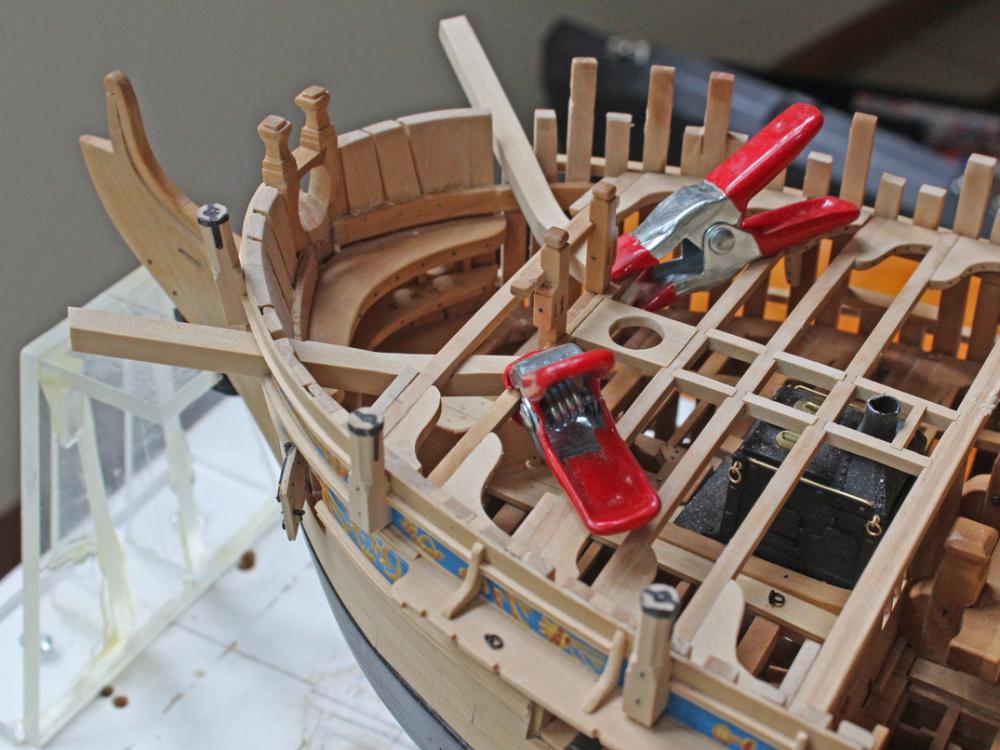
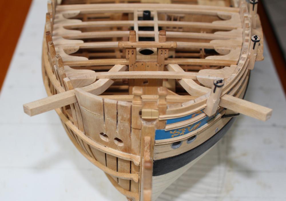
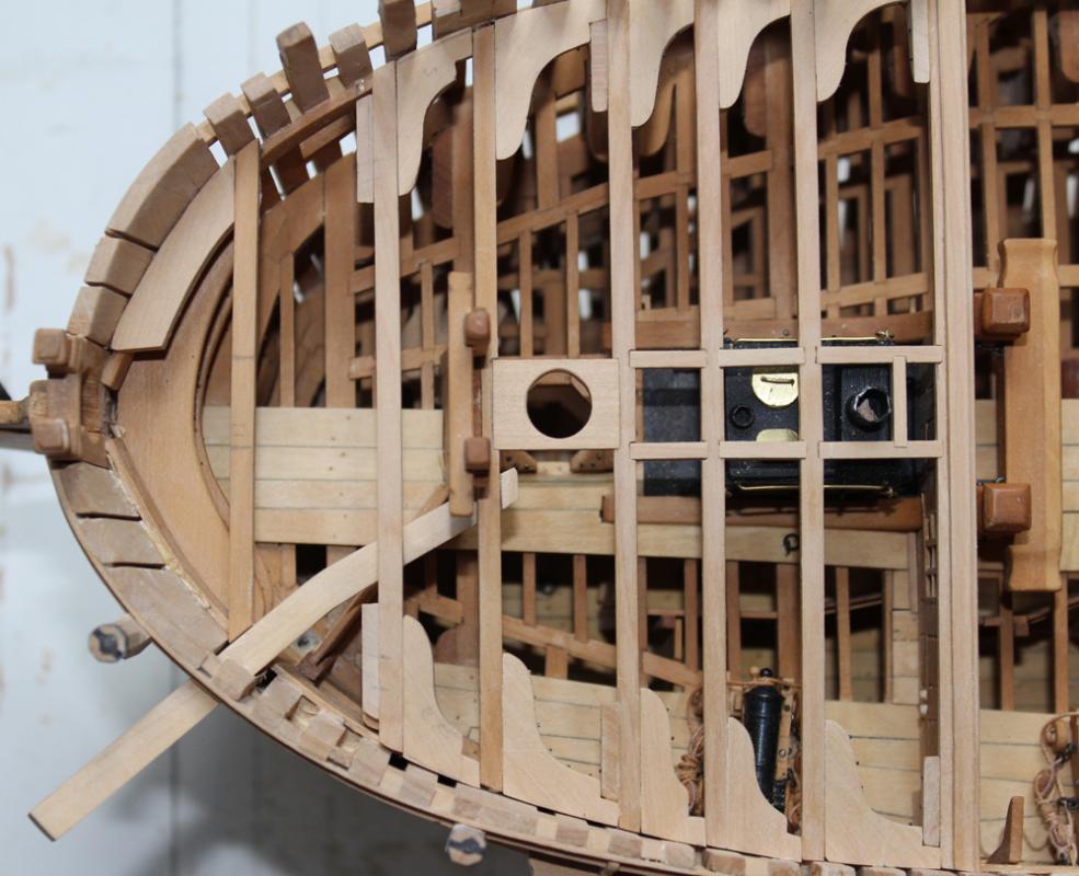
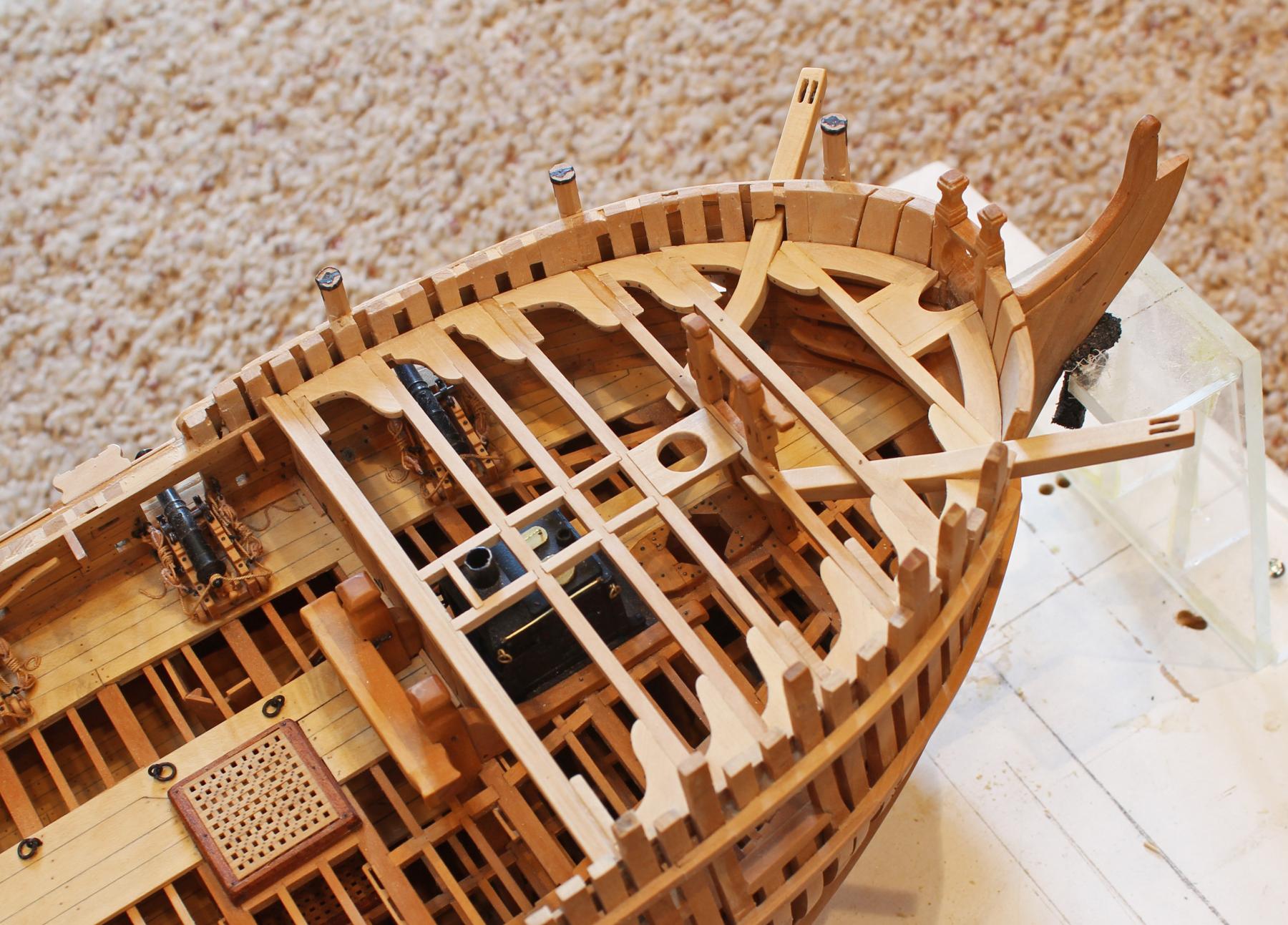
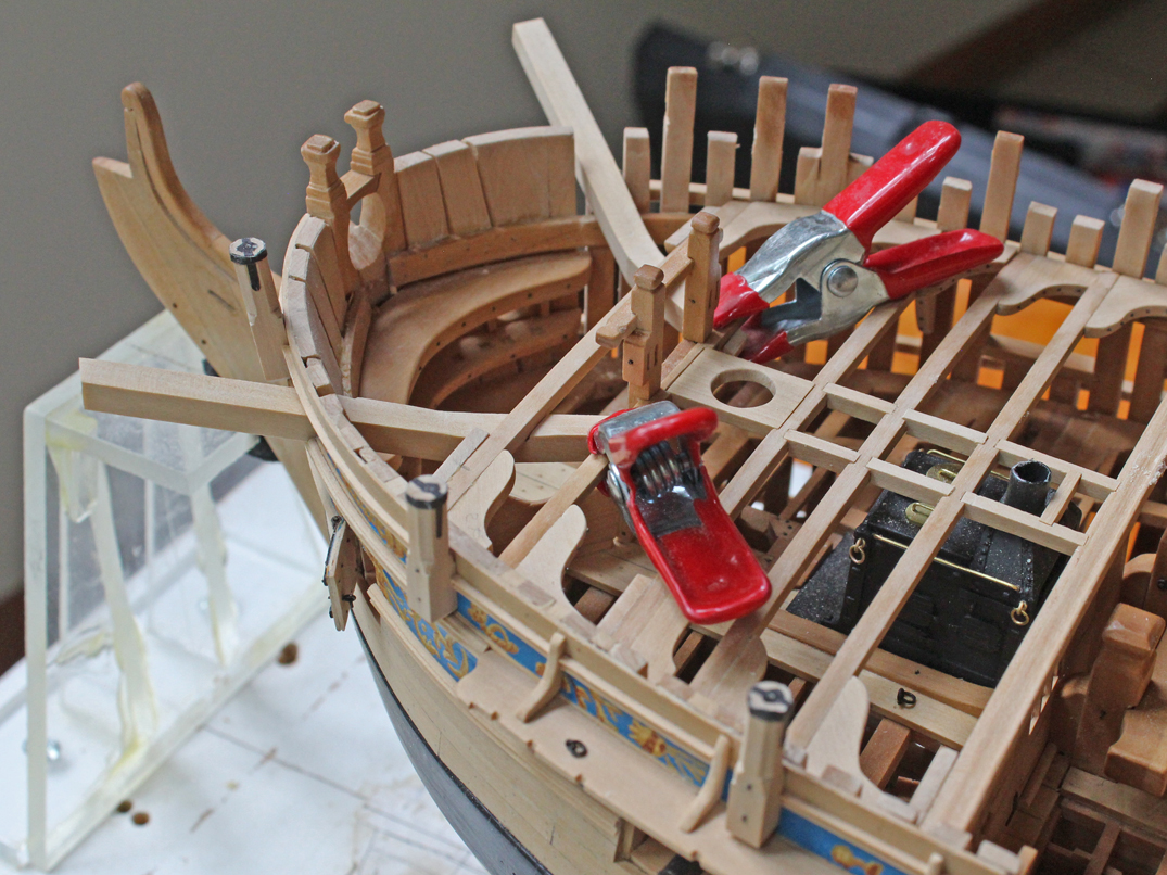
Work progresses on the forecastle framing and installing the catheads. There are two 9" sheaves in the cathead. These were made by drilling a series of holes along the length of the sheave opening perpendicular to the water line and then connecting the holes with an 11 blade. The sheaves were made from round brass stock, cut off on the Preac saw. These were then drilled for a pin. The cathead was also drilled and after blackening the sheaves and pin was inserted.
The cathead was inserted under the third beam and glued into place. Then the second beam with its associated knees were installed. Bolts were inserted through the two beams into the cathead. The first beam was then installed. Finally, the knee between the first and second beams was installed. This was initially fabricated as one piece. With the cathead in place, the middle portion of the knee was removed for a snug fit. Carlings were inserted between the deck clamp and the first beam to support the bowsprit partner. Mortises were made for the half hook laterally and the partner medially. Finally, the half hoods and partner were installed.
I have been practicing carving the cap for the cathead. Let us just say that it is a work in progress...


-
The gun carriage details are fantastic.
- WackoWolf, MarisStella.hr and mtaylor
-
 3
3
-
-
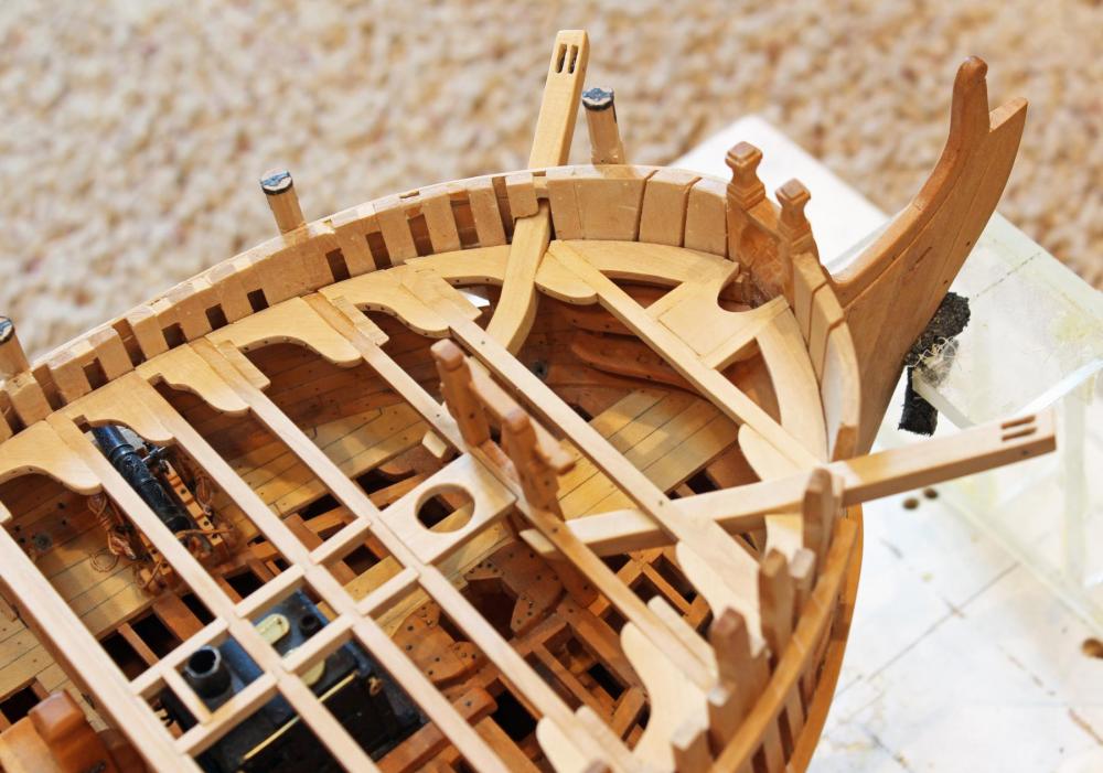
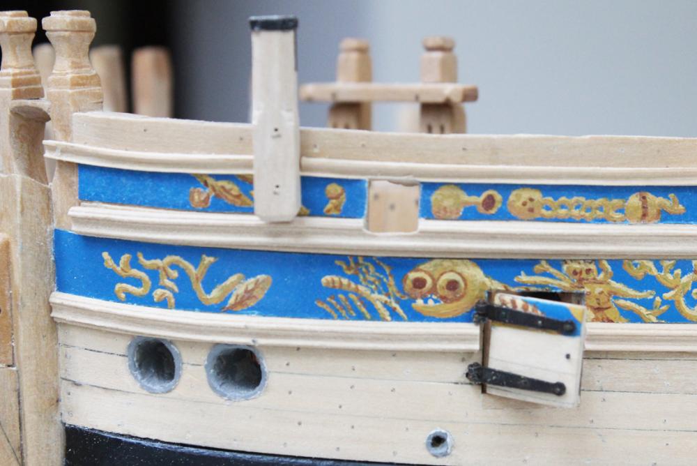
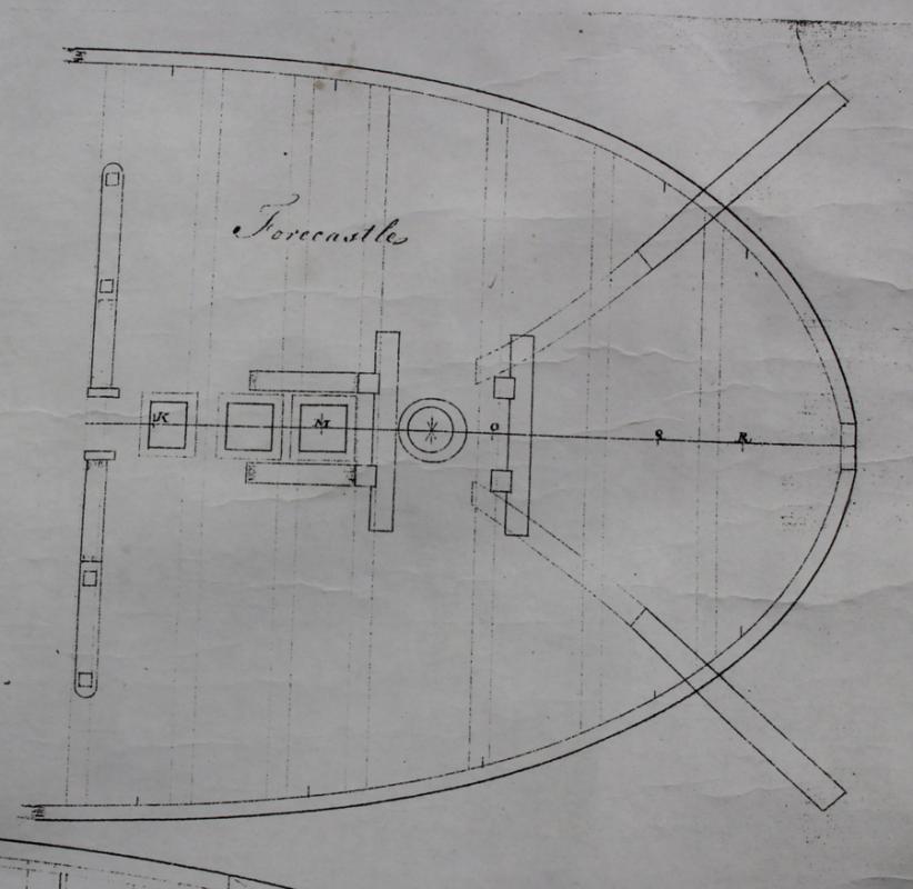
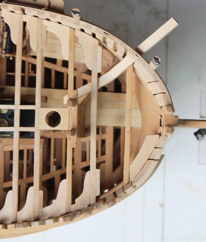
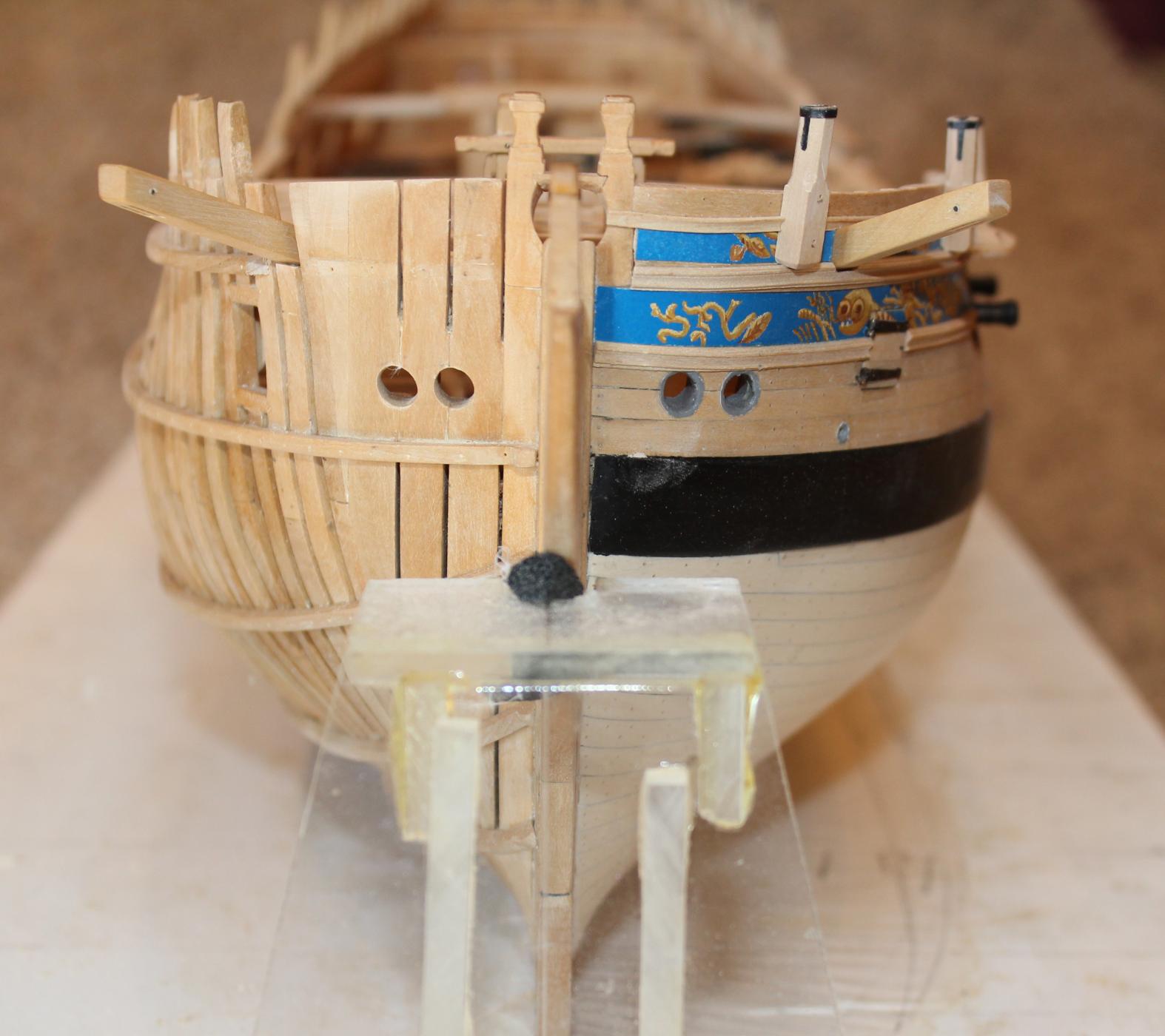
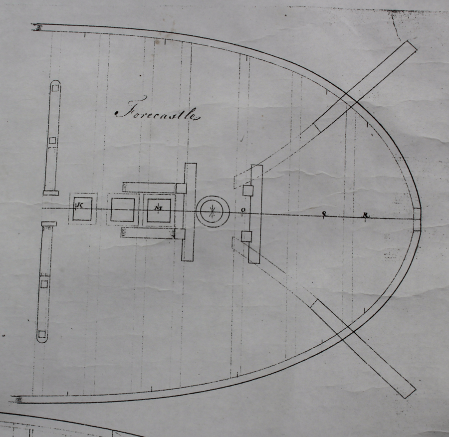
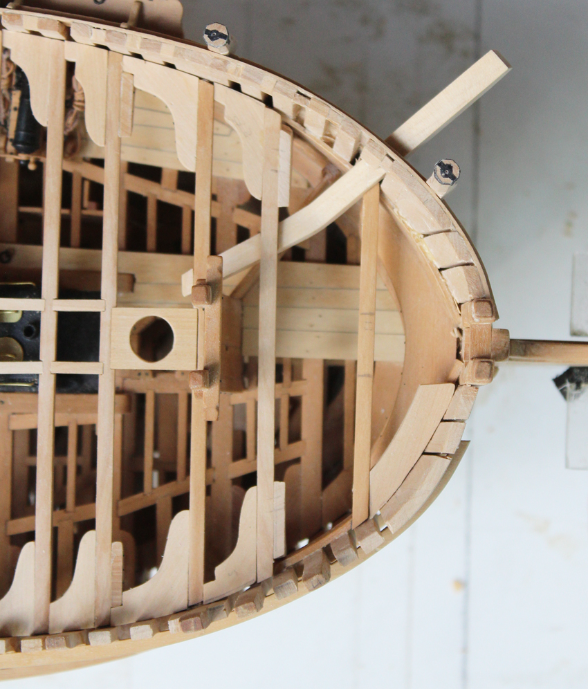
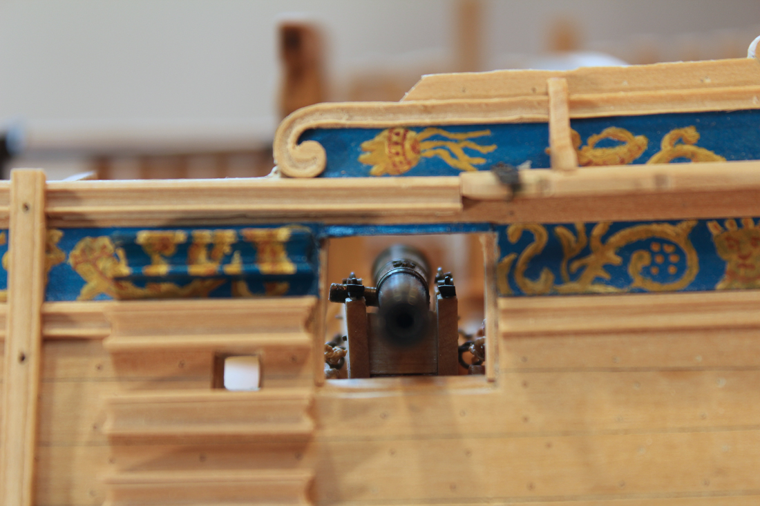
Now comes a scary part, cutting a hole into the hull. Mark the location for the hole based on the plan. Since the port side is fully planked I had to cut out a segment of the frieze and some of the molding. On the starboard side I removed a piece of ribband and one frame top. Once the cathead is installed, I will replace that frame top and secure it with filler pieces on either side. The cathead is inserted at an angle so the opening is directed downwards.
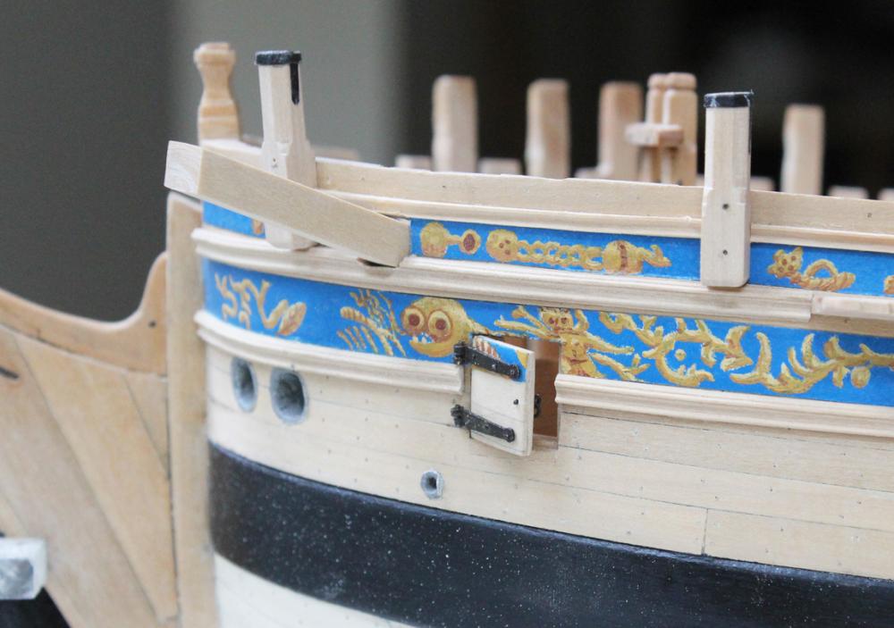
Referring back to the plan, note the angle that the cathead takes, insert it into the hole in the hull and place it under the third beam. Mark the beam location on the cathead and cut out the mortise in the cathead. Replace the cathead and temporarily place the second beam assembly on the deck clamp. Mark this beam location on the cathead and cut the mortise for this beam as well.

On my ship, possibly because of my previous measurement errors, the cathead crosses very close to the deck clamp. As a result I needed to notch both the first beam and the under surface of the cathead to get it into place. The unexpected benefit of this is that it locks everything securely into place. With the cathead secured, the outboard face was sanded to make it perpendicular to the water line. All the exposed edges were chamfered and the aft end was smoothed over, following the angle of the third beam. Still to go are the holes for the sheaves, the sheaves themselves and the decorative cap.


-
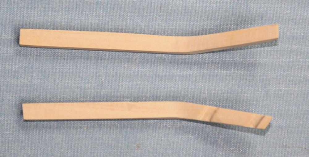
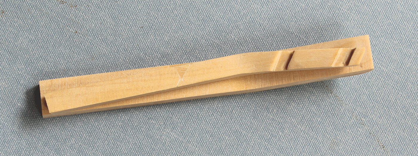
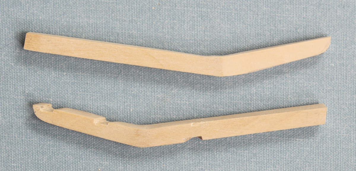
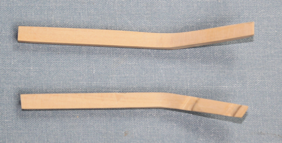
I will try and demonstrate how I made the cathead. Sorry for the picture quality but I was more interested in showing the technique than in cleaning up the model after each step.
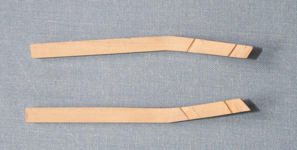
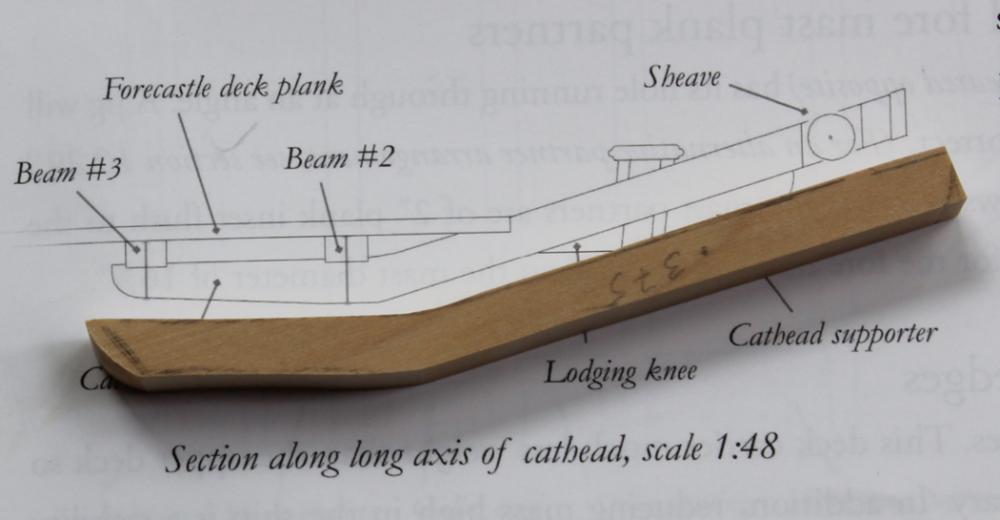
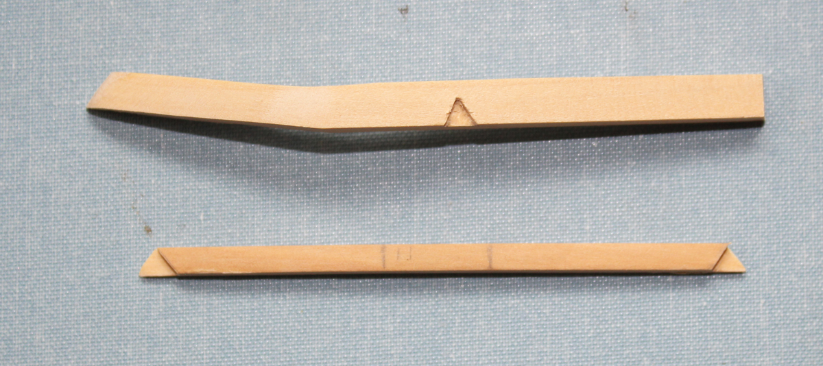
I went to the plan to determine the length and lateral bend of the cathead. TFFM has an excellent drawing of the upward angle. Because of the size of wood available to me I decided to transfer the drawing from TFFM onto a piece of 0.375 wood and cut this out on the scroll saw. I cut this overlong for final sizing later.
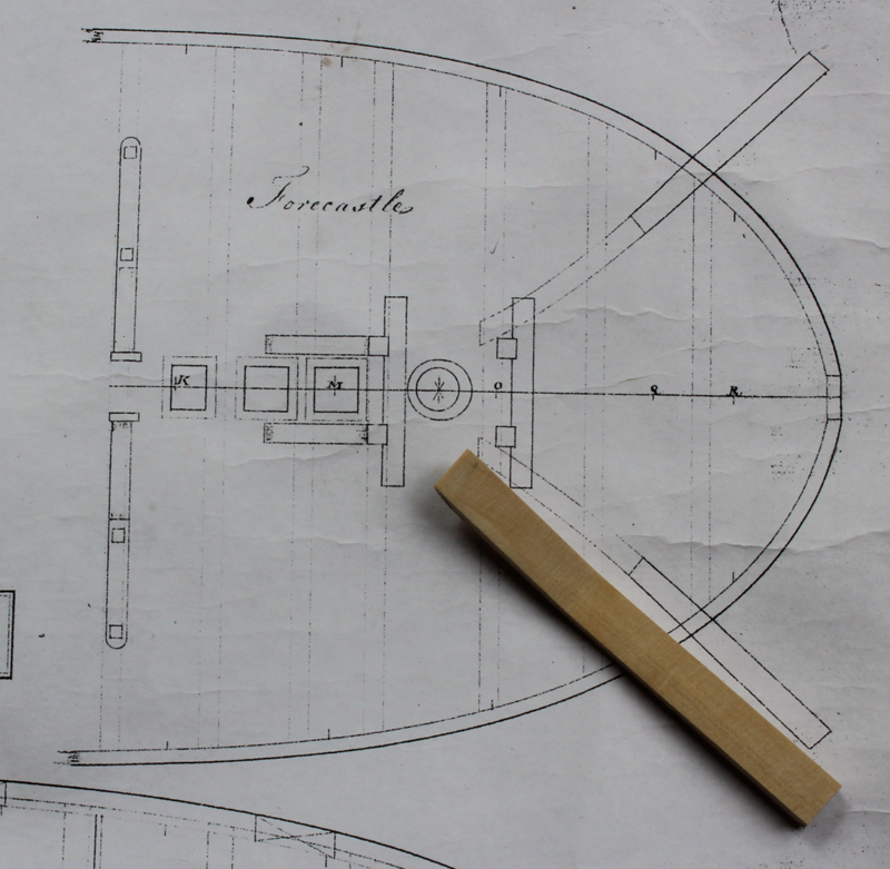
After that was done, I drew the lateral bend from the plan onto the blank. Please remember, these are mirror images of each other. As you can see, the port is cathead is already notched for the beams. My goal was to make them as similar to each other as possible.


-
-
-
Work has started on the cat head. This one piece has taken me over three hours to plan and fabricate. I still have to install the sheaves and finish sand it. I will show a few pictures today and will describe the steps of construction as I make the starboard one.
-
-
-
-
-
-
There has been a little progress over the last few weeks. Unfortunately, most of it has been backwards, not forwards.
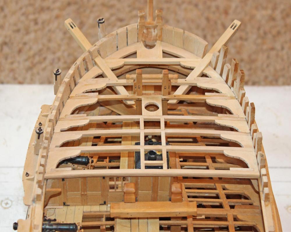
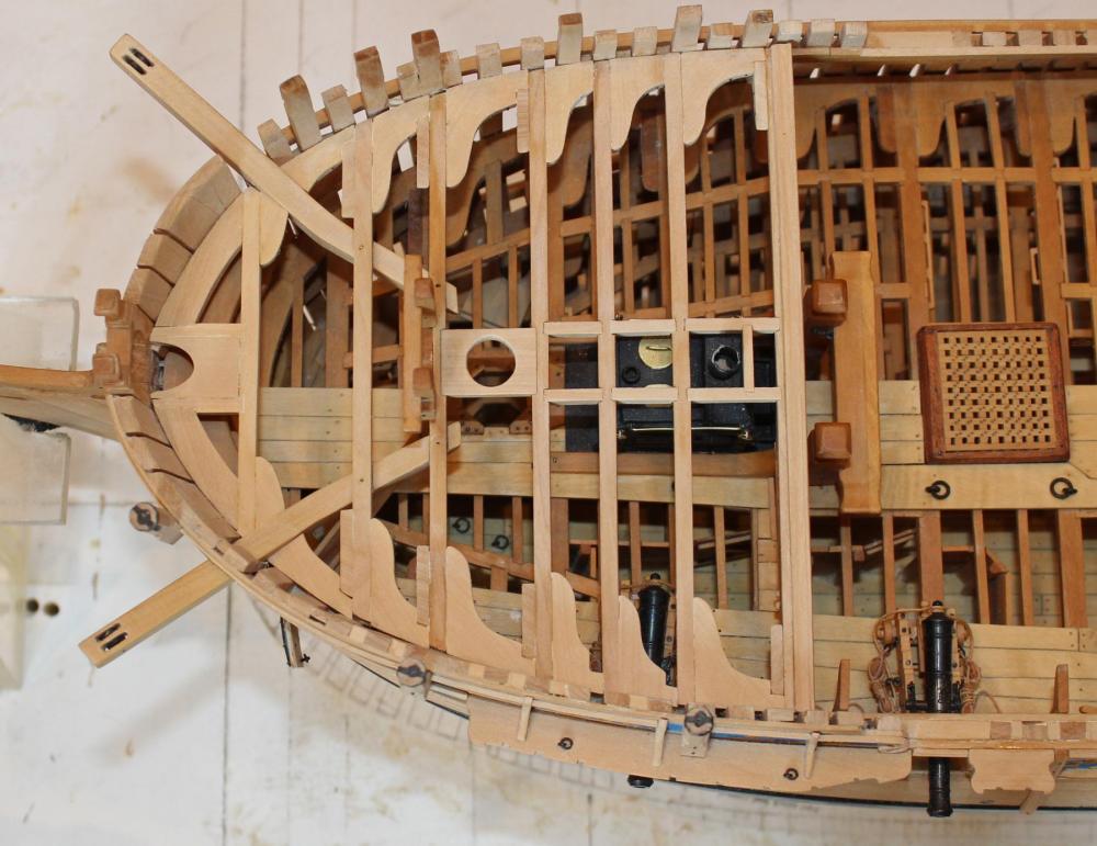
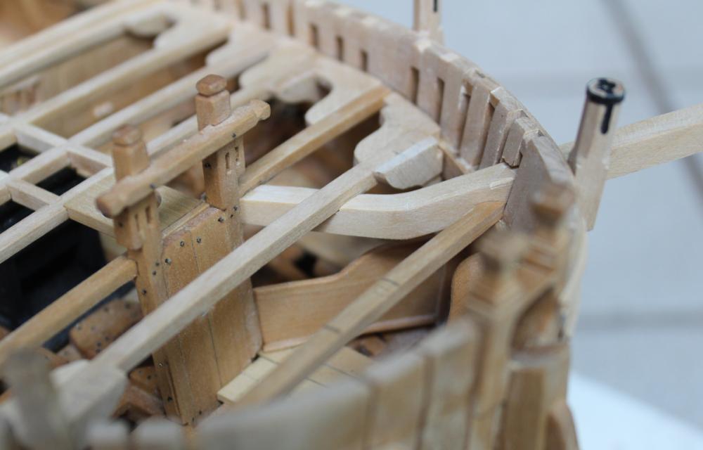
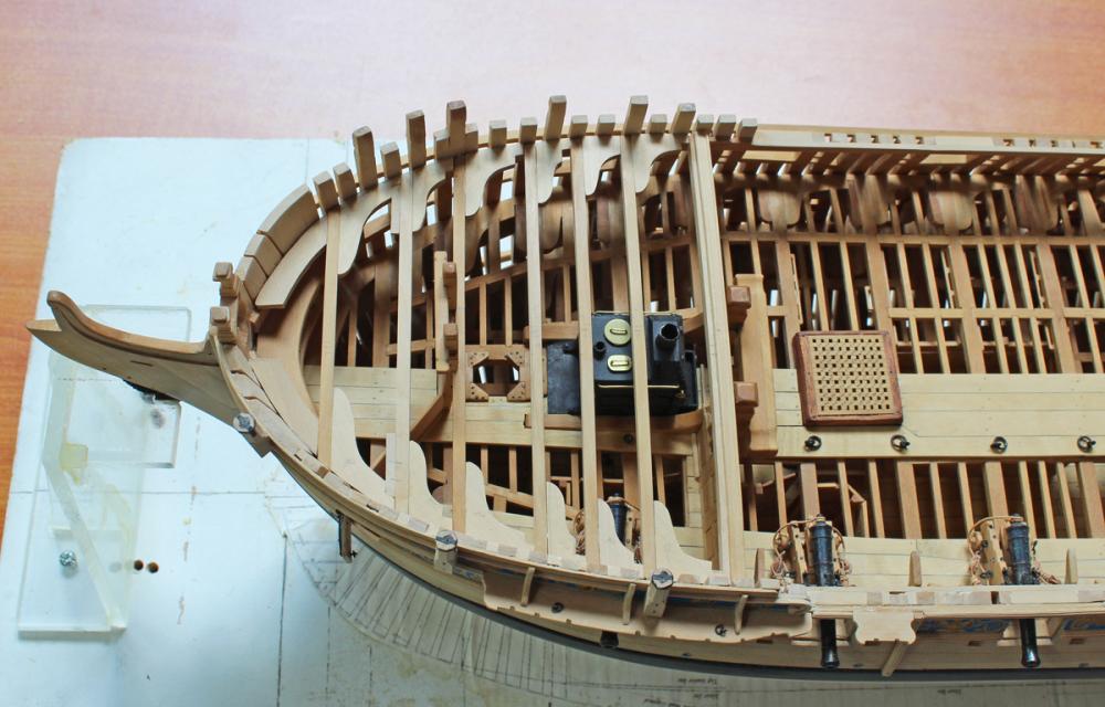
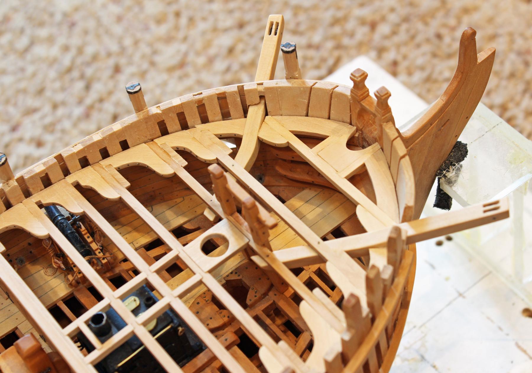
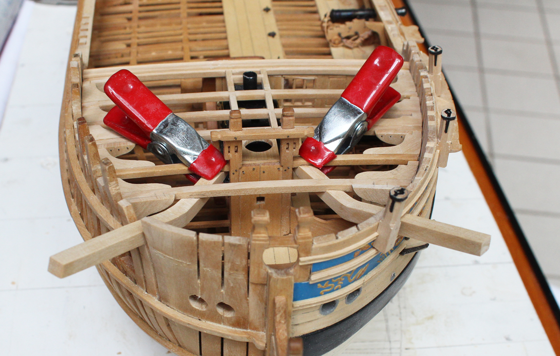
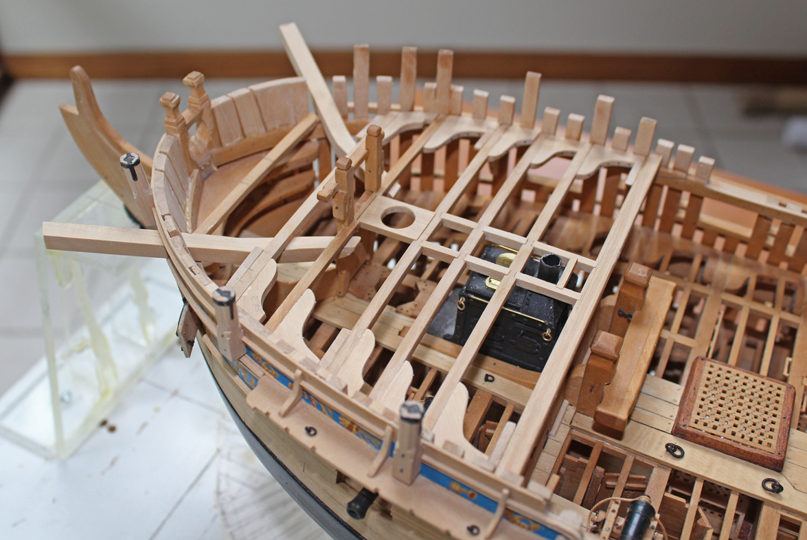
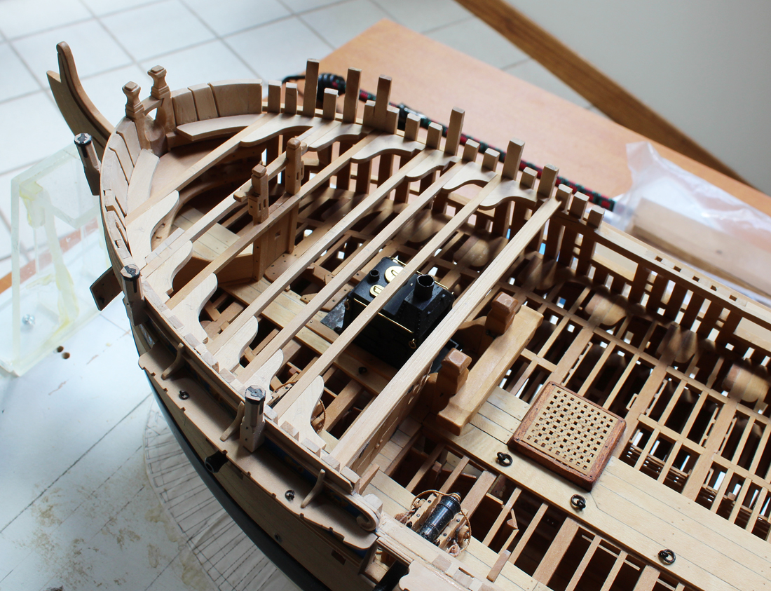
It is time to make the lodging and hanging knees for the forecastle. There are no pillars for these beams. The knees are made of 4.5" stock. They are fairly straightforward to make except that there is no hanging knee associated with the beam over the gun port (between beams 5 and 6). Needless to say, I goofed and cut the lodging knees for the hanging knee insertion. I replaced the starboard knee but left the port one since it will be planked over. Next, I started taking some measurements...and then some more measurements...and then some more measurements. I have become one of the many victims of cumulative error. The photocopied plan which was glued to the building board when this project was started is positioned 9" too far forward, so although all my measurements taken from the dead flat are correct, everything taken from the fore and aft extreme lines is off by 9". Additionally, the location of the cap rails is 4" too high.
None of this is truly a big deal from a construction of the hull perspective, although it will be a slightly different ship than constructed in 1775. The problem is that the bowsprit sits at a shallower angle and would cut through the foremost beam. Happily, I was not planning on masting her anyway. After this discovery and the frustration associated it there was only one thing to do. Walk away, have a cold one and come back the next day. Hopefully there will not be any more surprises down the road.
I moved the first two beams from the proposed layout in TFFM to prevent a hanging knee from interfering with the fore port opening. All the lodging knees and the first set of hanging knees are in place and tack-glued. The most difficult hanging knee is the one on the fore side of beam 2. The cant is this area is significant so there was a lot of trial and error fitting this in place.
The cattail still needs to be made and this cuts through one of the lodging knees and articulates with one of the beams so nothing will be secured until this is installed.

-
-
Didn't hurt at all, Druxey. The embarrassing thing is that it took someone else to point it out to me. That is the beauty of MSW. We are a community that really cares for the quality of work presented.
- Mirabell61, Martin W, Elijah and 7 others
-
10
-
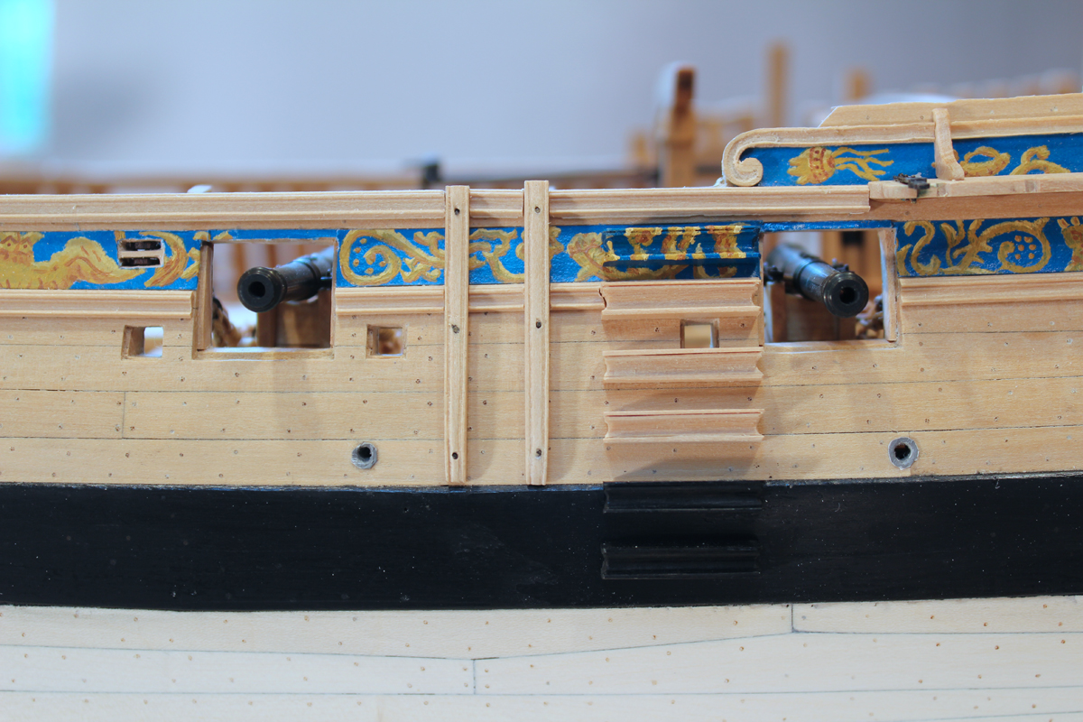
And here is the re-worked scroll.

-
Thank you for pointing the discrepancy out Mr. Rotten. Oh well, back to the carving board!
- mtaylor, Brian Oates, gjdale and 3 others
-
6
-
-
Thank you Albert and Druxey. And also thanks for all the likes.
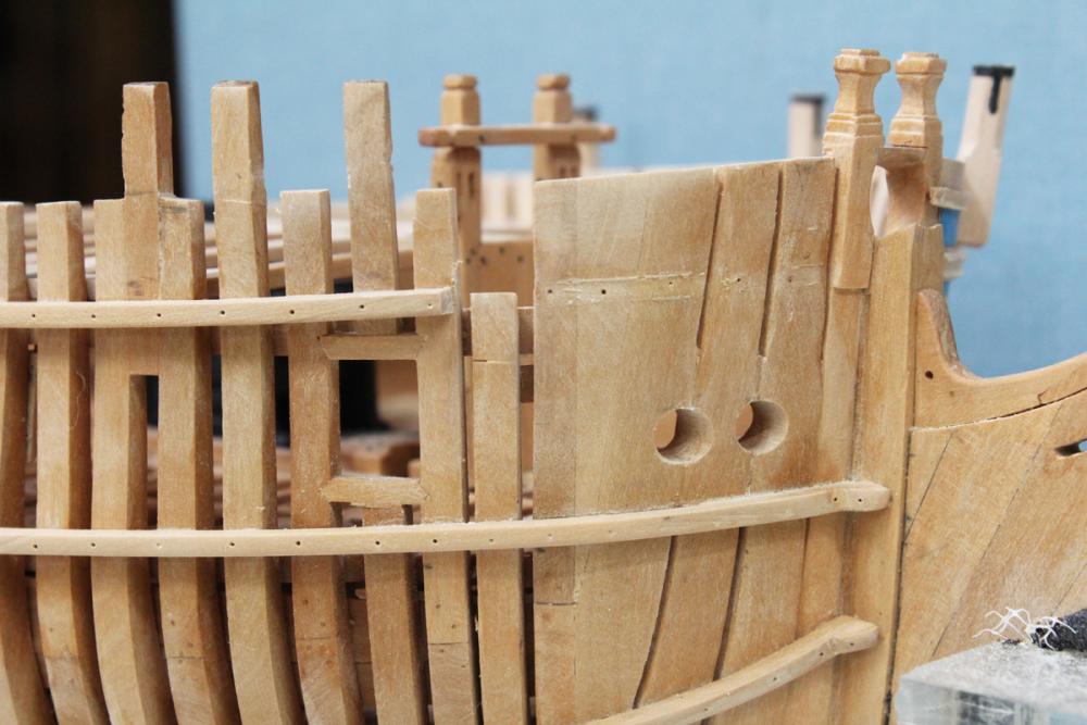
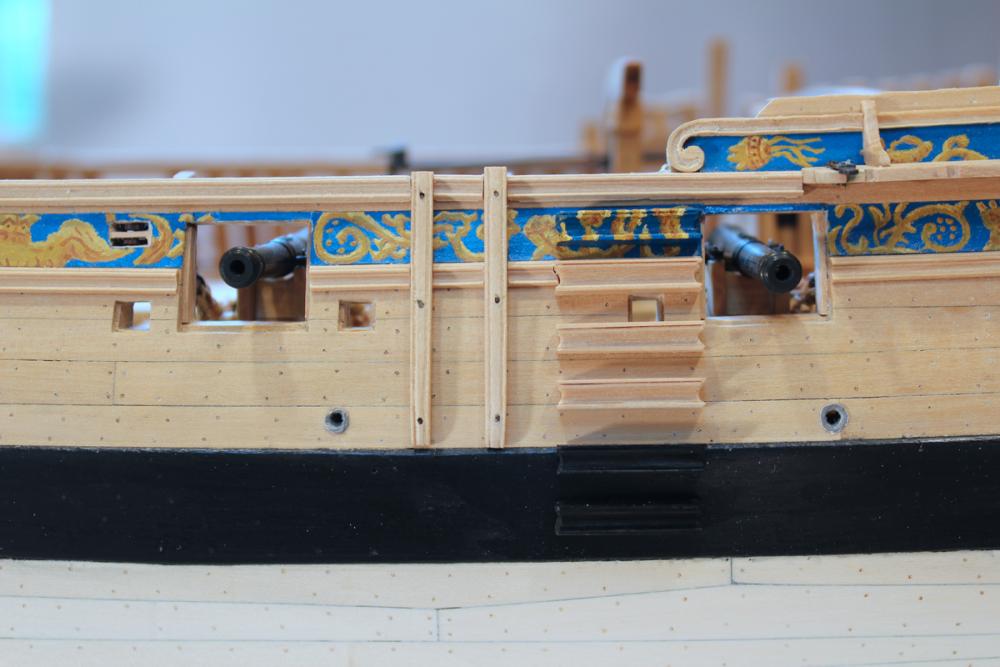
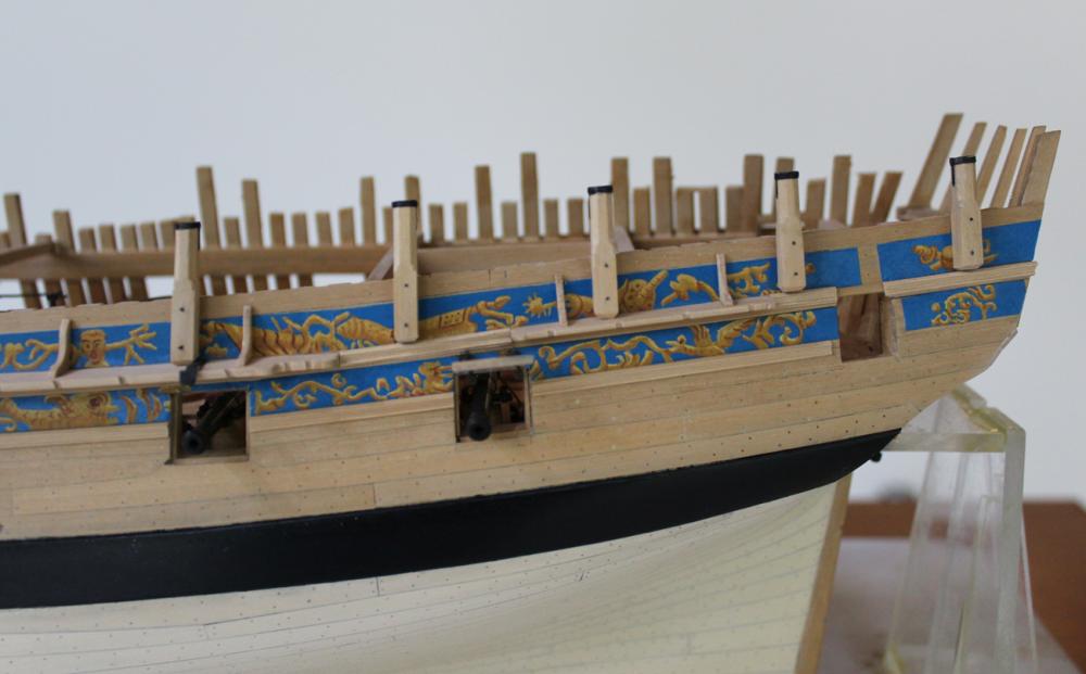
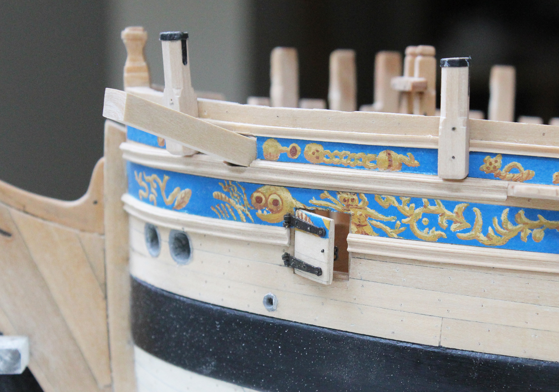
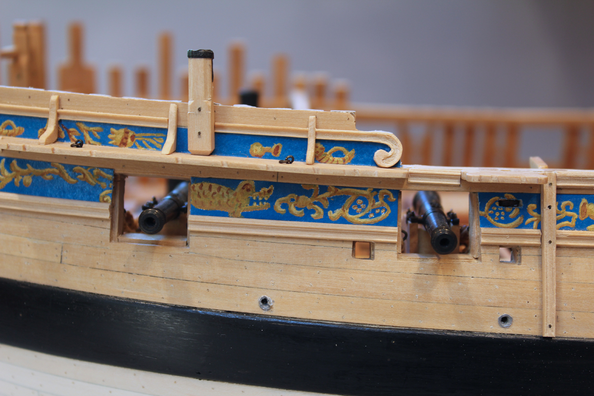
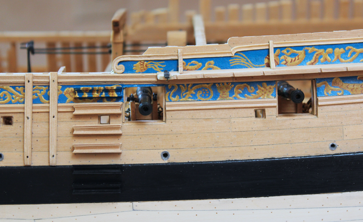
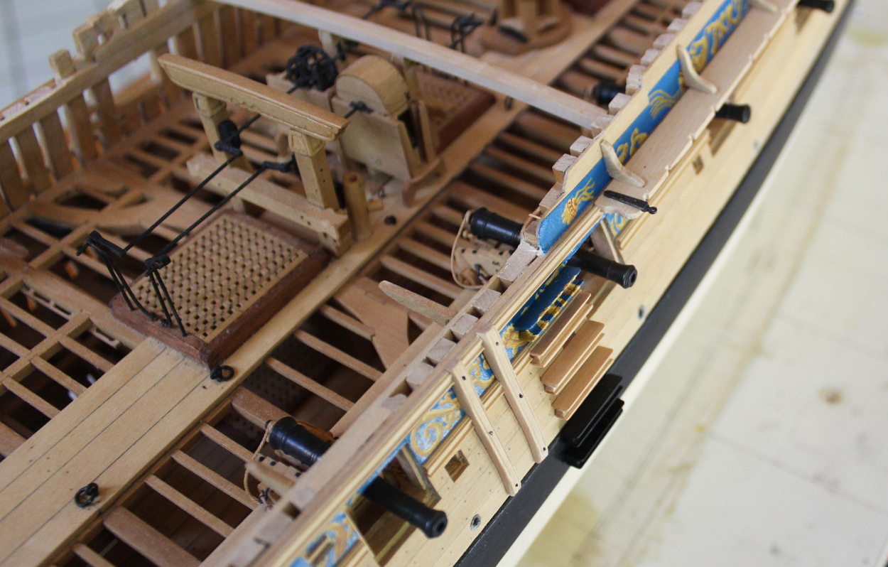
The next thing to attack was the drift rail and their scrolls. This is the topmost decorative rail and runs on the top edge of the frieze. It is interrupted by the channel brackets and swivel gun mounts. It is made in the usual fashion with the pattern carved into a razor blade. Now it gets interesting. The rail drops down between the fifth and sixth gunports. A rounded corner was needed to accommodate this drop. There is nothing terribly difficult about this or the scrolls. It is time consuming and fiddly but not hard to accomplish. I traced the shape on a wood blank and scraped the straight section with the razor. Then I carved the corner piece with tiny chisels and needle files. I would suggest to anyone doing this to make the vertical limb over-long at this point as it is prone to tear-out. One the shape was correct I fit it to the lower section of rail already in place with a 45 degree miter.
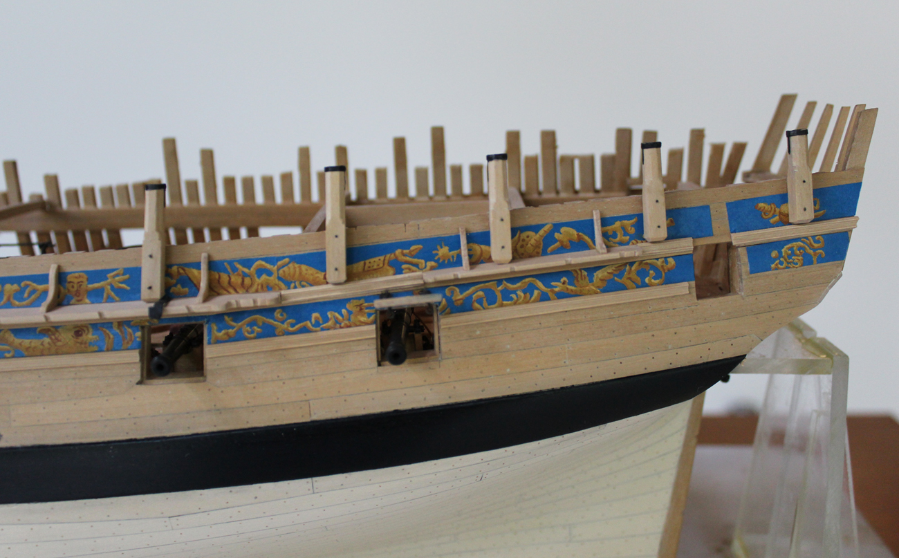
The scrolls were approached similarly. The shape was traced out on a blank and roughly shaped with chisels and an eleven blade. This blank was glued onto the back of a piece of sandpaper. The sandpaper helped prevent slippage on my cutting board during the shaping process. The straight section was scraped and the scroll was cut in. The thickness of the scroll diminishes as it drops down and increases again at the "ball". For the aft scroll this means that from 11:00 to 6:00 the thickness tapers in and from 6:00 to 3:00 it tapers out to the original thickness. Sorry about the picture quality. They actually look better than the pictures suggest.

-
Group projects for entire ships or boats are problematic for all the reasons presented here. Having said that, I built the longboat because it was a group build and put my other projects on hold during the building process. I would not have done that if the anticipated build time was months or years, rather than weeks. I like the idea of a group build of a specific part of a ship, whether this is a sail, capstan, wheel or stove. I definitely would participate in a group for carving.
-
Not too much has gotten accomplished on Atalanta these last few weeks. Two weeks ago she took a trip to the Midwest Model Ship Show in Manitowoc Wisconsin. Bill Maxwell's magnificent Fly and Atalanta were displayed next to each other as works in progress. Last week was spent in the garden. This week it rained so much I was able to put in a little quality modeling time. Next week all the weeds will have grown like...weeds!
The standards and most of the eyebolts have been added to the main and mizzen channels. The iron supports for the main studding sail boom are fixed to the main channel. These are a gooseneck and an eyestrap. My apologies for lack of photos-in-progress but the camera was not available until after completion. These are straightforward pieces to fabricate. The straps taper in thickness outboard to in. The "neck" on the gooseneck is a piece of brass tubing cut in half and silver soldered to the strap. There is a step on the eyestrap which was made by soldering an extra piece of brass to the undersurface and filing down the top to form the step. They are bolted to the channel.

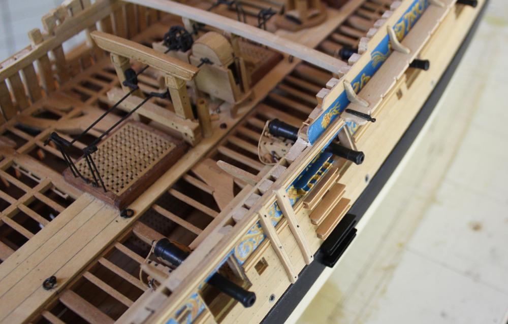
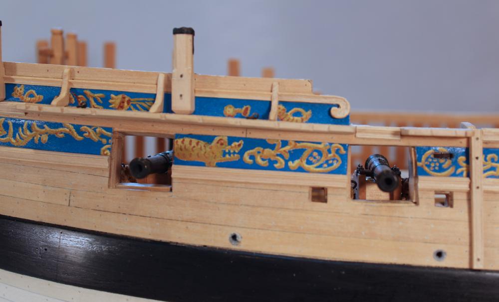
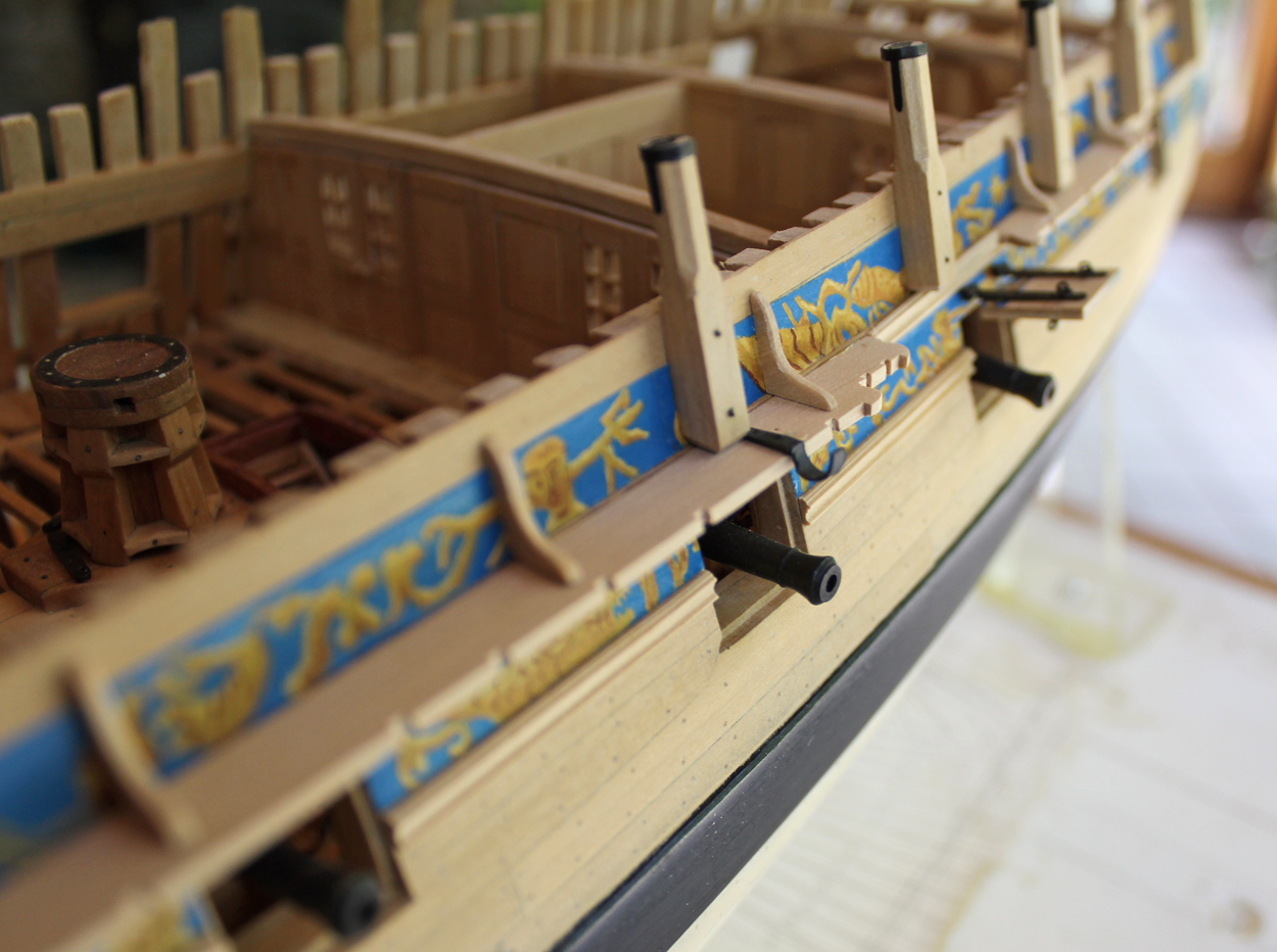
There are eight swivel gun mounts, three on the forecastle and five on the quarterdeck. Although identical in configuration, each one is different in length. I started with a 9" square stock and milled the top part into an octagon. Then, based on the plan, the final length of the octagonal section was determined and cut by hand. There is a shoulder transitioning between the square and octagonal sections and this was made with a file. The square section tapers at the foot except where it abuts the hull. It is installed perpendicular to the waterline and secured with two bolts.
There is a reinforcing strap and socket which accepts the mount for the swivel gun. In real life, this is recessed into the gun mount. In 1:48 life, this was made of acid free paper which was dyed with a archival black pen. I attempted to make a decent appearing hoop but decided the only way to get an octagonal hoop was to also use paper, wrapped three times around the gun mount to get the correct thickness (0.5"). I have also finally cut off the top timbers flush with the rail. I left them long to protect the top of the ship. Now, on the port side, the gun mounts will perform the same duty. They have temporarily been kept long on the starboard side.
-
I have gotten mine on EBay. Here is a current link. http://www.ebay.com/itm/Keystone-Plastic-Engine-Belt-8-9-Single-belt-for-Dental-Jewerly-Handpieces-/311610258678?hash=item488d6b34f6:g:694AAOSw1KxXM0QJ
-


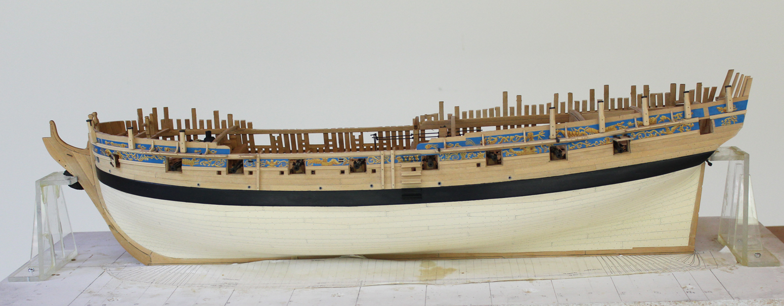
HMS Atalanta 1775 by tlevine - FINISHED - 1:48 scale - from TFFM plans
in - Build logs for subjects built 1751 - 1800
Posted
Yes, sir, it has. It won't stay that way long. I have a question about the foremost swivel gun mount. Should it be perpendicular to the water line or in line with the hull configuration?