
Captain Slog
-
Posts
904 -
Joined
Content Type
Profiles
Forums
Gallery
Events
Everything posted by Captain Slog
-
Is it a Russian Pernov type torpedo boat. From what I can tell they only have numbers, no names? Slog
-
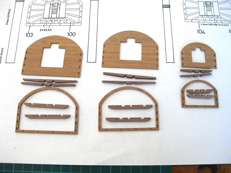
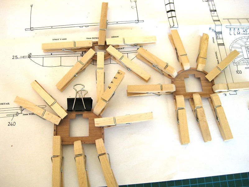
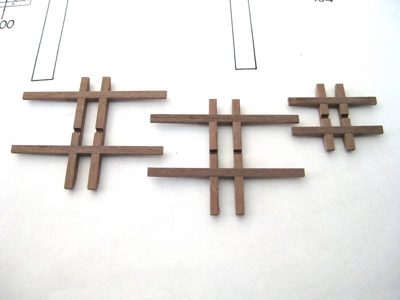
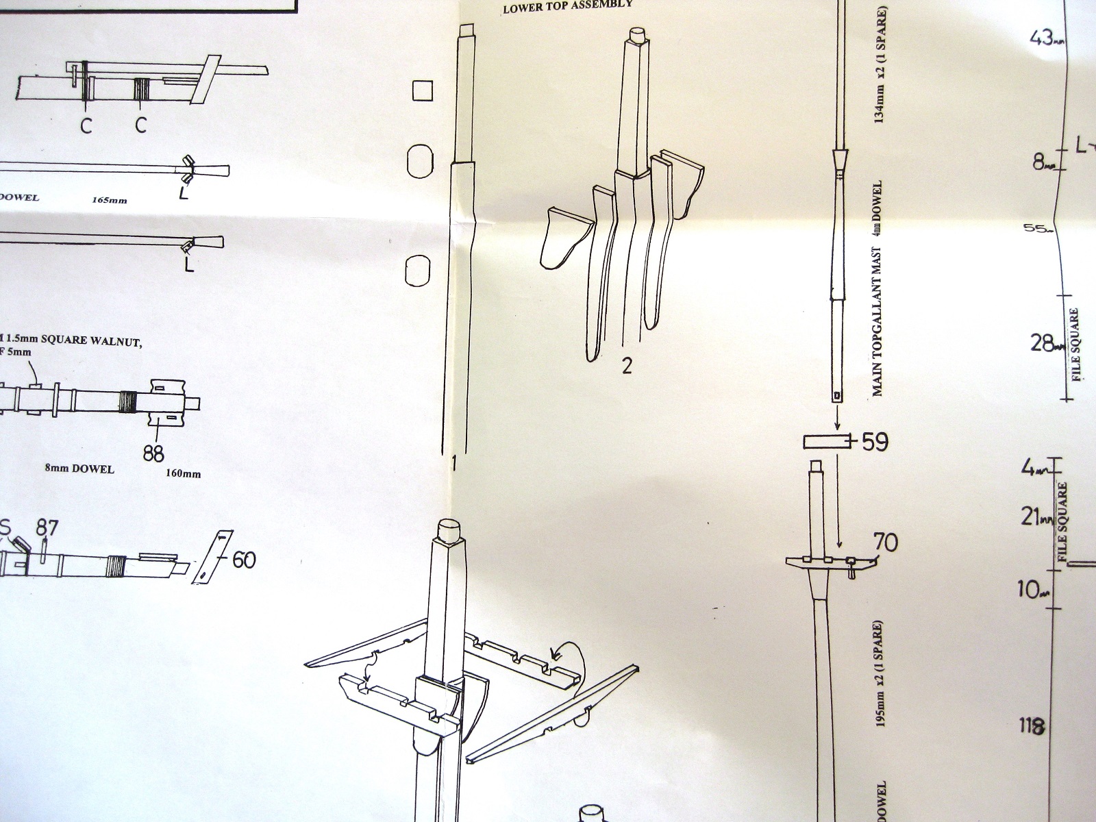
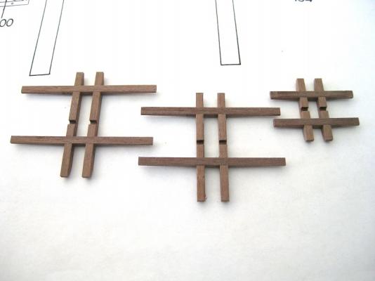
 Hi Guys It certainly hurt mine Just a small update. Thanks to your comments and a look at the plans and the mast instructions I have came up with a plan of attack for doing the masts/cheeks. I will follow the instructions except will try and do the hounds set-in/flush with the cheeks like you guys have done. Also the cheeks and hounds are from 1.5mm walnut ply which I will try and redo using some 1.5 mm lime wood strip glued together to get the width correct. This will allow me to stain and varnish the cheeks like the masts instead of them standing out a lot darker walnut. Made a start on the last of the major components from the kit, after the tops are done, apart from the rigging, it is only small bits and pieces left. The first picture shows the individual parts for the tops all cut out and cleaned up ready for assembly. The tops and batten surround are from 1.5mm walnut ply instead of individual wood deals but this is not a problem as they will be painted black. One thing which is annoying is you have to drill out the individual holes for the crows feet. Considering they drilled out similar holes you would think they would do these also. Here is the batten surrounds glued up and clamped to the tops with plenty of clothes pegs. The surround was a perfect fit to the tops. Whilst the tops were glued and drying I did the trestle tree and cross trees, which are from the 3mm solid walnut sheet. The slots required only a pass or two with a miniature file and slotted together nicely. These as glued up also. The next step, once the glue is dried is to carefully mark out the crows feet holes and drill them out using a 0.7mm drill as per the plans and then fit and glue up the many 1.5mm square battens that radiate out from the centre to the batten surround. Join the tops to the trees and install the rear hand rail. Cheers Slog

-
Greg and Steve, Thank you both for your patience and input in helping me with this, I feel a bit stupid actually. I will spend a bit of time going through, what you have posted, the AOTS and the CC plans and will come back with a proposed plan of action to run past you guys to see if I am heading in the right direction. Cheers Slog
-
man, this area is such a head (bleep). The flat area on the mast for the cheek - does it start from nothing and gets deeper until the full thickness of the cheek at the top?
-
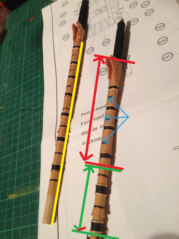
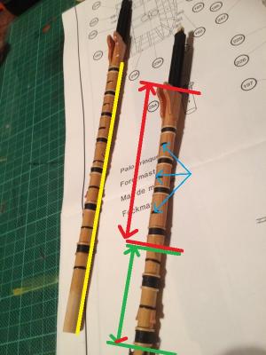
Hi Greg, I hope you don't mind but used one of your photos to make my questions clearer. The section between the green lines - This is the full circular width of the mast? The Section between the red lines - Does this section have flats on it like the CC plans ask for? or round? Does this section have a taper put into the round mast? The Blue pointed hoops - Are these cut between the Cheeks or are they full circumference with notches cut in the underside of the cheeks The Yellow line - Is this a straight line going right up the mast , along the cheek and the hounds or would it step out when it hit the cheek and step out again when it hit the hounds. (The AOTS shows a straight line upto the cheek and then a straight line along the cheek and hound page 84) Thanks for the photos, I think between your answers to the above and the AOTS I am getting close to the answer. The CC plans show the Cheek plonked flat on to the mast and then the hounds plonked flat on to the cheeks. Cheers Slog EDIT Hi Steve, You posted as I was writing the above. I am finding that whole area confusing. THanks for the photo I see you did a flat for the Cheeks like the CC plans I wasn't sure if this was the case or not. The drawings in your photo looks like page 84 of the AOTS. That is what I am aiming for as the CC plans ask for a lumpy layered effect where as that shows a nice smooth line. Thanks for the info. Slowly getting my head round this
-
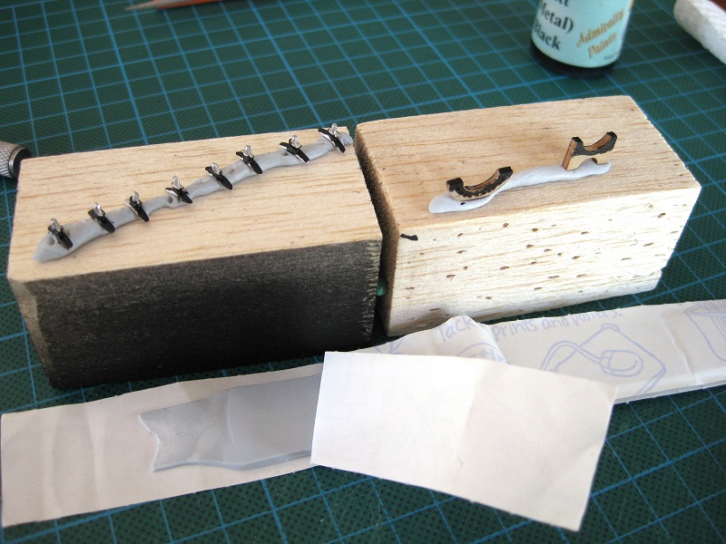
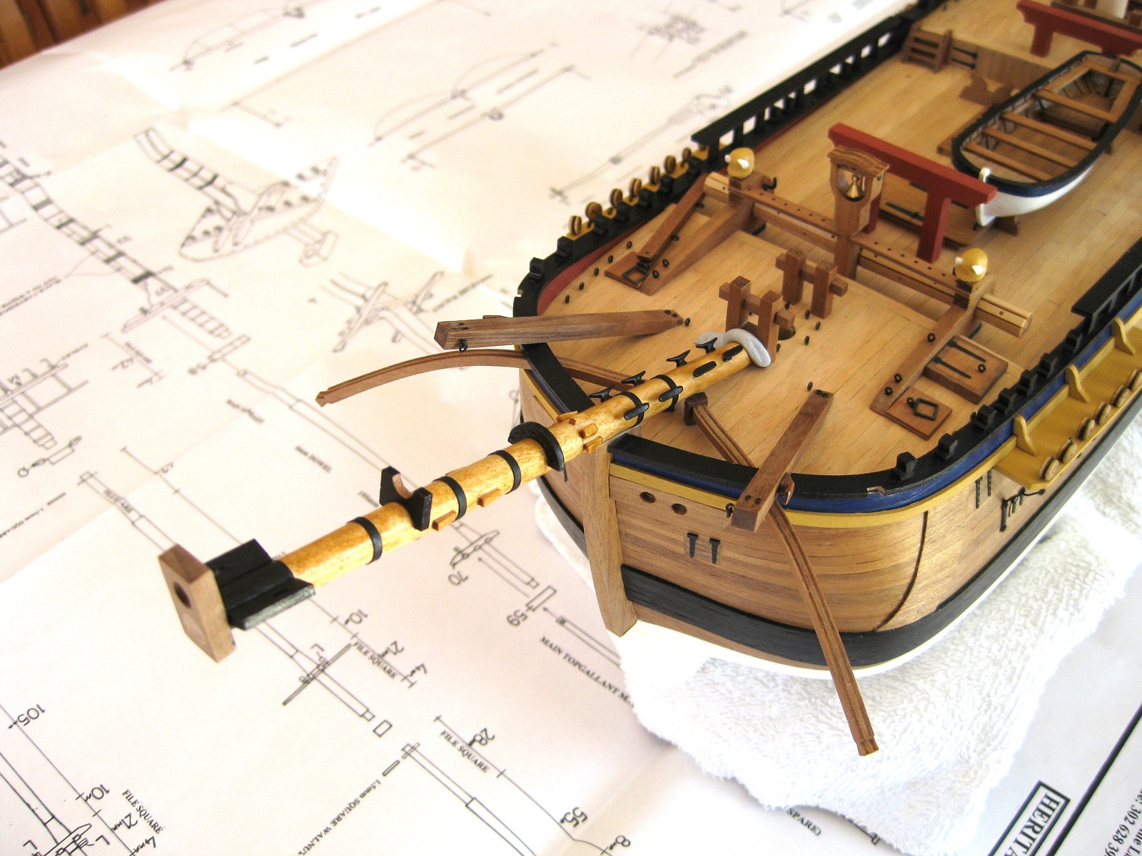
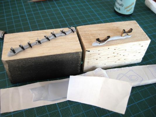
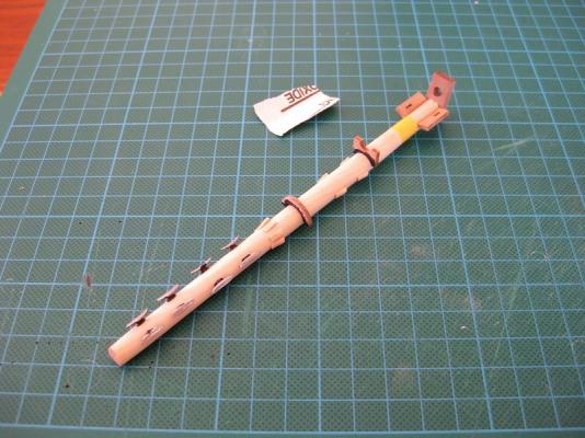
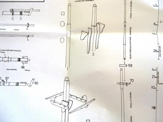
Hi Guys Greg I practically live there as it is! I included a picture of a strip of Blu-tac for Sam and showing it holding some of the small parts being pre-painted before installation. I only painted the areas which contact the bowsprit or would be hard to access after fitting. In this case the white metal cleats, jib-boom saddle and the fairlead. Once I marked all the positions of the components I drilled and glued on the various components to the bowsprit. I used Tamiya masking tape to mark the black paint line. Okay here is the almost completed bowsprit temporary in place. A few points of note, most of them bad! The dowel supplied in this kit does not take stain well as it appears quite blotchy in places. I used the black paper again for the hoop bands and marked the position on the BS from the plans but as can be seen one clashes with the stem (another lesson learned here, don’t rely on the plans alone). I also found it difficult to mark the positions of the cleat holes on a circular dowel. The eight cleats are in groups of 4 with the two groups being in different positions but the group nearest the deck aren’t very symmetrical. Hopefully this will be hidden once rope coils are going every which way. I also didn’t fully paint the BS Cap since I will need to do some filling once the Jib-boom is in place. Okay I now have a question for some of the masters out there (do you see what I did there?) LOL I am confused with the relationship between mast, Cheeks and Hounds/Bibs. The plans below show how you file a flat into the mast for the cheeks to sit on, then hounds go on top of these. Question, does the mast really have a flat, I assumed the cheeks wrapped partially around the mast and the hounds’ let in’ to the cheeks. From what I have seen the cheeks and hounds are all smoothed into one. Also the plans mention placing paper bands between the cheeks. Would these go round the whole mast and the backside of the cheeks recessed for the thickness of the hoops? A lot of questions I know but any help would be appreciated. Cheers Slog


-
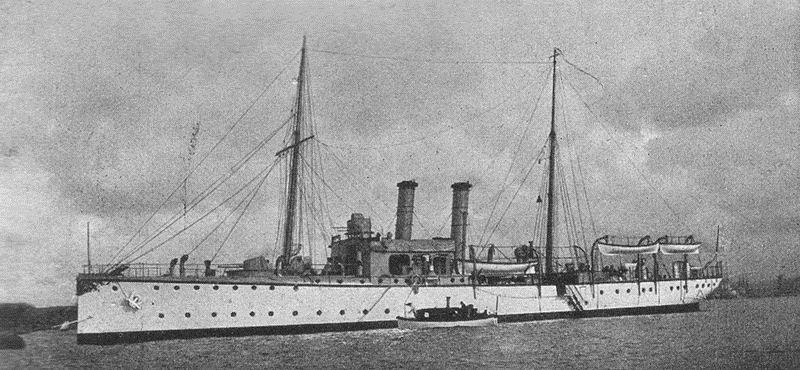
Hi Doreltomin, It is one of the Bayan Class armoured cruisers. The 'Admiral Makarov' laid down in April 1905 and launched in May 1906 (according to wikipedia. Your turn. Slog
-
Hi Jeff, As the others have said, definitely the yellow ochre. I got my Admiralty Paints from CWB with no problems and came quick as well and if I remember was cheaper than buying from Miniature Steam! Although that was few years ago now and not sure of the current prices. Cheers Slog
-
Getting there, Russian. Let me know if want a lot more clues as it appears I have 'beached' the thread! Cheers Slog
-
Hi Greg, won't have a problem with the new place. Got a whole spare room for modelling (can see 2 or 3 builds going at once then) and there will be plenty of display space. The titles for the block were just released, 2 months late and it will be ours on the 10th Jan and got a builder all lined up so just have to wait now. Thanks Jeff. Hi Sam, words from wikipedia "Blu-tack is a reusable putty-like pressure sensitive adhesive produced by Bostik, commonly used to attach lightweight objects (such as posters or sheets of paper) to walls or other dry surfaces. Traditionally blue (blu), it is also available in other colours" Very useful having blobs of it to stick things into for holding also. Cheers Slog
-
Hi Stuart, The 1st build of the Warrior on MSW and you torment us with one measly photo! Sorry, but what the others have said. Will be following this one with interest. Cheers Slog
-
Hi Jan, Not German. Built in France but not for the French... Slog
-
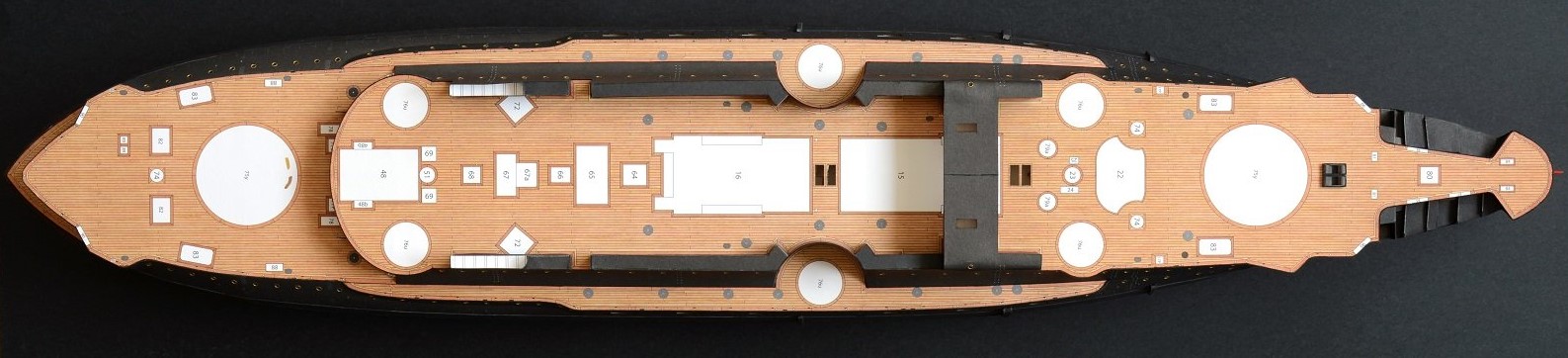
Its photos like these that make you wish there was an 'incredible shrinking' machine so you could walk through the cabins and sit at the table and bask in the luxury of it all.
- 883 replies
-
- 1
-

-
- royal caroline
- ship of the line
- (and 1 more)
-
Hi Jeff, The wales look good. They certainly add another 'dimension' to the hull bulking it up to a nice shapely form. I was going to suggest you might think about at least partially painting parts of the framework which may be difficult later but see by your comments your on to it. Cheers Slog
-
Hi Greg, Your Bowsprit and Cap is stunning. Mine won't come close to yours, going to do mine straight out of the box. I have glued the Cap on to the bowsprit and will glue the Jib-boom into place also. The plan from there is to attach all the bits and pieces, cleats, bees, fairlead etc, paint and stain and then pack away. Where the ship currently resides, doesn't have the space to have the bowsprit assembly fixed in place. I will move on to the masts, tops etc without the rigging and pack away also until we move to the new place at the end of the year. Then hopefully just the rigging to do. cheers Slog
-
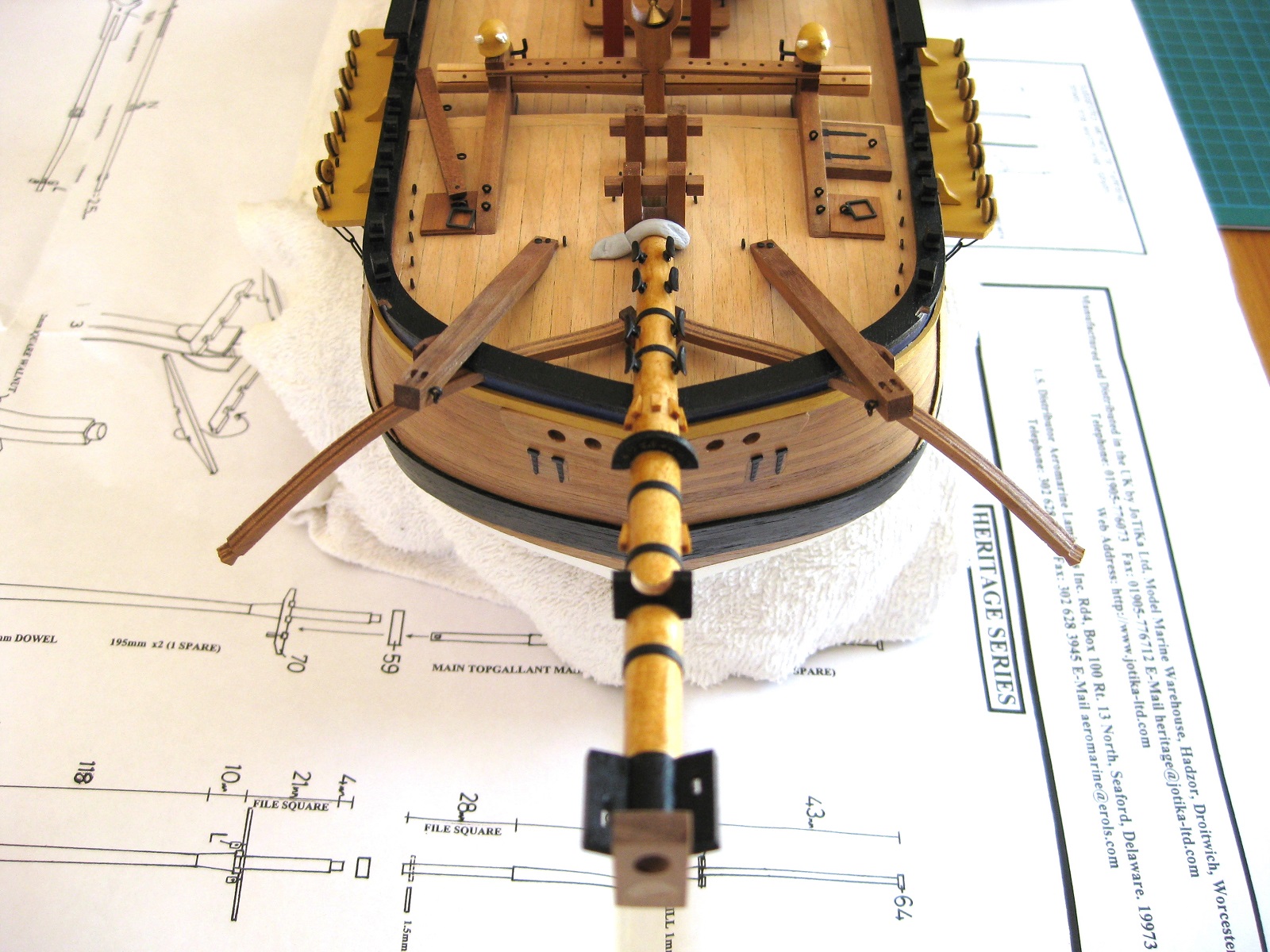
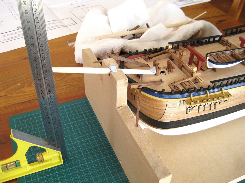
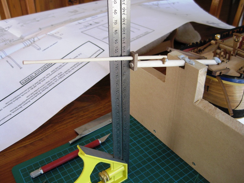
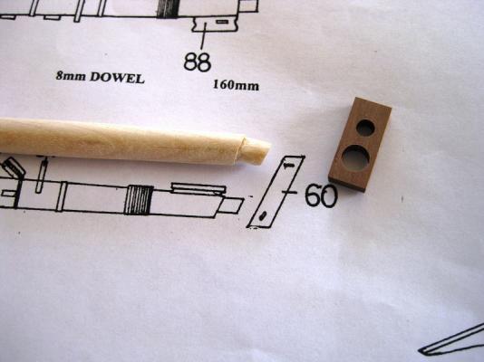
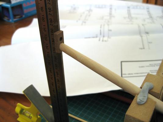
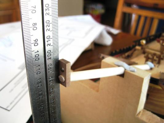
Hi Guys, Thanks for the comments. Right lets head back to the other end of the ship to work on the bowsprit. Previously I did a bit of work in positioning the bowsprit on to the stem post which was more or less there. Today I cut the Jib-boom from 4mm dowel and after checking the tapers against the plans marked the various transition points on to both dowels with masking tape and headed out to the shed to the drill press. Holding the Bowsprit and Jib-boom in the drill press and using various files and grits of paper I put the tapers into the Bowsprit and the Jib-boom. The bowsprit (BS) was left full width near the middle and tapered down towards the front and back. The Jib-boom was left full width until ti passed the Bowsprit Cap (BSCap) point and then tapered down to the front, leaving a section untouched as it flares out to full width again. On to the photos, I placed the hull in my MDF plumb and level jig so I can determine the position of the Bowsprit Cap. After securing the BS in position with Blu-tac I used the carpenters square to get the vertical position on the BS, since the BSCap is vertical to the waterline. Once marked up I started to cut the tenon into the end of the BS with razor saw and craft knife. Here is the BSCap, as can be seen there is a number of minor problems with it. Firstly I am pretty sure the mortise for the BS should be square. And secondly the JB hole should be on an angle to match the slope as this will cause problems which will be seen later. The photo also shows the rough ‘round’ tenon. Okay the BS in place and the BSCap positioned vertically with the water line as determined by the carpenters square. Photo 4 shows the round tenon sticking out. Once glued up I will trim to length and fill the gaps since it will be painted black and shouldn’t be noticeable that the tenon is round and not square. I did at one stage think about doing a fake square tenon on the end but since its being painted not worth the effort IMHO. Here is the assembly in place showing the shapely JB and the issue with the BSCap JB hole. If I fittedthe JB through the hole as is the JB would be parallel to the waterline! So I had to enlarge the hole to incorporate the angle of the JB to the BS so the BSCap hole becomes elongated and therefore not a nice tight fit round the JB. Again not fussed as this area is painted black so will fill the gaps and paint once everything is fixed. Currently the BSCap is glued up as per photos 3 & 4 and once dry I will continue fitting painting, staining the rest of the components etc. Cheers Slog


-
Hi Pat, Your Endeavour looks incrediable! I forgot how sweet your ship's boats look also. Thats a neat rigging station you have set up. I take it, its home designed and made? Cheers Slog
-
Thanks, starting to get my head round clues from the photos. If only I could pick more obscure photos, but going with what has caught my interest lately. Here goes... removed a flag from the stern

-
Hi Kevin, I assumed the sea water ports would be a Photo Etch supplied part? I wonder of flyscreen mesh which is glass fibre net would prove suitable, very thin strands and holes small enough to keep the mozzies out. anyway just a thought. Cheers Slog (PS I can post a picture if you like, didn't want to clutter your log)
-
Is it...HMS Minotaur? Slog
-
Hi John, Your Morgan is looking fantastic. I might have missed it but the ships name on the bow and stern are these decals that were supplied or something else? They look very crisp. Cheers Slog
- 2,250 replies
-
- 1
-
-
- model shipways
- Charles W Morgan
- (and 1 more)
-
Did I say a day? I meant an hour! I must be the worst player in the history of 'name the ship game' ever. Your are of course correct, SMS Panther it is. Cheers Slog
-
Wow, I am on fire, 2 correct in little over a week, who would have guessed Although I would never have gotten it without the rioting clue, which after reading your description is pretty disturbing. Okay, here is another which no doubt will only last a day...

-
Hi Dave, Is it the clipper 'Challenge' which caused a riot in San Francisco when they heard of the treatment of the crew? Cheers Slog