
Captain Slog
-
Posts
904 -
Joined
Content Type
Profiles
Forums
Gallery
Events
Everything posted by Captain Slog
-
 Congratulations Patrick on finishing. That is one very nice clean sharp looking build. Cheers Slog
- 299 replies
-
- 1
-

-
- niagara
- model shipways
- (and 1 more)
-
Well done David. Looking very sharp for a 1st card build. Cheers Slog
-
Looking very nice Wayne. These were my 1st thoughts also when I saw your new rail. Shouldn't be a problem for you though. Cheers Slog
-
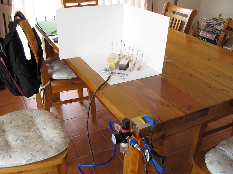
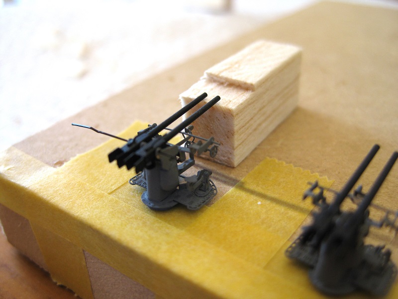
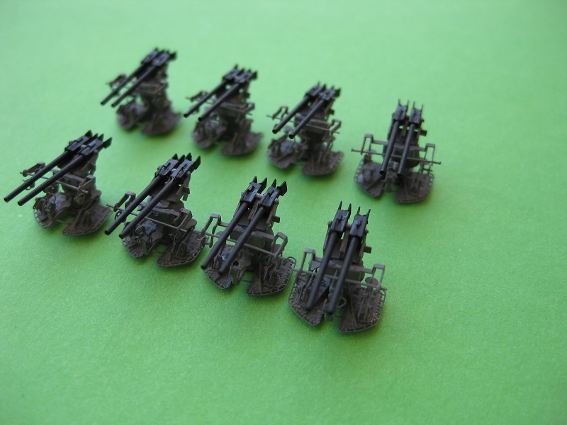
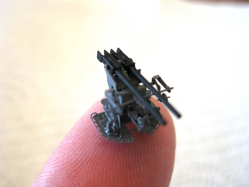
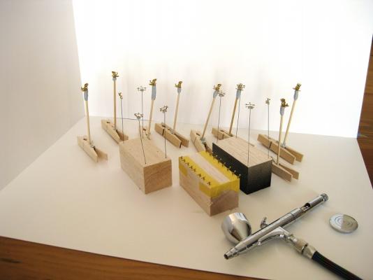
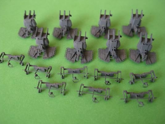
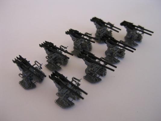
Hi Guys, Thanks for all the nice comments! and the likes. Hi rafterrat, the PE is very easy to bend being only 0.15mm thick and the fold lines are grooves etched into the surface so it’s a simple case of using a blade to hold the part down, just showing the bend line and then using another blade to pry it up. Thanks David not so sure about that though! Hi Greg it isn’t too bad on the eyes, but I find I can only do a few hours at a sitting before eye and hand strain set in. Thanks Sam but might leave that off for these…although you got me thinking about the main 15” guns! Okay the 37mm guns are totally finished as far as I am concerned and even packed away in a little storage container never to see the light of day again for who knows how long. The trials and tribulations at working at the kitchen table. I made a spray ‘booth’ out of some poster board to keep any overspray contained. The compressor was fired up and left in the shed and the airline run up the side of the house and in through the door to the filter/moisture trap/gauge which was clamped to the table. The parts were held in various configurations to hold whilst spraying. The main bodies were stuck down on to some blu-tac on the end of a bamboo skewer and then held by a clothes peg. The side assemblies were stuck onto blu-tac and then stuck into some balsa blocks with piano wire. These parts could be held by the wire and skewers and rotated when spraying. The side seats were stuck down onto some Tamiya tape along the edges of a balsa block with the arms hanging over the edge for access. Here are the main parts all sprayed up with Tamiya Dark Sea Grey. Other than a few trials spraying the lantern on my Endeavour this is my first real attempt at using the airbrush in anger and a few points of note I would like to make. The Tamiya grey was mixed 50/50 with Tamiya acrylic thinners and the pressure was set at 15psi although I turned this down a couple of psi as I progressed. The above set up and ratio sprayed beautifully giving fine lines to broader spray no problems. The spray worked perfectly during the whole time with no splatter or clogging even with multiple stops for a minute or two to swap over parts and I could have sprayed for hours like this. This is in total contrast to spraying the black barrels. In the morning I went to the local hobby store for Tamiya flat black but they didn’t have any so went home knowing I had Admiralty Paints Metal black. Admiralty Paints paint beautifully with a brush but DO NOT AIRBRUSH. Within a couple of minutes the airbrush would clog and splatter and stop then blast out full bore before clogging and splattering again. Not to mention the problems cleaning the airbrush at the end. The grey cleaned up in a few minutes! In the end I used the last of some Games Workshop Chaos Black spray I had in the shed. After I glued all the parts together and left overnight it was time to insert the barrels. I struggled for a long time trying to line up all the holes to feed the nylon bristle through to hold in place until I realised that the elevating quadrant was hitting the gun mounting. For the first 2 assemblies I bent the front sector of the quadrant to give more movement but this was difficult. In the end I used the craft knife to remove the front sector completely as trying to bend them was breaking them off and had to reglue them back on. Once the front sector was removed the barrels dropped right in and then wiggled about to get the bristle through. Once all the barrels were in place and the bristle slipped right through, I stuck the gun bases down on to masking tape and used a balsa block to set the heights of the barrels all the same. Then using a needle I touched some CA to the breech/mount/bristle to fix the barrels at height. Then I used nail clippers to snip off the bristles from each side of the mounting and a final touch up with grey and black. Although the macro shows I missed some bits and pieces. Guns totally finished and all laid out. Not bad for a first real attempt at constructing with PE (used PE in the Endeavour build but nothing like this) but could do better I think. As usual lots of lessons learned. Firstly shiny brass appears to look really good since CA glue dries clear you don’t really notice it until painted when it shows up in lumps and bumps and rough spots. Some of the bending could be better, especially the side arms but these are very difficult to hold and bend in multiple directions without disturbing previous bends. Overall I enjoyed the experience and like I mentioned I have the 20mm cannons to do but might have a break for a weekend or two. I should be ordering the hull forms and another ‘kit’ book next week so will be a relief to work on something that can be seen without being 3 inches in front the face LOL Cheers Slog


- 107 replies
-
- 14
-
-
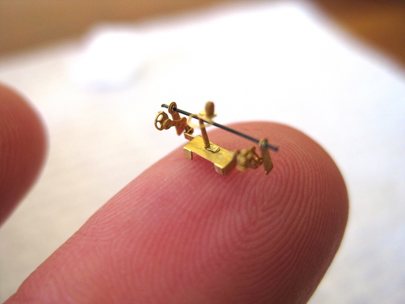
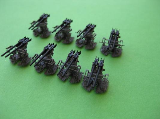
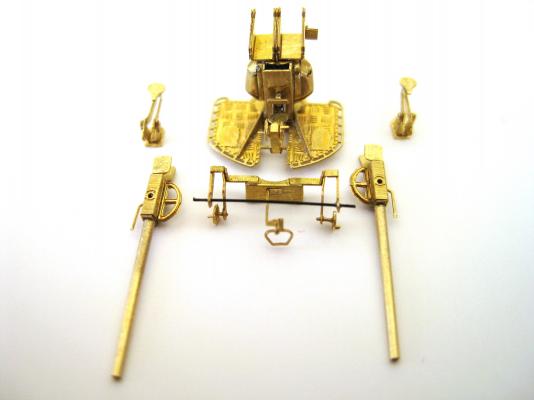
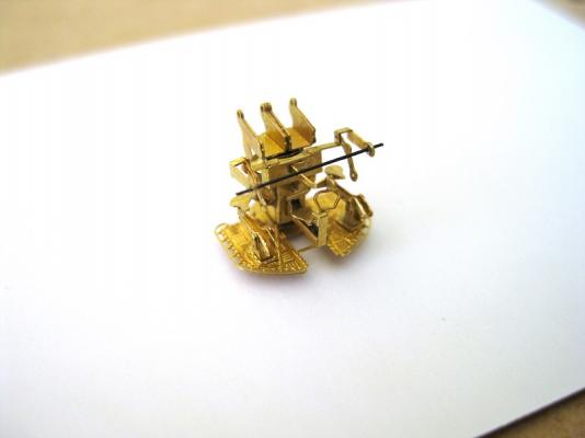
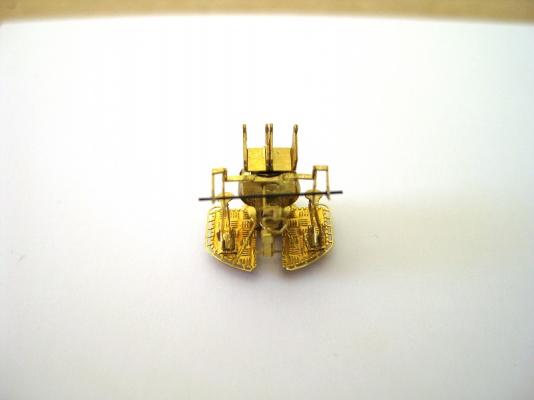
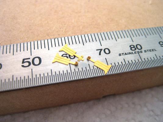
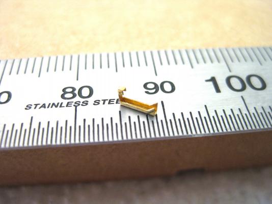
Hi, David, already lost some parts. Thankfully only needs 8 guns so 2 spare of everything Right, that’s the construction of the 37mm SKC/30 Dopp LC/37 cannons finished and ready for paint and final assembly. The side (elevation?) hand wheels were fitted into the holes mentioned previously on the side arms. This was a major pain. The tube/bar on top of the breech, although the half the size of an eye lash was pretty straight forward. At first glance they could be mistaken for a sight but I don’t think they are. The AOTS shows them in a reverse position and lying down flat so who knows. The 2 central (traversing?) hand wheels were the last part to be glued to the central seating position and pretty quick and easy. Couldn’t help but layout all the assemblies to make 1 gun ready for paint. Just remembered after paint there are a couple of bars to be made from brass rod which fit to the front of the side seating positions. These aren’t supplied but given the length and where to attach them. They appear to be some kind of shock absorber. Total of 48hrs with each gun containing 65+ parts. I haven’t ordered the laser cut hull bulkheads and forms yet so if I finish painting these next weekend then it will be on to 12x 20mm single cannons…oh joy I can hear everyone groaning from here. Cheers Slog

-
Hi David, I heard/read/was told that card modelers also use water colour pencils. They look like ordinary coloured pencils but the 'lead' is quite waxy feeling and dissolve slightly with water. I didn't really get the hang of them and will try 'almost' dry brushing with acrylic next time. Cheers Slog
- 50 replies
-
- 2
-
-
- kingston class mcvd
- finished
- (and 1 more)
-
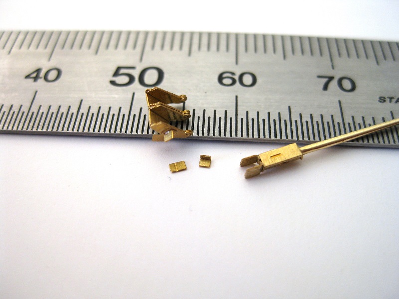
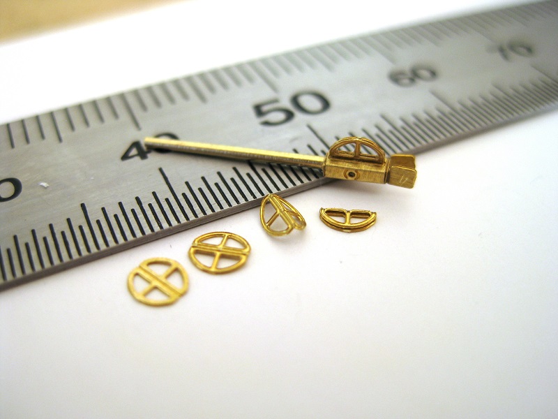
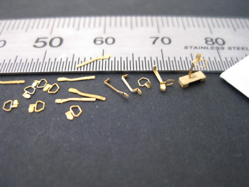
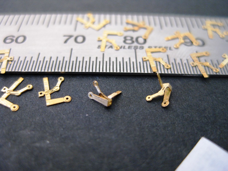
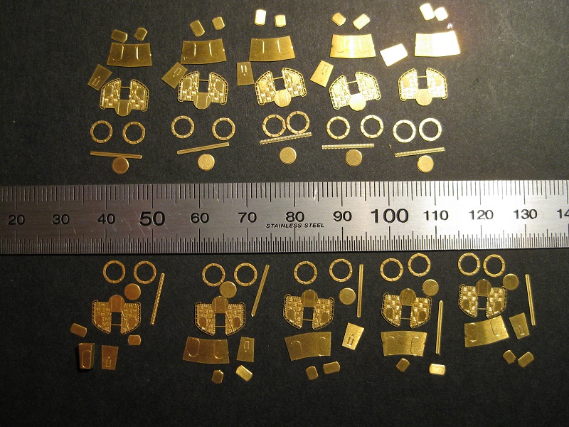
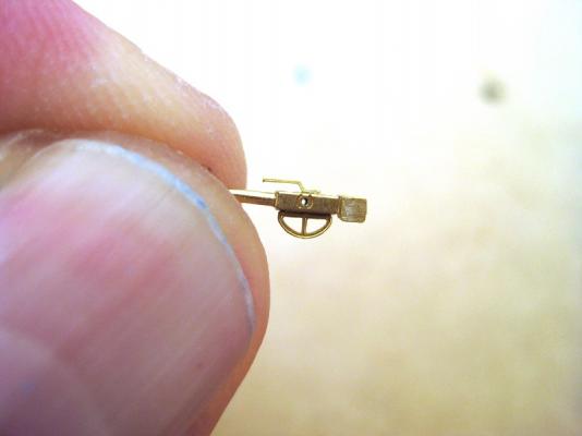
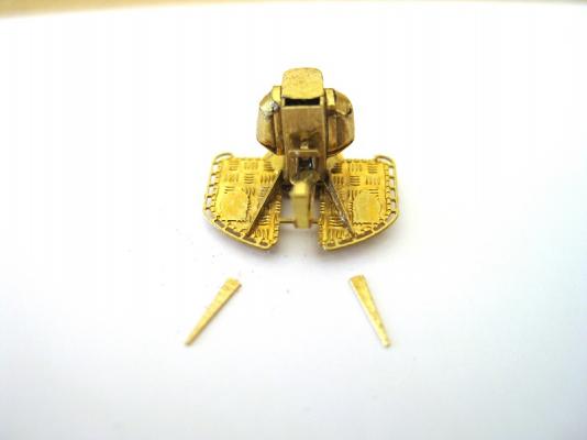
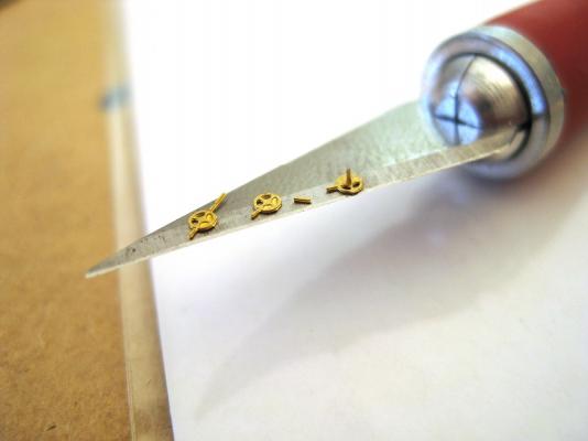
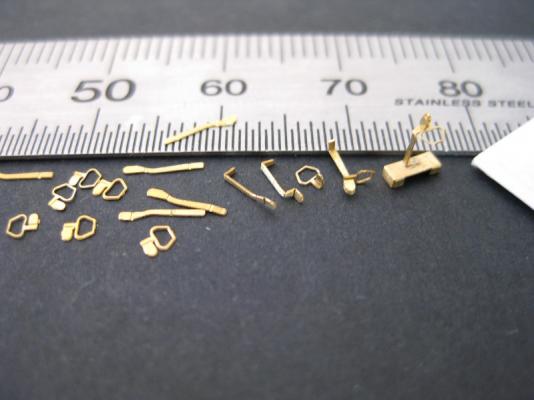
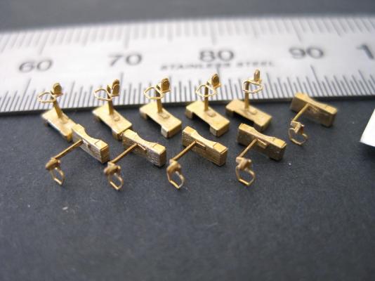
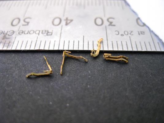
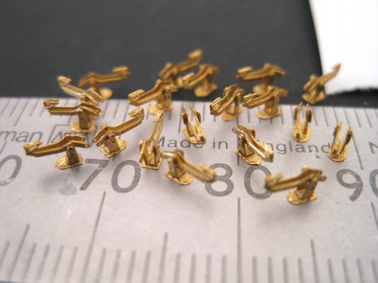
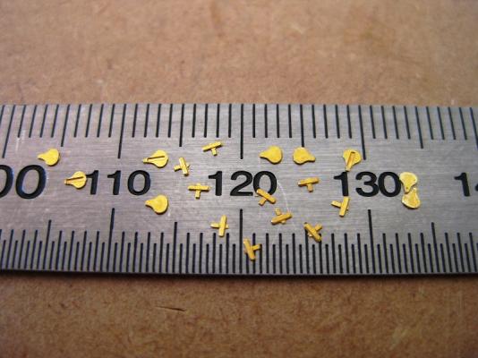
Hi All, Thank you all for the comments Thanks David I am pretty chuffed with them although as usual lots of areas for improvement. Thanks for the kind words Doris. If your Bismarck is to the same standards as your current build then I can only imagine it would be a stunning example. I doubt I will reach your level of skill in this lifetime considering I still haven’t actually done a card model except for a few bits and pieces which I am going to redo. Hi Grant, it gets worse Wait till you see the hand wheels below! Unfortunately who can tell when they will be fitted? I haven’t actually did any real card work yet. Hi Steve, I think you are correct about painting before final assembly. There are too many sticking out bits to guarantee full coverage. Really on to the home stretch now and finishing off the little bits and pieces. First up is a little angled plate which is fitted on to the left hand gun mount only. Simple bend and glue job. Wish I could say the same about the 2 plates on the end of the gun breeches (guards?). These were a nightmare to fit. There is the tiniest little flange which I assume is supposed to be bent to 90 degrees but the glue area is so small for a sticking out vulnerable part. I can think of a number of ways these could be better designed. The base plate ribs were again straight forward, if not a little bit fiddley. The gun elevating quadrants were straight forward and the picture is self-explanatory. There is just little pipe/tube/something to fit to the top of the breech to finish these. There are 2 types of hand wheels used a pair of smaller ones for the central station and larger singles for each side. I was a bit confused when I saw them at first until I realised what I had to do with them. Not sure if someone at GPM is playing a joke or messing about to see if anyone is stupid enough to build these but… The parts are on a No.11 blade. The first wheel on the left is how they are removed from the sheet. The little prong on the bottom left is the handle and this gets bent up to 90 degree to the wheel. I expected this (and the central position hand wheels just have this handle to bend up)but I couldn't work out the prong top right. Then it dawned on me that this was the hand wheel spindle to fit into the hole on the side parts shown in a previous post. The second hand wheel shows the spindle removed and lying next to the wheel. The last wheel shows it turned upside down to reveal a tiny dimple in the middle to glue the spindle too; I just need to bend the handle down to finish. Only another 15 more of these to do. Total time to date is 45hrs. I started off doing all ten but the parts war of attrition brought this down to the required 8 guns. There is probably another 2 to 3 hrs work left before paint. Probably works out around 5 to 51/2 hrs per gun. Cheers Slog


-
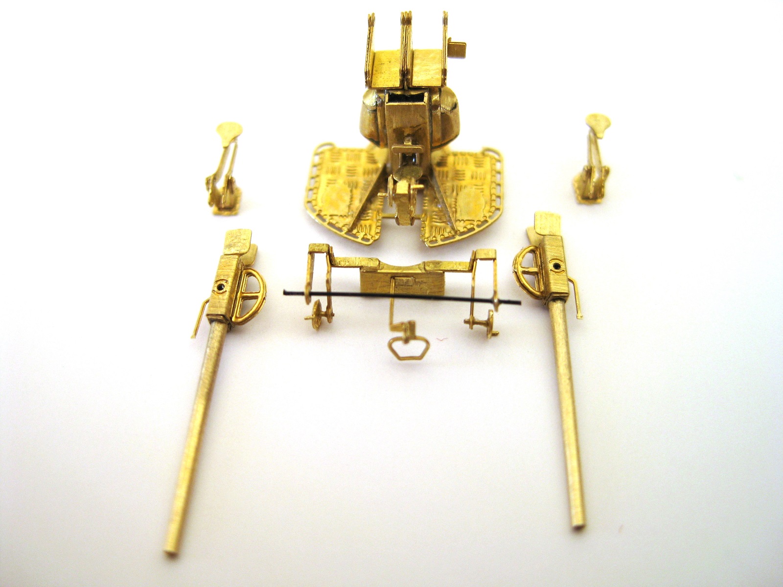
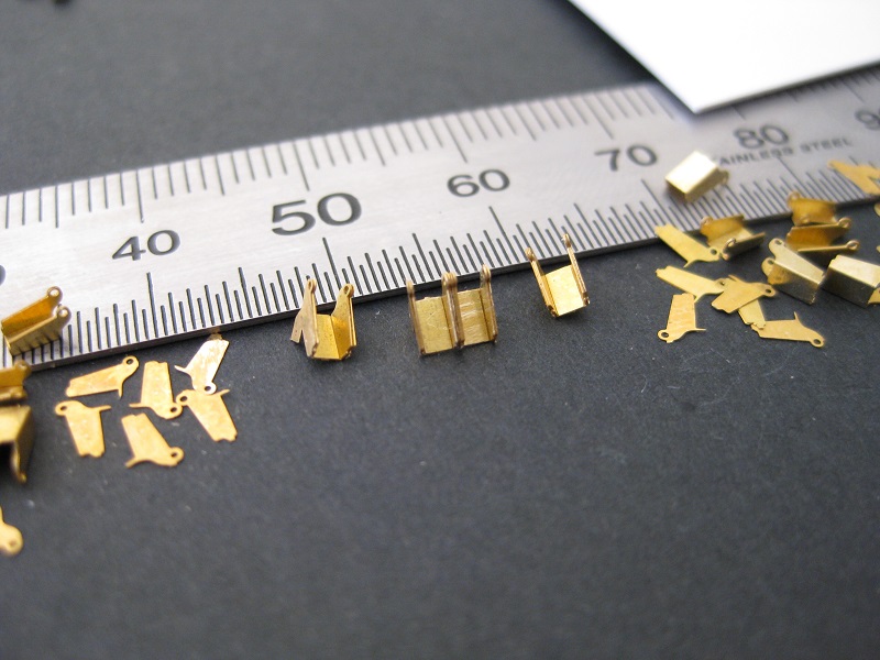
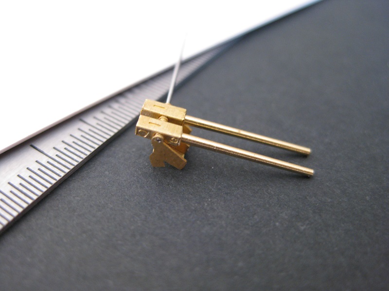
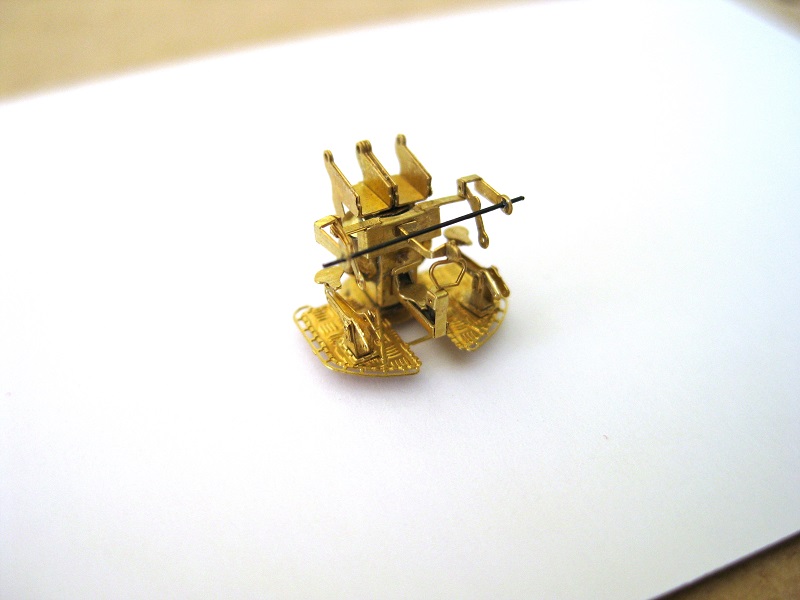
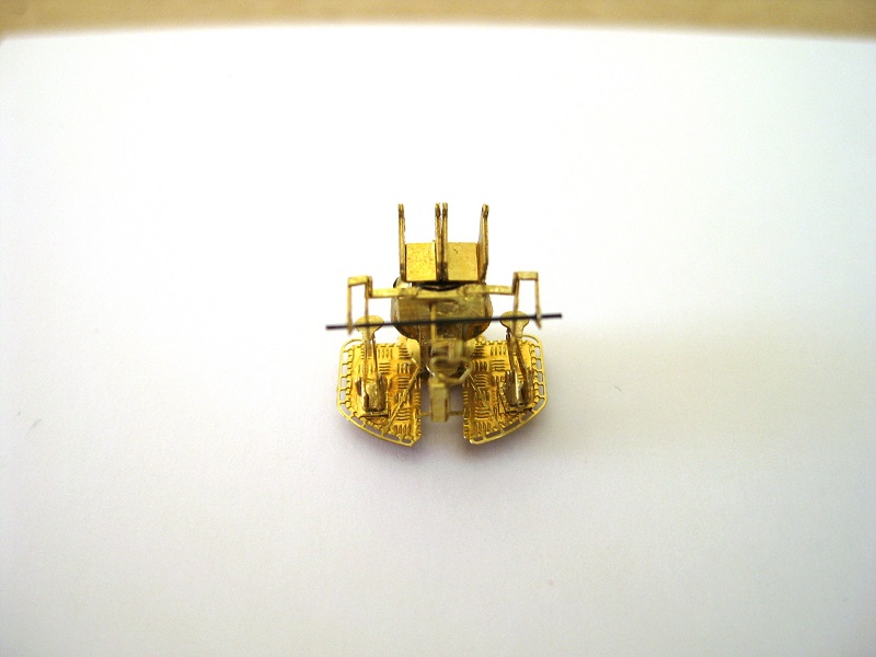
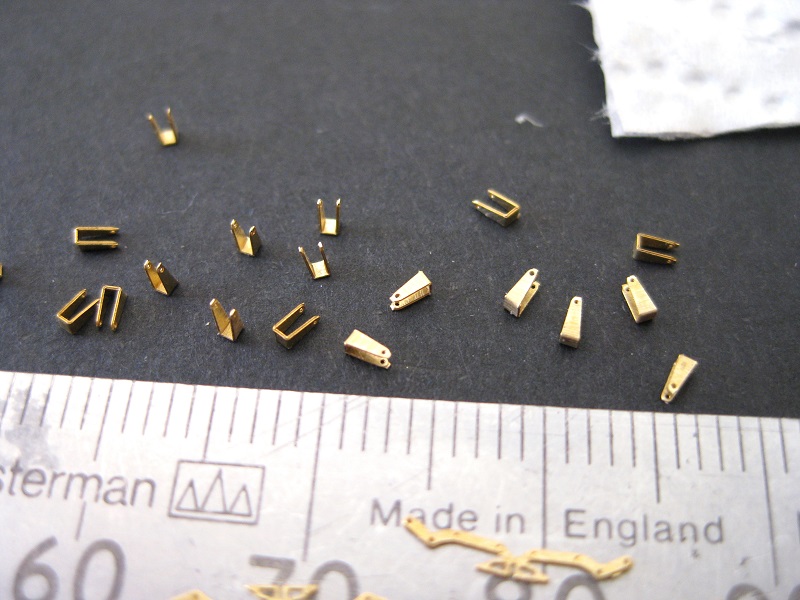
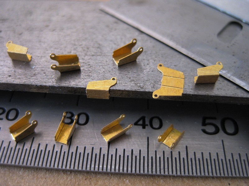
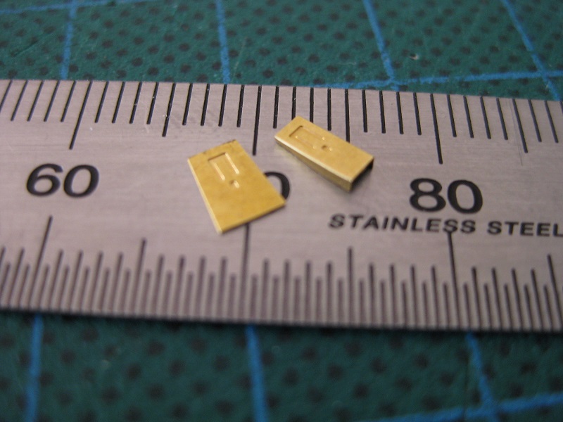
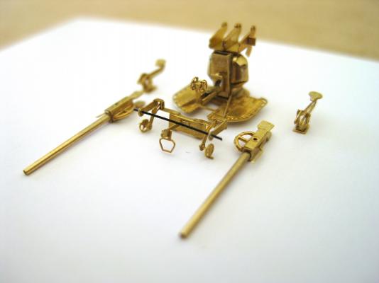
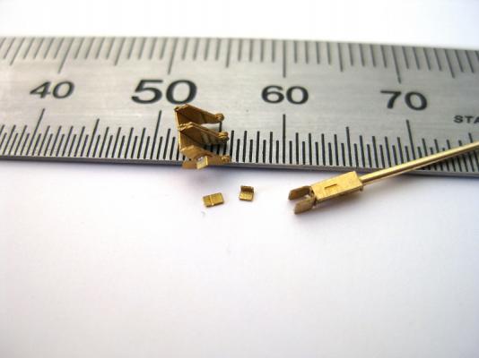
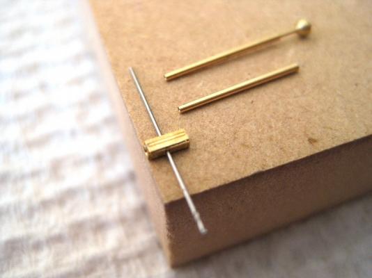
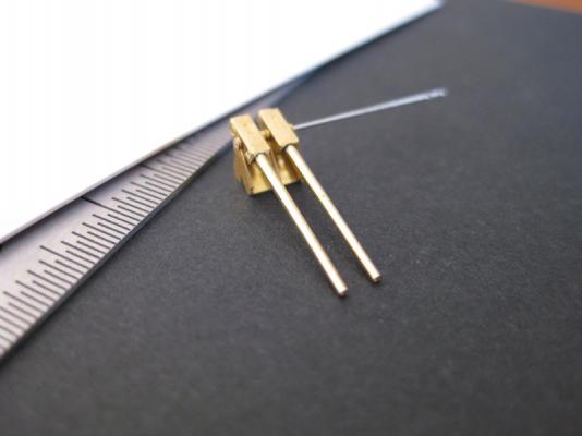
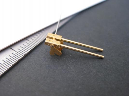
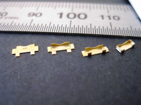
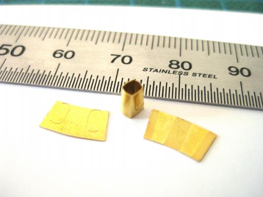
Hi guys, Thanks for the likes and comments. David, I will be airbrushing them with Tamiya acrylic Dark Sea Grey, which seems like it matches a lot of the superstructure colour. Can’t decide whether to spray the individual assemblies before or after final assembly. Not sure how the spray will get into all the nooks and crannies if fully assembled before painting. Rafterrat I just use the MK1 eyeball or the Admirals reading glasses if she isn’t using them. Glue wise I have used 2 part epoxy, CA (superglue) and what I assume is a gel superglue but the pack doesn’t mention CA at all. I think you only need to worry about CA fogging up clear plastic. Doesn’t seem to effect the brass at all. Also the amounts of glue are tiny, applied with a needle. Moving on to the guns now. The gun breech starts like everything else as a flat part. The photo shows from left to right the progressive bending to form the rectangle box which is the breech. I previously bought the gun barrel set which includes the 37mm barrels. I stopped making the remaining 2 guns as they supply 16 barrels to make the 8 gun sets needed so got a couple of extra bits and pieces. The brass barrels more or less match the diagram length wise but they only go as far in to the breech as the pivot holes. I placed a 0.2mm drill bit through the mounting holes so I could push the barrels in up to this point so I didn’t block the mounting holes and barrels are the same length. I also had to bore out the front hole to 0.8mm to match the replacement barrel diameter. The gun mounts are made in handed pairs. Each mount has a central U-shaped part with a plate on each side, and then the left and right handed mounts are joined together. I used the 0.2mm drill slid through the mounting holes of the central U-shaped part then applied CA glue to the outside face and slid the end plate over the drill. This was placed on to the central part, quickly aligned and then squeezed with tweezers for a few seconds. The process was repeated for the other side plate. Once each mounting was glued up it was tweeked to shape to square up. Then the drill bit was slid through a left and right handed mounting before gluing and squeezing together to form a pair. Photo shows left and right handed mounting with final pairing in the centre of the photo. A pairs of guns placed in a completed mounting with the 0.2mm drill holding it all together. When final assembly comes I will use a 0.2mm nylon bristle as used previously to hold everything. The guns themselves still have an elevating quadrant to fit on the underside, a couple of breech guards and a pipe of some sort on the top. Quick mock up to show how the guns are going to look. As mentioned not sure if go to this stage before painting or paint individual assemblies. The end is in sight now. Still to do on each gun; 2 bracing ribs on the base plate. 4 handwheels And 4 parts to finish the gun breeches as mentioned above. Cheers Slog

- 107 replies
-
- 10
-
-
Hi Colin, Looking nice. Does this 'kit' come with a full hull or is it waterline only? Cheers Slog
-
Hi David, You are making good progress. Cheers Slog
- 50 replies
-
- 1
-
-
- kingston class mcvd
- finished
- (and 1 more)
-
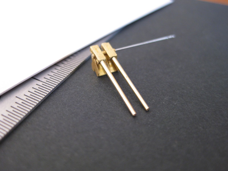
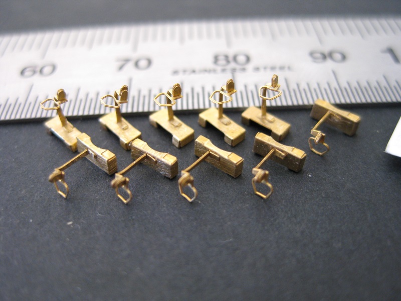
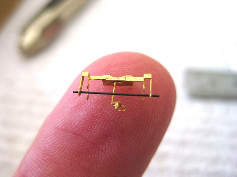
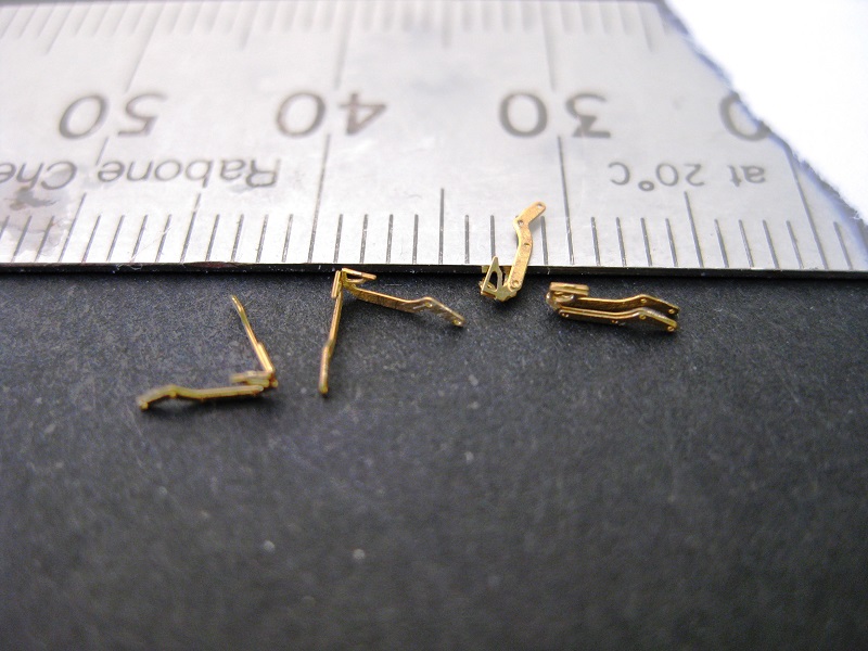
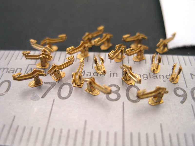
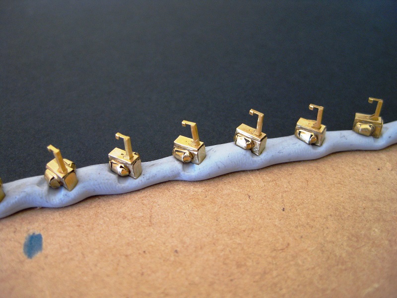
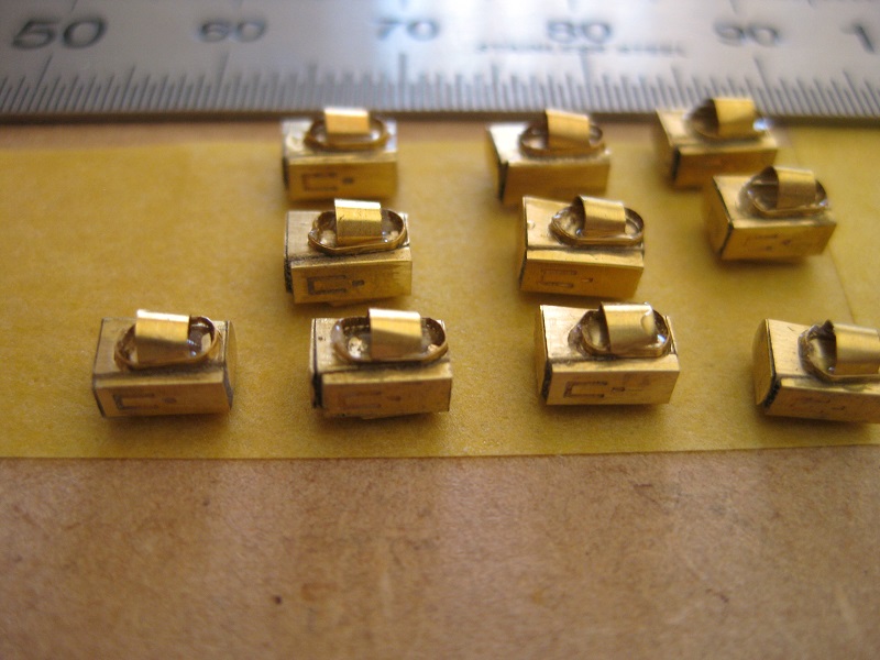
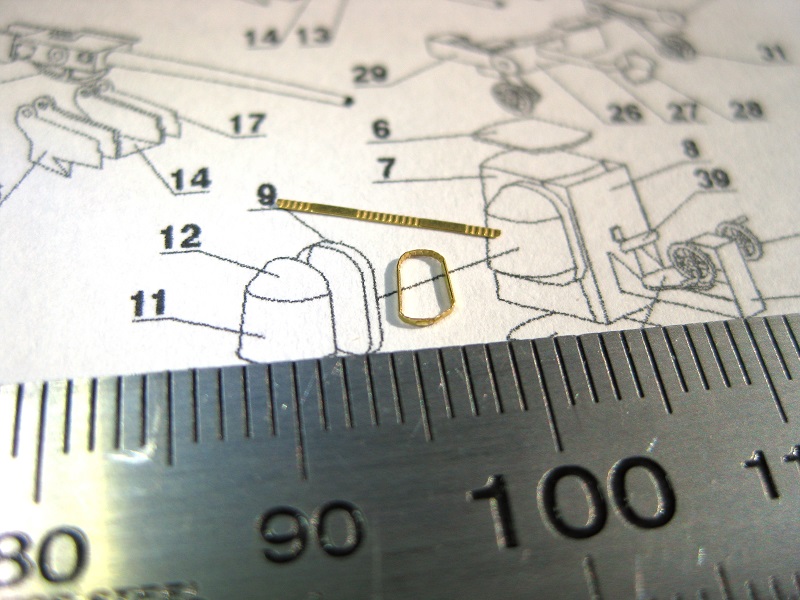
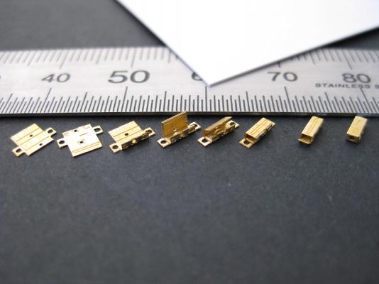
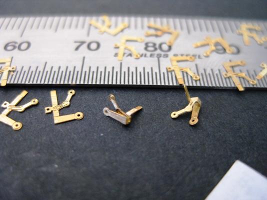
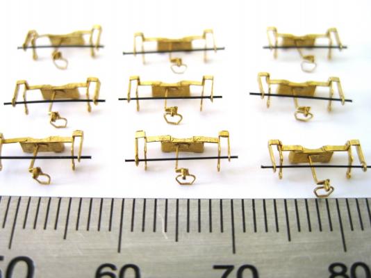
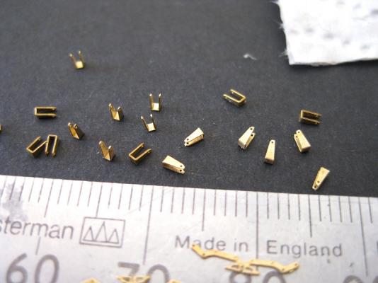
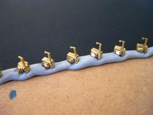
Hi guys, Thank you all for the likes and comments. I wish I knew what the various parts are called. The next parts to be done appear to be some kind of centre handle. This consists of a central bar and a handle. The centre bar has 3 bends in it and the handle has a single bend. The handle and bar are glued together and then fitted to a notch in the box from the previous post. These were pretty straight forward. All the centre bars glued to boxes. In this shot you can see how the bent flange of the handle isn’t fully lined up with the end bend of the bar. Whilst joining them they looked to the naked eye as lined up properly, only the macro shows the true extent of misalignment. Again at this scale all painted and in place you will never see it. The boxes from the photo above also hold the side hand wheel assemblies. These are handed left and right and I struggled to work out from the drawing the proper shape and relied on just bending on the etch marks. I think the picture may have the left and right numbers the wrong way round as part 29 is supposed to fit on the left (looking at the gun from the front) but after bending appears to be for the other side and vice versa. Notice the holes in the parts, 2 of these are actually used which I will cover later. The side hand wheel assemblies are glued in placed. The assembly diagram shows some kind of brace or torsion bar which stretches between the two side assemblies. They don’t provide this part but have length for it. I wondered what to use as I only have 0.5mm brass and 0.4mm piano wire which is far too thick for the aforementioned holes. By chance I noticed a little novelty keyboard cleaning brush in my sons room and after a quick measure the nylon bristles were 0.2mm thick and fitted the etched holes perfectly. Out with the scissors and the brush got a quick haircut. After feeding the bristle through the hole a small dab of CA glue secured them then trimmed to length. They are supposed to poke out each side. Hopefully another 2 or 3 sessions should see them finished. There are 4 hand wheels to attach for each gun set and the guns and carriages themselves left to do. After that I will try airbrushing all the parts then final assembly. Cheers Slog

- 107 replies
-
- 10
-
-
Hi Steve, Looking forward to following this build. Cheers Slog
- 625 replies
-
- 1
-
-
- bounty launch
- model shipways
- (and 1 more)
-
Hi Steve, Funny you should mention that, I have started using a pair the Admiral has (only +2 i think) which she uses for reading fine print on competition labels. Only thing is make sure to use them in private...I look like Mr Magoo and can't walk around as can only focus 3" from my face LOL
-
Hi Greg, Nice work as usual. I think your buoys turned out very nice and particularly the rope work. I'm being a bit thick here but the 2 outside anchors in the photo above have the holes in the correct orientation (hole parallel to the stock and 90 degrees to the flukes) and the one on the right looks like the Caldercraft ones I have so not sure what the problem is...unless the CC ones you got is the centre one then should be easy enough to fill the wrong hole with epoxy and re-drill the hole in the correct side. Cheers Slog
-
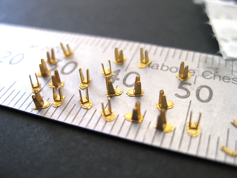
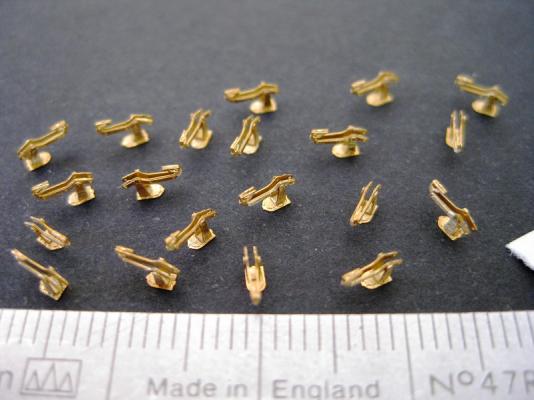
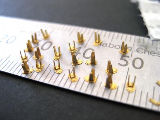
Hi guys, Continuing with the side seating assemblies; next up was to bend the seat rails together. This was done in 3 steps. Firstly was to hold the part by one leg and gently fold until resistance was felt around approx. 90 degrees. It naturally bent on an etched fold line. Using verniers I found that one of my steel rules was the right thickness so holding one leg against the rule I squeezed the other leg until it was parallel then gave a final squeeze with some tweezers. The last stage was to squeeze together the seat post whilst still holding the legs together on the rule. To glue the seat rails to the uprights I again used some Tamiya masking tape with the sticky side up and placed the bases with the upstands in a row. Then using a needle applied some CA glue to the inside tops of the upstands and then using tweezers placed the seat rails between the 2 uprights. Because the bases were pretty secure to the tape I used tweezers from both sides to wiggle the part into position before the glue set. The tiny gussets on the outside tops of the uprights was placed holding the base in tweezers in one hand then using a needle in a pin vice; a dot of glue was applied to the top outside face. Using another needle in another pin vice I then picked the gusset up by pushing the point of the needle in to one of the holes and placing it on the glue. The gusset, on touching the glue is pulled off the needle and then slide into final position before the glue goes off. The eagle eyed among you may notice that there are only 19 seat rail assemblies in the photo 3. After doing all twenty rails I noticed I had glued the seat rail the wrong way round on one of them so gently separated the pieces. I was holding the upstand in some tweezers and was cleaning the old glue off the base when it pinged out. I heard it hit my open tool box (fishing tackle box) so methodically went through each compartment followed by surrounding area in ever bigger arcs to no avail. Since I have lost one seat anyway it is no big deal and still brings me down to 9 guns but as Chris pointed out I only need eight so won’t worry. The seats were glued to seat rail assembly by placing the seat upside down near the edge of the MDF I work on and then grabbing the assembly with tweezers, applied some glue to the top of the seat post. Turning the assembly upside down I brought the post down to the seat which sticks to the glue. Right side up I tweek the position of the seat before the glue goes off. I placed a couple of seat assemblies onto a base to see what it looks like. I will probably paint the seat assemblies separately before fixing to the base plate as it is starting to look very busy. The next assembly to tackle is a box like structure which sits at the top of main gun body. I think the gun elevation controls attach to this as there more hand wheels to attach. To fold the flat PE into the box I started by bending the long side up first followed by the side and end tabs to form the ends. Once bent to shape a squeeze here and there with tweezers closed them up nicely. I use some eyebrow tweezers for final squeezing as they have flat broad ends which support the surfaces of the small tabs over a larger area. Cheers Slog
- 107 replies
-
- 10
-
-
Hi Wayne, Good to see you back on the build. The new curved pieces do look a lot nicer. Cheers Slog
-
Hi, Chris you are correct. I was looking at the card equivalent and noticed they only do enough parts for 8 guns. After reading your post I checked the AOTS to double check and yip only eight. I will pick the best 8 but considering I have already lost 1 seat and 1 front panel the decision will probably be made for me! On to the 2 side seating positions. 100 parts cut out ready for assembly. The upstands are bent to shape. Same method, hold the part down with a stanley blade on the fold line and then slide a razor blade under the part and bend up. And glued to the bases. Cheers Slog
-
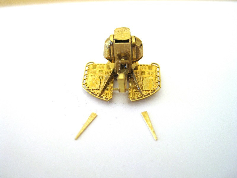
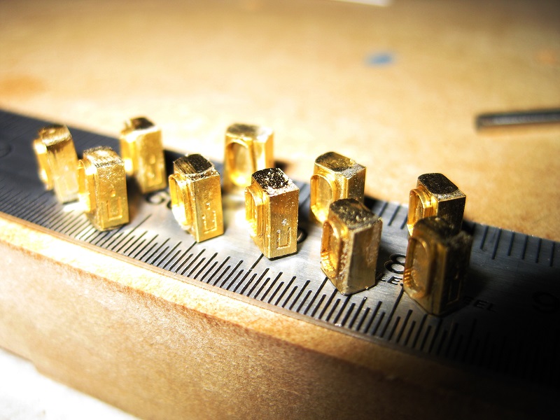
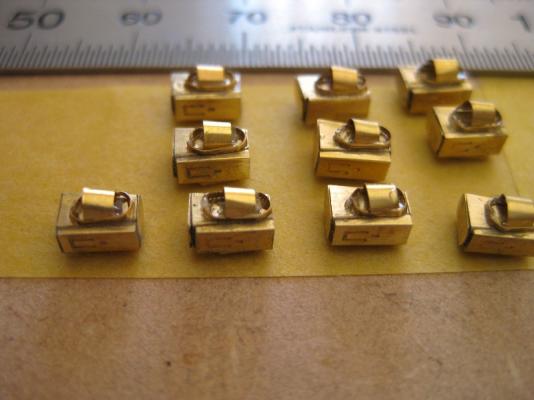
Hi guys, Thanks for the comments and likes. Continuing from the last post I glued the other side cabinet doors and glued in the tops and bottoms. These didn’t really fit that well and after a clean-up with some files there are a few gaps. Not to bothered again due to size and also some of the gaps are underlying epoxy. Also when the rest of the ‘clutter’ goes on and painted should be okay. Now the main parts of the bodies I moved on to the central seating position which I am guessing controls the transverse movement of the guns. The other seating positions on each side I am guessing are the elevation controls. The central beam is of course flat and needs to be bent to shape. Firstly was the end gear box which requires 3 sides to be bent to form a box (hand wheels will fit on each side of this) Next was to bend up the 2 side ribs (this forms a U shape which fits into a corresponding etched U on the front panel).Lastly the front gear box was bent up to finish the arrangement. Once all the bends were made I used a needle to place some CA glue down inside between the front folded vertical and the side ribs to stiffen it up as the strip with the box on the end is very thin and flimsy. The Bodies were pressed in to some blu-tac to hold them still then I diped the end of the central beam into some CA glue dispensed onto scrap card. The ends fitted into the etched U shape as was left alone to dry. After a few minutes for the CA to go off I used a needle to plce some epoxy into the U shaped area where it touches the front panel. Next up was to cut out the central seat and back rest. The back rest was probably the worst part to fit yet. Its like a T shape with the back pin bent at 90 degrees to fit into a little etched relief. The part is really small and trying to get tweezers into the area was nigh on impossible. The seats were epoxied to the central ribs. Main bodies with the central gun training position fitted to the base plate. Next up will be the 2 outer seating positions. Cheers Slog

-
Hi Rod, Your first layer planking and particularly your deck turned out very nice. As for your questions I personally would put the keel, stem and stern on next for the reasons you suggested unless there is something in the construction that needs to be taken into account. Not sure about using epoxy though. A wood to wood PVA joint is very strong if done properly and the excess can be wiped away with a damp cloth or cotton bud, particularly important if varnishing instead of painting. I think epoxy is very messy and cleanup difficult which will show under stain or varnish if not cleaned off and if left to harden is very hard compared to the surrounding wood so sanding it down is likely to thin the surrounding wood. Cheers Slog
-
Hi Guys, Thanks for dropping by with the comments and ‘likes’, much appreciated. Chris, perhaps multimedia would be more appropriate I am holding off doing the card parts since I want a more structured build starting with the hull and working up to the superstructures. I have to hold off doing these as not sure what is covered with the laser cut forms so will have to wait until I get them. The guns are a time filler until then. I might do a card one for comparison at the end. You provided invaluable advise the 1st time round so hopefully you will keep an eye out this time also. Also your 8 part series in the card thread got my interest up again and was most helpful. Okay it was time to form the body cabinets. These were bent to shape from the flat ‘petals shown previously. Got to say it was very difficult getting the width correct as they essentially sit on the thin perimeter. Once bent to shape I used some Tamiya tape, sticky side up, to hold the bodies still, whilst I needled some epoxy into the centre area and then placed the cabinet doors on. Problem is I now need to leave well enough alone until it sets and I can do the other side. The size and shape aren’t very consistent and the widening of the cabinet from top to bottom isn't as pronounced as it should be but honestly, I think once finished up and painted no one will notice them at viewing distance on a ship 1.2 metres long! Leaving the bodies aside to set I glued the base plates to the pedestals. They look okay and I like the effect of the bases lifted up off the deck. There are plenty of other bits and pieces to work on whilst stuff dries so made a start on the gun carriages. (by the way I am just making up the names of these parts to what I think is appropriate for describing ) I gave the outside face a rough up with sandpaper as doublers are glued to these. Luckily for me the blade of my engineers square is the correct thickness for the centre section. So it was a case of pressing down on the part with the square blade and then using a single edge razor blade to slide under and prise the sides up. A quick tweek with the tweezers finished them off. I am no expert with photo-etch but discovered a good tip which may prove helpful as it works for me. I only ever cut the PE on a piece of MDF. Since the surface is relatively firm all the blade cutting force goes into cutting the brass. I found cutting PE on a cutting mat distorts the piece to some degree since the mat deforms/sinks/bends initially before the blade starts cutting thus deforming the part. MDF has no give so no distortion. I guess the MDF is harder on blades but for all the above I have used the same no.11 blade and it’s still serviceable so far. Cheers Slog

-
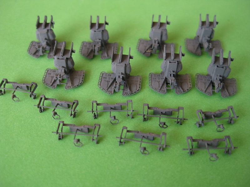
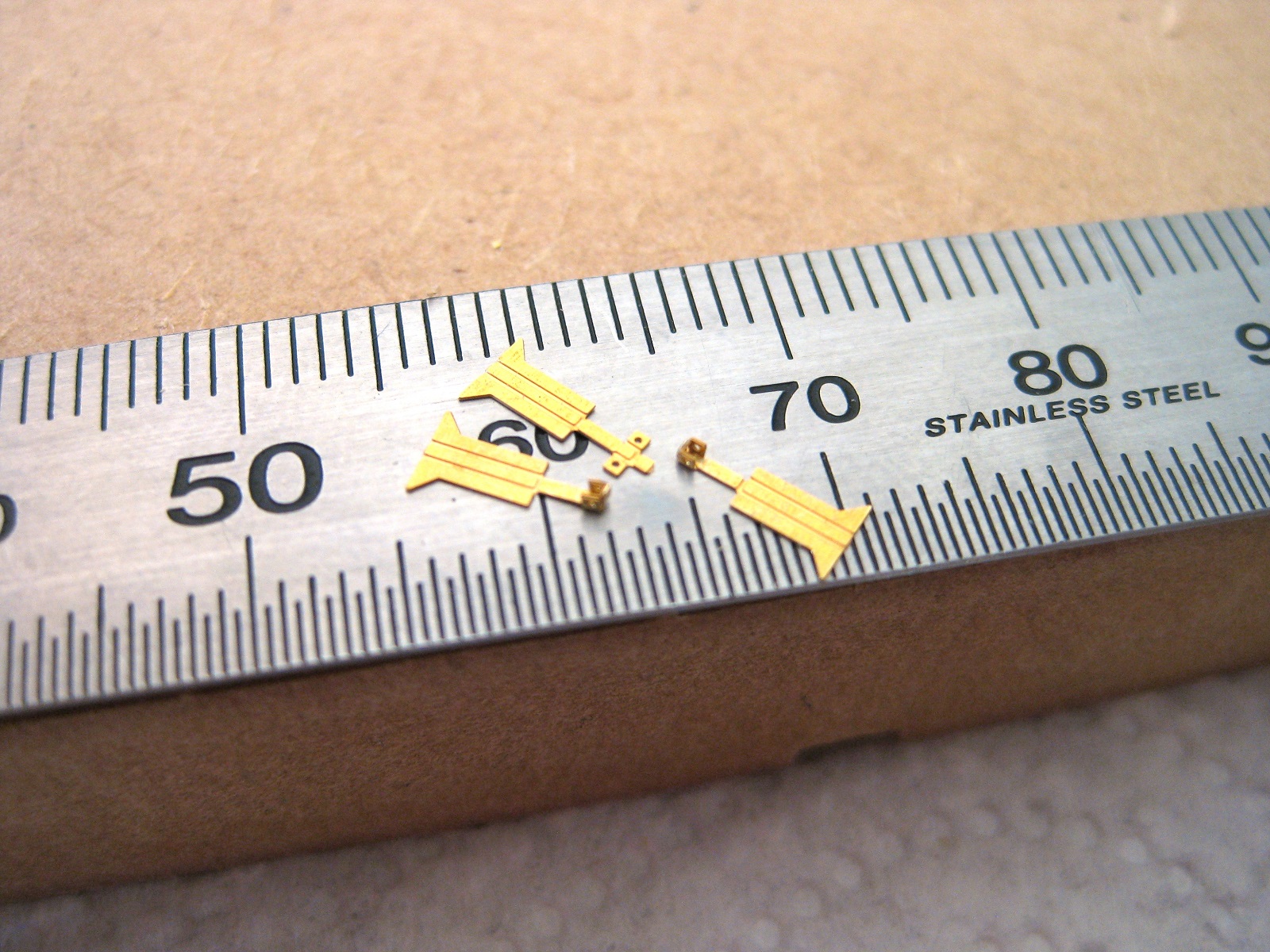
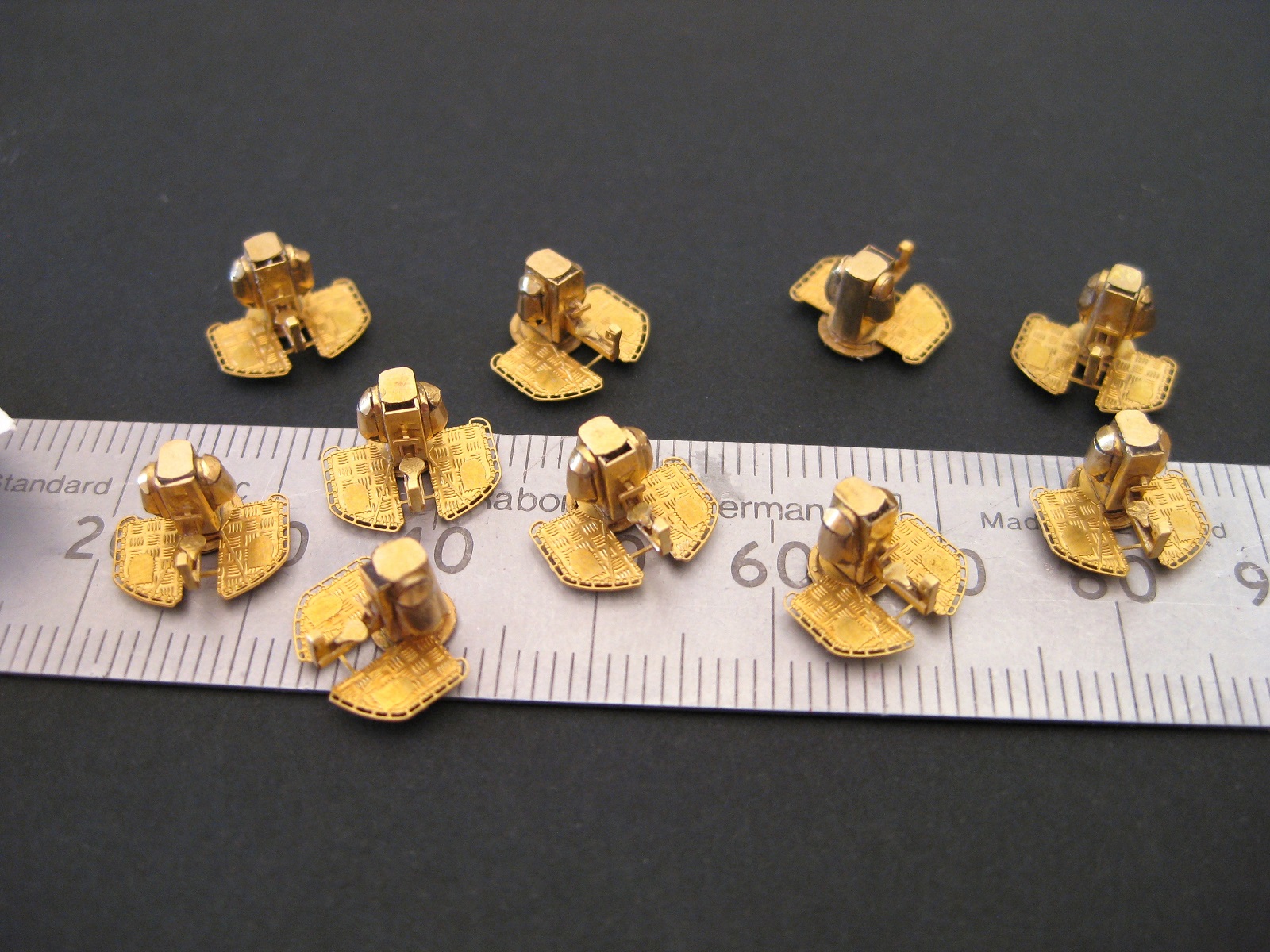
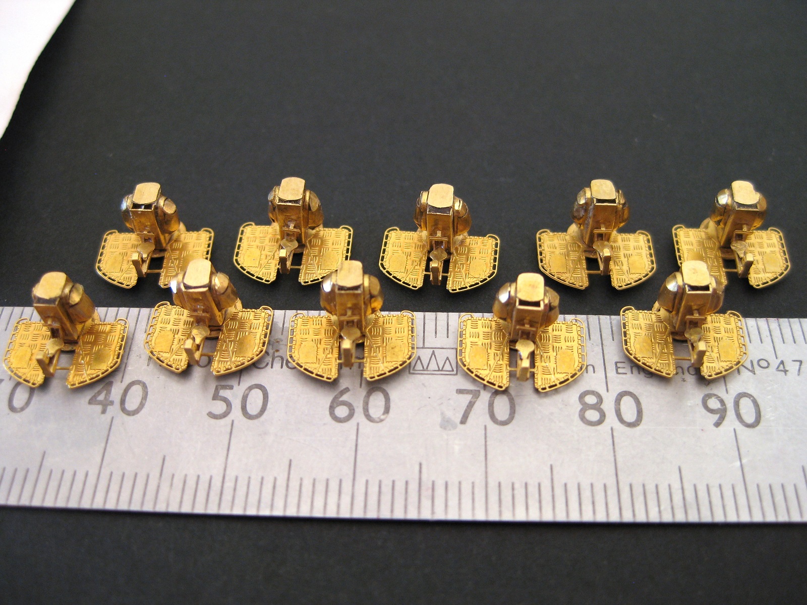
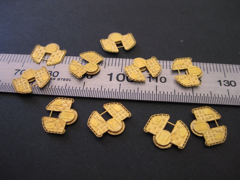
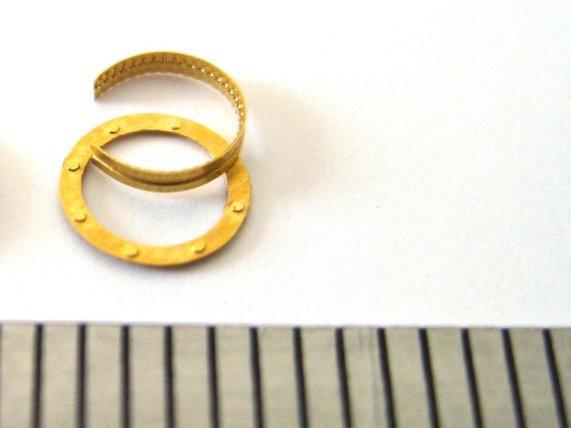
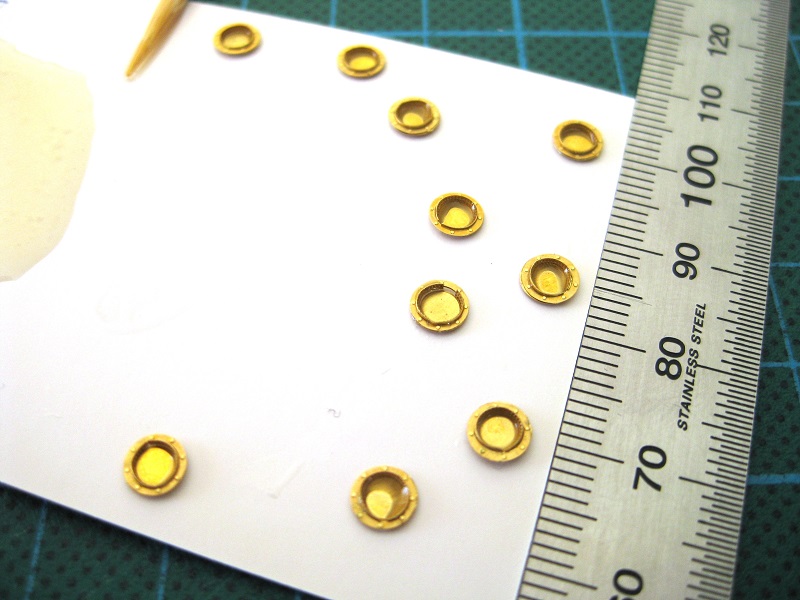
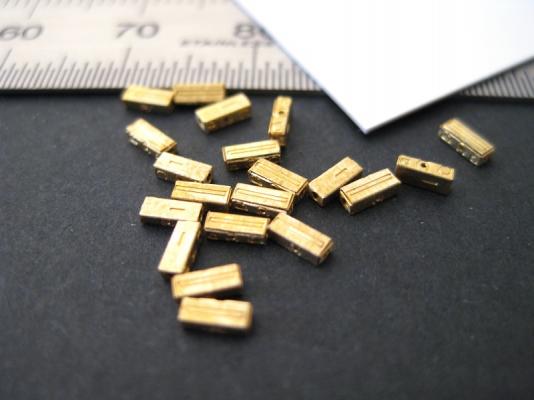
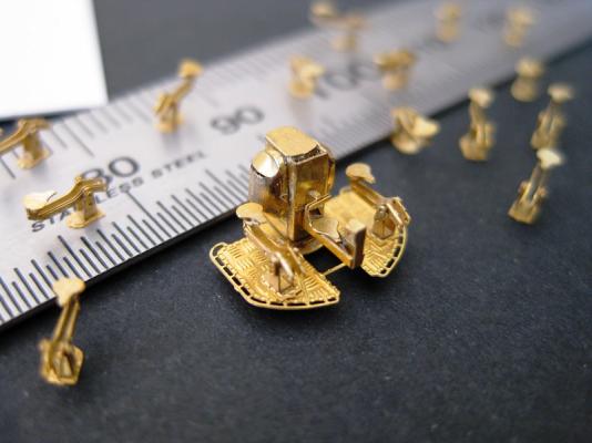
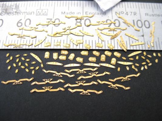
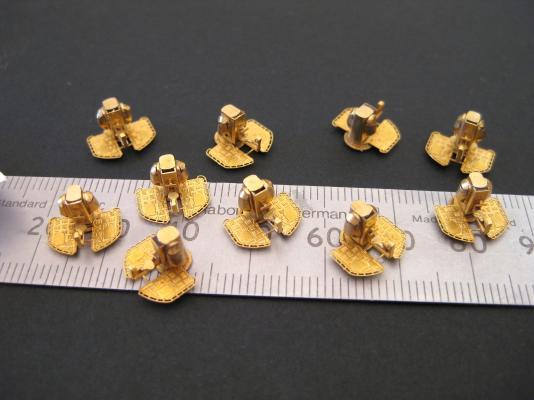
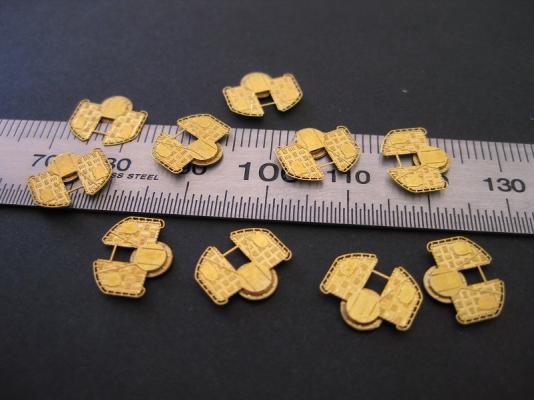
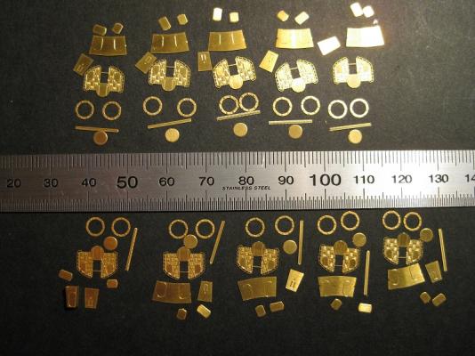
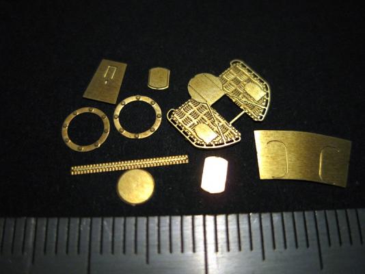
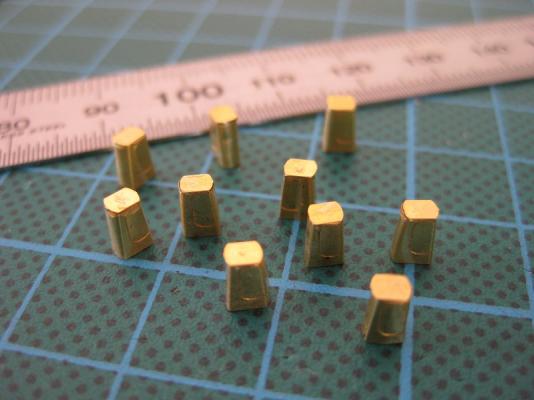
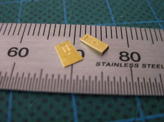
Hi All, Since I won’t be ordering the replacement book and laser etch frames to start the hull again until the end of Feb/March I decided to work on the photo-etch 37mm twin cannons. As mentioned above I had 2 sheets of photo-etch each making 5 guns giving a total of 10. One gun assembly consists of 65 individual parts and since I am doing all 10 at once I will have eventually cut and glued 650 parts Starting from the bottom up, parts 1 to 8 make up the mounting pedestal, the base plate and the main body. All 10 assemblies cut out and cleaned up. Close up of the components for starting 1 gun. The etch on the base plate is quite impressive considering its size. It shows a perimeter rail and checker plate pattern. The pedestal is made up of a circular base, a flat strip and a couple of flanges. It took a bit of head scratching where the bolted flanges were supposed to go but a quick look in the AOTS made it obvious. The two flanges were glued together then the flat strip was bent round a drill shank and placed inside the flanges. The strip has a groove down the middle which the inside edge of the flange sits in. Then it’s a case of gluing the circular base to the bottom of the strip. All the pedestals completed. I filled some of the internal cup with 2 part epoxy as the CA didn’t like holding the circular base to the edge of the strip. The main body which sits on the base plate is bent from a single panel into a rectangle and the top and bottom is closed off with little end caps. All the bodies bent and the end caps glued in. Again I used epoxy to secure the end caps. Using epoxy is slowing the build as usually have to wait several hours or the next day before can clean it up. CA although quick isn’t suitable for parts where I need to clean up with files etc. Once the end caps were on a good filing cleaned up any sticking out edges and flushed everything down nicely. The front panel is a single plate which needs the sides bent to sit on to the main body. I actually lost one of these panels. I have no idea where it went. I thought to only make 9 guns and get another sheet when I order more stuff to finish the 10th but decided to see if I could make one. The only photo-etch sheets which had a large enough panel to cut out a replacement was on the railings sheet. 4 attempts later I made a new front panel which is average at best but once all the other parts are on shouldn’t be noticeable. The main body of the gun has a large bulge on both sides, which according to the AOTS are hinged, so imagine they contain some of the gun training mechanisms. Here is 80 parts all cut out which is needed to do 2 bulges for each of the 10 cannon assemblies. A perimeter strip, a bulge panel and a top and bottom cap makes on side. I thought the perimeter strip would be the most difficult part to do on the guns due to the size and shape but turned out relatively straight forward. The main body has the shape etched in to it to show its position. Here are 10 bodies with the end caps on, the front panel attached and the one side of the bulge perimeter strip fitted. They look quite messy but that is epoxy and brass dust from filing the complete assembly prior to fitting the perimeter strip. Next up is to fix the other side perimeter strip and then finish the bulges. Once that’s done I will attach the pedestal and main body to the base plate and then the really fiddly parts start with the seating and gun training wheels etc. Cheers Slog


- 107 replies
-
- 12
-
-
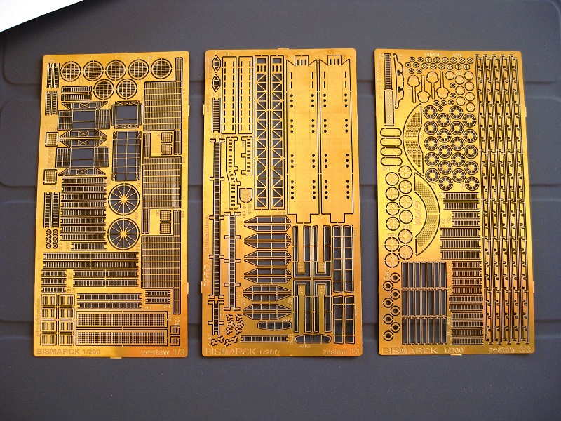
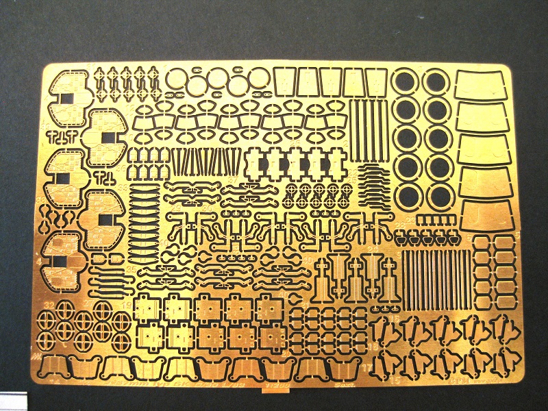
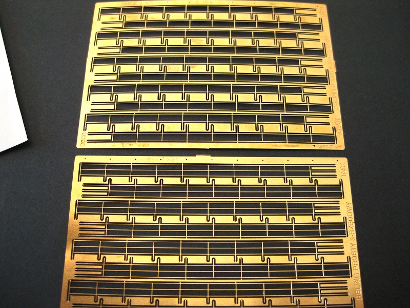
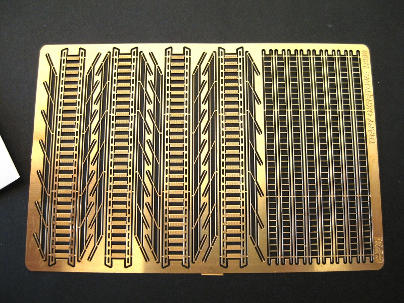
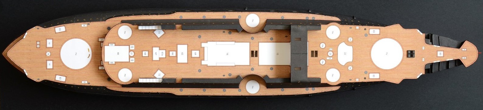
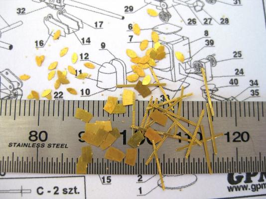
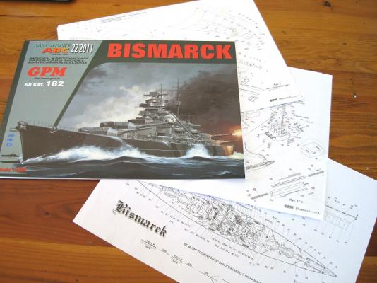
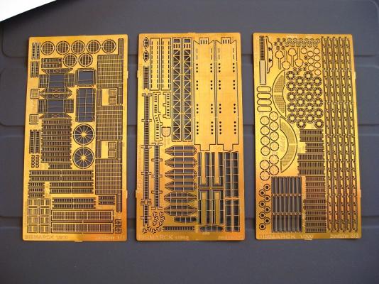
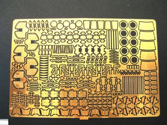
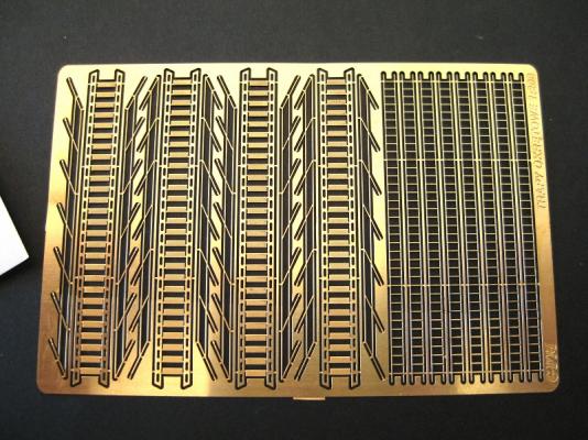
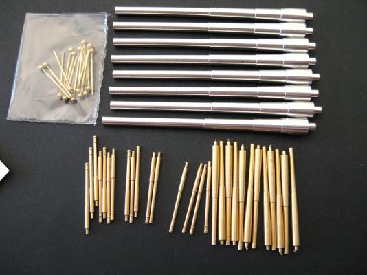
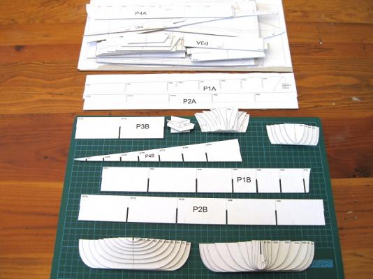
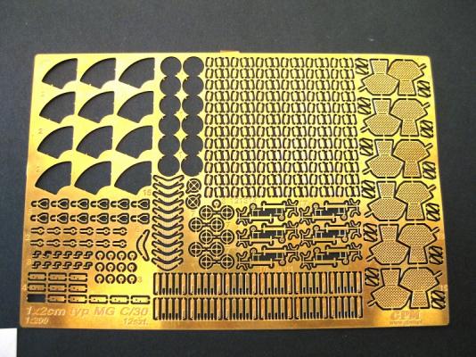
Hi, Welcome to the restart of my Bismarck card model build log An explanation of why I decided to redo my log is in order. Around the end of December 2012 I received my card kit of the Bismarck and worked on it until the middle of February 2013 and in that time I did the lower hull ribs, the funnel main structure and partially built the spotlights. The minimal log from that time was lost in the crash and I reposted a couple of pics to get going again in MSW 2.0 The build fell by the wayside due to space and time constraints and as time wore on I became less happy with the work I had done and after seeing various logs of the Trumpeter Bismarck I decided I wanted to do that version of the Bismarck with the Pontos accessary pack down the track at some stage. Lately though I decided I still wanted to do a card model and started looking again for a suitable replacement, thinking I would get something different around March. Well after some serious thought I decided to continue with the card GPM Bismarck and will order another so I can redo some of what I have done already and essentially get 2 bites of the cherry for each element Okay, on with the build log. There is nothing new to show at the moment that hasn’t been seen either MSW 1.0 or 2.0. I ordered the kit from GPM (http://gpm.pl/en ) and shortly afterwards some of GPMs own 1mm and 2mm card stock since (IMHO) the whole, which card stock to use and weights etc is very confusing. Experienced card modellers will have a list of usual stuff that works for them but starting out I thought it would be easier to use what the manufacturer stocks. I also ordered various photo etch components which I will cover below. Lastly, I bought the Anatomy of the Ship ‘The Battleship BISMARCK’ book from Modellers Shipyard (http://www.modelshipyard.com.au/ ) here in Australia as it was on sale at the time. The kit (do you call a printed book a kit?) is an A3 size book of 20 plus pages. The inside cover is the history and specifications of the actual ship. The following pages are double sided and have about an A4’s worth of instructions, 4 pages of assembly plans showing the parts assembly and where they go and a general arrangement plan showing major assembly positions. There are around 9 thin single sided pages for all the ribs, forms underlying structures etc that need to be glued to thick card and make up the hull, structure etc. There are 16 pages of thicker paper which contains all the printed colour parts, details etc . These are used straight from the sheet and glued to underlying formers or attached to thinner card before use. The printing and colouring appear very good (although I found some components a bit dark). The overall ‘paint’ job has a degree of weathering which I think looks nicer than straight blocks of single colours. It also depicts the Baltic paint scheme (I think?) with the black and white diagonal stripes and the aerial recognition swastikas on the decks. As expected everything is in Polish but I typed all the instructions in to Google Translator and then pasted into Word, saved and printed out the English translation. On the whole it makes sense with a couple of strange bits but nothing to worry about. Any words on the plans themselves I just enter the word and then write it on the plans. The numbering can be confusing initially but once you get used to it is pretty straight forward. Each individual part has a part number which when completed into a specific item becomes an assembly with another assembly number which is shown on the arrangement plans for placement. Previously as I completed parts and assemblies I would highlight the part and assembly on the plans with a yellow highlighter to show they were done. The brass Photo-etch detail set consists of 3 sheets and is used to replace some of the finer details which would be either 2 chunky or basic if paper. The stand out items are the radar antennas and aircraft catapults. Compared to a plastic kit detail set like Pontos or MK1 there isn’t nearly as much but enough to sharpen it up. Next to each part there is a number etched in which corresponds to the part numbers on the plans it replaces. I went through and highlighted the plan numbers to show a replacement etch part is available. The 20mm cannons are replaced by this photo etch sheet which makes 12 cannons. The GPM website recommends 1 sheet for the build. The sheet also comes with a little printed piece of paper with the assembly diagram. Each gun has 20 parts to it excluding the ammo magazines which are made of 3 pieces each. The 37mm cannons are replaced with 2 photo-etch sheets with each sheet containing enough parts to build 5 twin 37mm cannon assemblies giving a total of 10. The assembly diagram shows 40 numbered parts but since there are more than one of some parts the total is 65 parts per complete cannon assembly. The website suggests 1 sheet of 2 rail hand rails and 6 sheets of 3 rail handrails for the build. 1 sheet is needed for ladders and stairs. The stairs actually have a tread pattern in them. The detail set above contains quite a lot of specific size ladders so these must be supplementary to that. I also got the gun barrel set which contains the 380mm (15”) in aluminium, the 150mm (6”) in brass, the 105mm (4”) in brass and brass 37mm. All but the smallest barrels have bore holes in the ends. Here are all the hull components glued on to thick card. The lower hull ribs in the bottom of the picture on the cutting mat, which will have been seen before, are all cut to size and fitted. Everything above P4B still needs trimming to final shape and fitting. As can be seen there is still a mass to do. The GPM website sells the Bismarck in a set with the laser cut card hull forms which replaces, I think, everything in the photo. Previously you could buy the Bismarck book by itself so since I have to purchase the set I will hold off continuing to trim the remainder until I receive laser cut forms to see. When I order the replacement Bismarck I will also get a photo-etch sheet of portholes, a sheet of photo-etch 1:200 scales figures and elastic thread for aerial wires. The figures are flat but I think the process is to build them up to shape with blobs of glue and then bend them to position. Again, apologies for going over the same old stuff but; fresh start, fresh log. Cheers Slog

- 107 replies
-
- 10
-
-
HI bcso7, Great another Bismarck to follow. Looking forward to more. Cheers Slog
-
Hi Mick, Sorry to hear about your bad news, I hope it works out for you. You Will is coming along nicely. Here's hoping you are well enough to work on it. I can't help with your unidentifiable parts but does the parts list give item 21 and F39 a name which might give some clues. I wondered if you would catch on to my comment in your Endeavour log about twin rudders Cheers Slog
-
Hi Ron, Just looking at your at the head on photo in post #89 above; you may want to double check the line of the wales where they hit the Stem. I think they should be more horizontal in stead of reaching up to a peak and then curve down and round the bow to the sides. Thats what I understand and tried to get it so on my build but like i say you might want to double check this incase I am wrong. I used balsa on my bow also and don't remember having any issues with glue the planks to it. Cheers Slog EDIT: Check page 58 of the AOTS. This shows better what I am trying to explain.