
Captain Slog
-
Posts
904 -
Joined
Content Type
Profiles
Forums
Gallery
Events
Everything posted by Captain Slog
-
Hi Jan, Almost there, yes she is named after a Saint. No need to worry about complicating it with Russian Cyrillic characters etc, as found her on a English speaking site and spelled in English . Cheers Slog
-
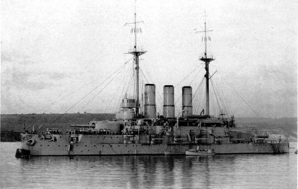
Yes Sorry Sorry again. It is named after its class of pre-dreadnought which there is only one other. Cheers Slog
-
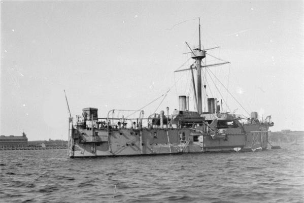
sorry Wayne. A few clues. It was built between 1903-1910 and fought at the Battle of Cape Sarych. Cheers Slog
-
 Thanks Joe, I purchased some sheets of Balsa, but been to lazy to go out to the shed to do the cutting and shaping and have neglected the build a bit for the card vehicle I am working. Thanks Grant, I agree the hull shapes of these are very nice. Looking forward to your next build David. I think you should try a commercial kit as seeing the nice work you have done with normal printer paper I can only imagine how nice you would turn out a model on thicker 'bristol' paper the commercial models come on. Hi Barry, thanks. I have sent you a PM about the rest of the GPM photo etch I have. I was tempted to get either the Pontos or MK2 set for the Bismarck as they provide so much more photo etch details than the meager GPM stuff but the cost put me off. I was heading more to the Pontos set as even the jack staff for the flags have tiny little swastika's on top of the mast. I never thought of using the wood deck though which if it worked would look nice. Cheers Slog
 -
Sorry, not Japanese Barehook is heading in the right direction...The Oslyabya is slightly too early but can see the resemblance Cheers Slog
-
Looking good there Rowan, good to see you back. Internet shopping is your friend, have a look at modellers shipyard up in Queensland Cheers Slog
-
Thanks Wayne, Unfortunately I need to rely on clues from others before I know where to start searching! Right here's my entry picked for no other reason than I love the shape of these things.
-
Okay, here it goes. Is it the sardine carrier, Jacob Pike? Cheers Slog
-
Hi John, Are you referring to Caldercrafts Admiralty varnish? I had a similar problem with a 'milky' looking finish when I used their Flat Matt Varnish on top of their Red Ochre paint thinking it would give a protective finish to the paint. I did use it on the bare wood decks of my Endeavour, although can't remember if I used 1 or 2 coats and didn't have any problems but then the decks are pretty light in colour so would't be noticeable if milky. I think the problem is after the first coat or on top of paint it can't penetrate the surface and just lies there. I can't rember but I think I touched up the Red Ochre again but can't check as it is packed away in storage. After that I use minwax wipe on poly (satin) applied with a brush as goes on nice (2 coats also) and highlights the wood. I was disappointed in the Flat Matt Varnish as it didn't change the wood one iota and can't tell it had been varnished. Cheers Slog
-
Hi Wayne, You are correct. Your turn. Cheers Slog
-
Good to see the repairs coming along. Lantern looks great. Cheers Slog
-
Thanks Kevin, I struggle to find ships to post but here it goes; I have removed some flags at the bow and stern jack staffs. Cheers Slog
-
My guess is the Blue Ribbon ship SS Sirius. Cheers Slog
-
Hi Kevin, Looking good. Are you able to still swap the main 38cm turrets around as it was 'Anton' which didn't have rangefinders (removed winter 1940/41). Your pictures show 'Casar' without the rangefinders. Cheers Slog
-
Hi Sam, Your carriages are stunning. I got so far with my Endeavour ones and put them aside until I my mind set for doing them is right. Cheers Slog
-
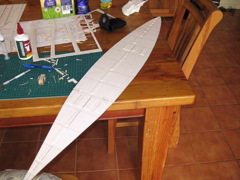
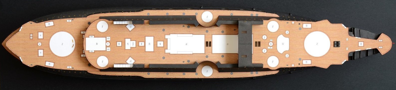
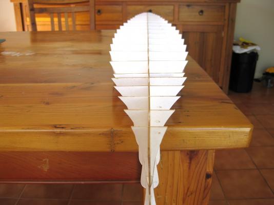
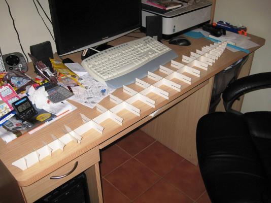
Hi All, Hi Joe, the Missouri would build into one fine ship, look forward to seeing it one day. Thanks David, it's certainly going to test my patience. Hi Sam, its definitely got some presence. The Admiral got a shock in the morning when it suddenly appeared on top of the computer desk hutch Continuing on, the middle deck which separates the upper and lower hulls comes in three parts. After careful measuring and using a 600mm steel rule to line everything up I joined the 3 parts using big squares of card cut-offs to bridge the joins. I also placed cut-offs down one side of the centre ‘Keel’ to have a firm edge to hold against when it was time to attach the hull halves. During glue up I pressed the keel against these cut-offs and stuck down more sandwiching the keel. At I couple of spots I did both sides of the keel and bulkhead. This kept the hull positioned both centrally and longitudinally for gluing. When it came time to glue up both halves I placed the horizontal deck upside down on the kitchen counter (and applied more guide scraps) and glued the lower hull down to the deck using PVA glue. The handy thing about working in the kitchen is I raided the cupboard for tins and jars of soups, sauces etc and used these to weigh down the hull. Once this was left for a hour or so I flipped it over and repeated for the upper deck. Underside of finished hull Topside of finished hull Looking down the spine of the hull it is pretty straight(ish), there a few bulkheads slightly to one side or the other but this was my fault due to rushing to get it all positioned before the glue started to go off. There is the very slightist twist to the leading edge of the bow. This is in part to the narrow cross section of the first few bulkheads. Once you go back 4 or 5 they are wider and support more on the centredeck so resist twisting. I can get rid of the twist when I come to shape the bow. Well the hull frame is more or less complete and as usual being the first time doing this lots of lessons learned and a few ideas to improve the assembly the next time I do a card hull. Still have the strips of tabs set back from the edge to do. First thing was the amount of gluing surface with the full length of the keel plus all the bulkheads meant that I was working pretty quick during glue up so the PVA didn’t start to skin up. This caused 1 or 2 little alignment issues. In future depending on the hull configuration I think I would try locating and gluing the centre keel down first then do the bulkheads. Moving on, apparently only need to fair up and then stick some card strips on to the edges then ‘skin up’ with the hull sections. This I think would be very difficult to get right, so I am going to get some balsa and bulk up the bulkheads and put in longitudinal stringers before fairing the hull. Will probably fully fill in the bow and stern with balsa so I can get the correct shapes sanded. Cheers Slog


- 107 replies
-
- 14
-

-
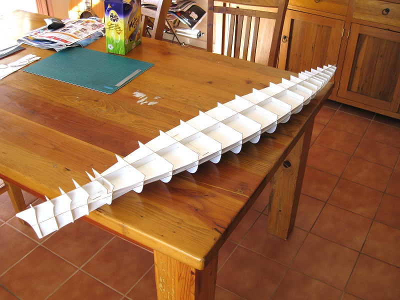
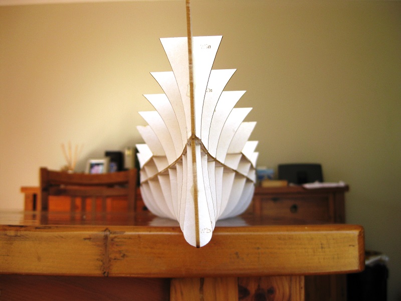
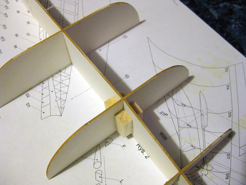
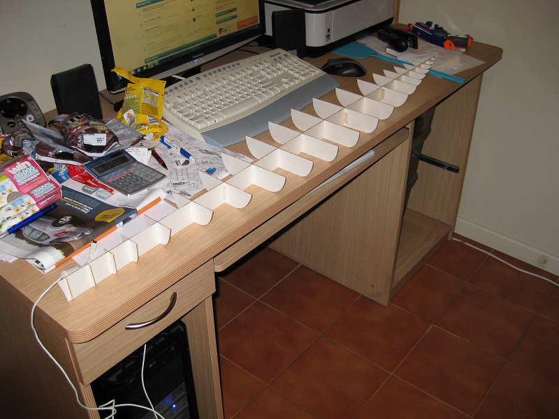
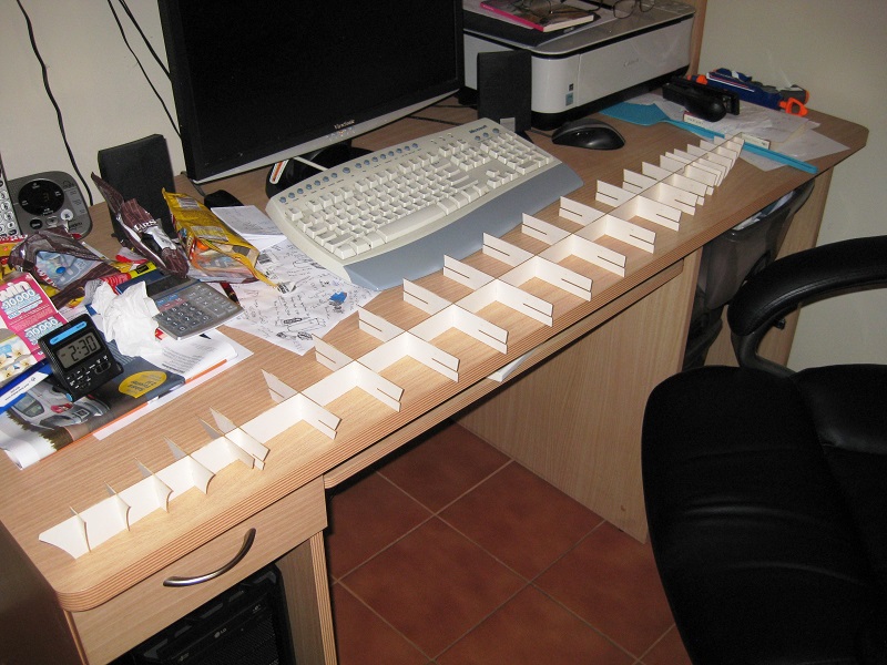
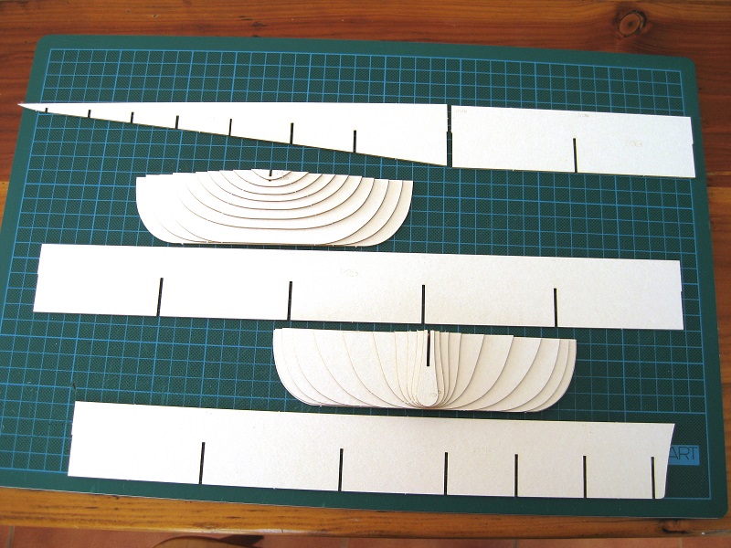
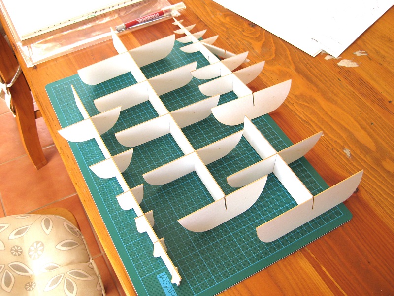
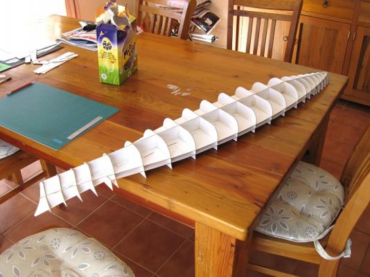
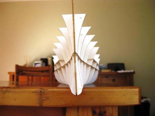
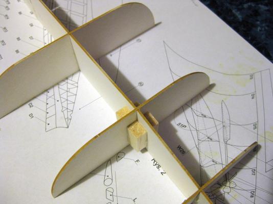
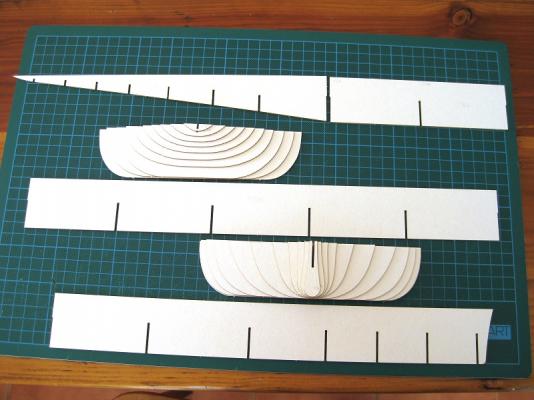
Hi Grant, yeah the forms are so much quicker and easier, not to mention cleaner! The longitudinal “keel” comes in 4 lengths, which I glued in all the bulkheads too, leaving off the ones covering the joints. I wondered how to hold these whilst I slid the bulkheads down over the joint. Turns out it was relatively straightforward. I use ordinary woodworkers PVA so just ran a bead down the join and then pressed the butts together for a few seconds and smoothing the sides with my fingers to ensure the edges were flush. After leaving the joint alone for 15 – 20 minutes the bond was strong enough to glue up and slide the bulkhead down into place. To strengthen the butt joint I glued some scrap balsa wood into the 4 corners. The lower hull ribs all glued into place and finished. The photo gives an idea of length. Next up is the upper hull which is a little more complicated as it has an intermediate deck and differing widths to account for the armoured belt of the hull. Here are the upper intermediate decks that slot horizontally into the upper bulkheads. These also have tabs to glue on, set back from the edge so the upper skins are recessed at the armour belt. The upper hull ‘keel’ and bulkheads all glued into place. All of the upper hull components slotted together straight off with no tweeking. Overall length according to the cover of the book is 1250mm (shade over 49”) Cheers Slog


-
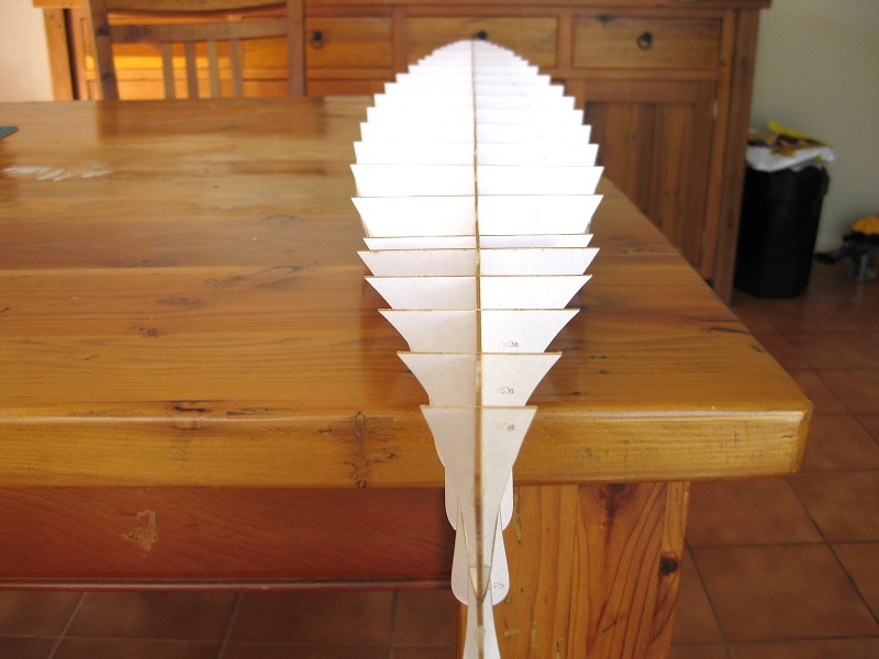
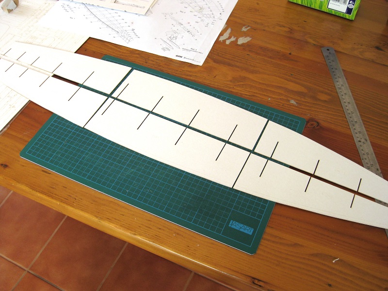
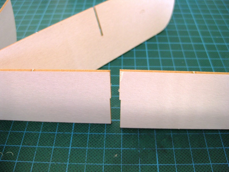
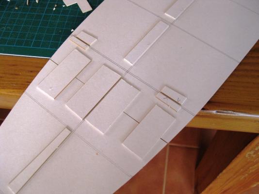
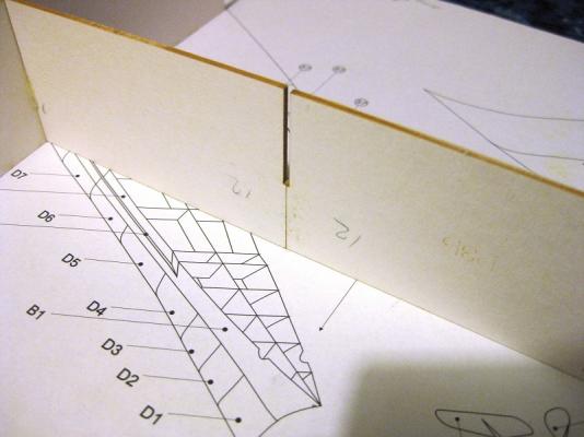
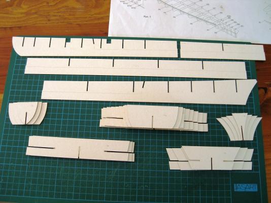
Hi Sam, having very little modelling past experience I had no idea that PE even existed until only a few years ago and am continually amazed by what is available now. It’s awesome stuff and certainly sharpens up models. Hi Bob, I’ve included a link in my signature to my card artillery tractor (Mazur D-350) log. If you want to see some incredible card detail, check out the Halinski Sherman firefly (by romanmodel) with a fully detailed interior etc. To give you an idea of detail each track link of the Mazur has 7 parts and need 81 links per side. The Halinski firefly has 27 parts per link alone! I will post something in the thread you mentioned once I progress a bit more. Have only done a couple of trial track links to see how they go together so far. Hi Tim, thanks for dropping by and the likes! Hi Barry, that’s fantastic news. I hope you will start a build log so we can progress and learn along together as I won’t be much further on than you by the time your package full of goodies arrives. Let me know when it arrives and I will PM you a translation of the instructions from Polish to English. There is only a page and a half of A4 instructions but gives some info in the steps. There are a few funny bits where it didn’t translate very well but you’ll get the idea. The majority of the build is following the schematics. Did you manage to repair your Mississippi? Did I mention how much I love the laser cut forms? What initially took a few hours to glue the templates to card, cut out; trim to shape and fit to each now took 15 minutes to pop out of sheets and push fit. From the 4 longitudinal sections and 21 ribs of the lower hull only 1 rib needs to be fitted. These are just trial fitted, I will go through and glue them into place next. In my opinion there is a design flaw as shown in the picture below. To join two longitudinal sections the joint has been located at a transverse rib/bulkhead. I think it would have been far better to move the joint off of the bulkhead so a piece of scrap could have been glued across the both sides, bridging and strengthening the joint. Small point as once the horizontal intermediate deck is fitted it won’t move but still very flexible and weak until that is done. Cheers Slog


-
I remember this beautiful build from MSW 1.0, good to see it back. Cheers Slog
-
Hi Steve, Excellent build so far. I like the interior colour chosen, goes well with the natural exterior. Cheers Slog
- 625 replies
-
- 1
-
-
- bounty launch
- model shipways
- (and 1 more)
-
Hi Steve, Your launch is looking fantastic! Whats a Fit-Pack? I am guessing it contains the syringes you were after? Did you get grief buying syringes. I vaguely remember wanting syringes a while ago to try something (Some of the Russian builders were using them, which I forget now) and ended up not bothering as expected a heap of hassle from the chemist. Cheers Slog
- 625 replies
-
- 1
-
-
- bounty launch
- model shipways
- (and 1 more)
-
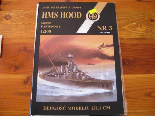
Hi Steve, I like your thinking But think I might go HMS Lion and SMS Seydlitz for The Battle of Dogger Bank and Jutland recreation I doubt I will live long enough to do all these. That’s the beauty of card models, compared to wood and plastic kits they are so much cheaper so can build up a stash pretty quickly. Hi Chris, thanks for the additional info that clears up my confusion. I really want to do the later release as the detail straight from the ‘book’ is incredible. Remember Martanek’s multiple builds, one of them was the later release Hood. I will probably give the Hood shown above away free to a good home to anyone in Australia who wants to give it a go. I’ve been sitting pouring over the laser cut forms and they are so nice it’s a shame to use them! Hopefully some progress to show next weekend. Cheers Slog
-
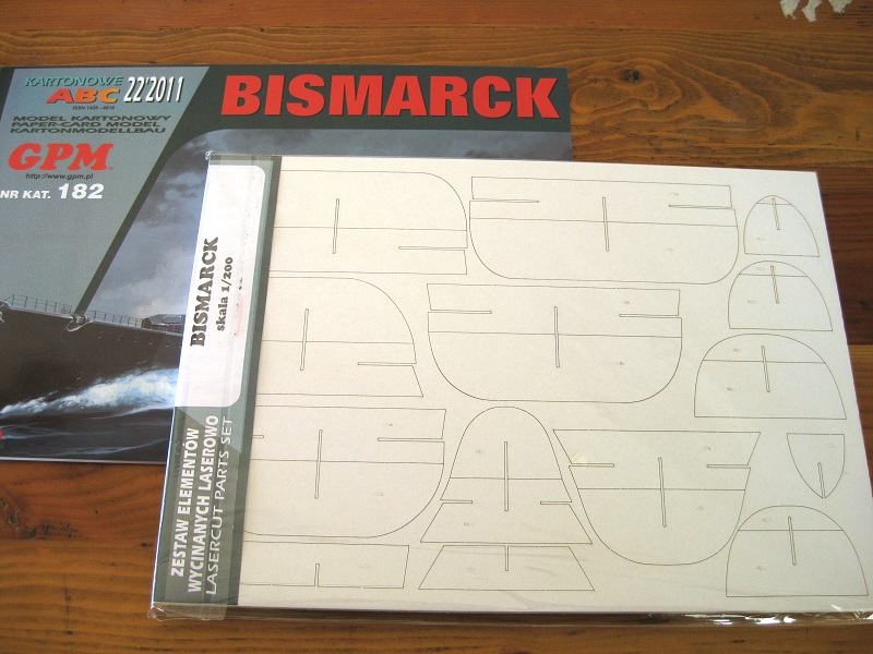
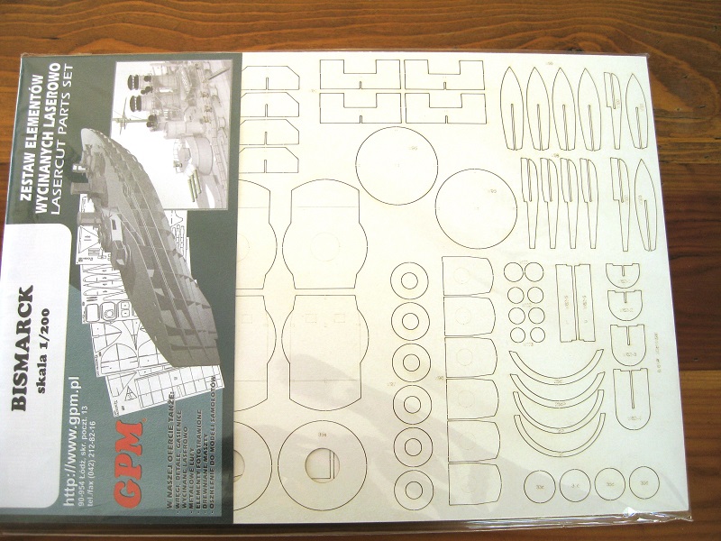
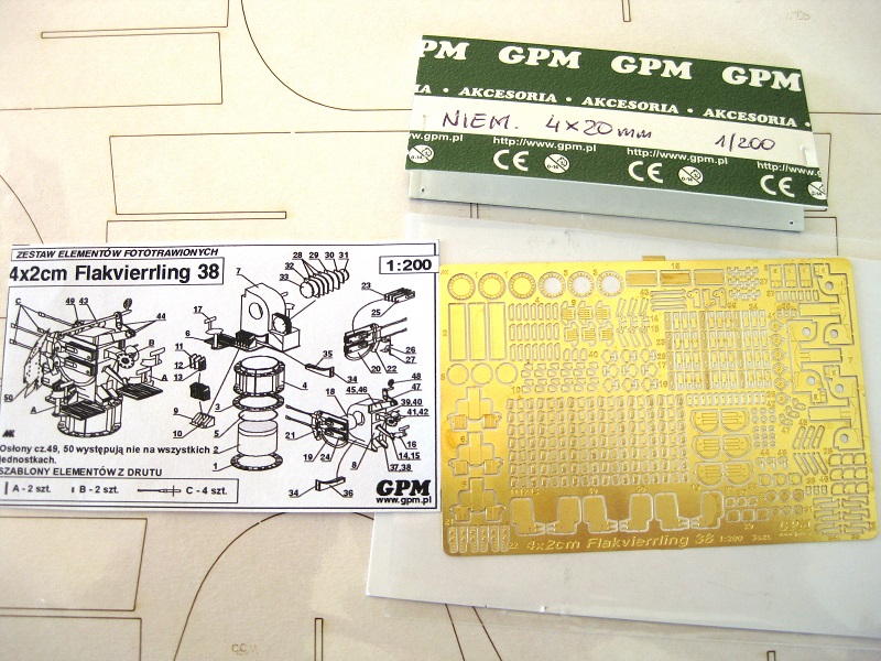
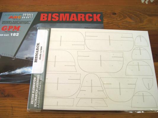
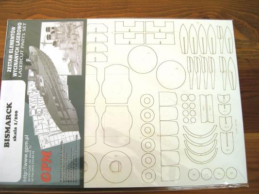
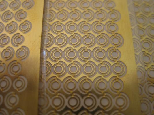
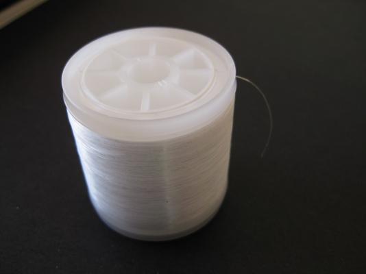
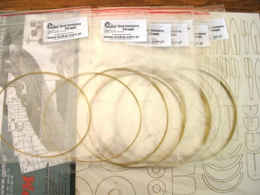
Hi Steve, surely high velocity explosive projectiles is more fun than spray Hi David and rafterrat, the Admiralty paints I mention are actually Caldercrafts own Admiralty Paint range. A very pigment heavy paint which brushes on beautifully but this is the 3rd time its messed up airbrushing. The Tamiya acrylics with their own thinners worked great. I will keep an eye out for other brands of paints you mentioned to try. Sam it was ‘Challenge’ enough just to glue the tiny parts, never mind make them move Okay I am finally able to get going again after wasting time trying to get my order through to GPM and accepted and after finally getting it sorted had a 13 day wait for the items to arrive from Poland to Australia. I got another Kit book so got doubles of most parts now. Also got the laser cut form set. It comes as 9 sheets of card with all forms pre-cut including hull skeleton, gun turrets , superstructures and more. These are incredible and for want of better words, laser sharp. I think I will now use laser cut forms for all card models if they are available. Since I am a now a glutton for punishment with photo etch I also got the quad 20mm cannons. The sheet is enough to make 3 cannons although only need 2 for the Bismarck. I also believe I don’t need to include the gun shields for these. I plan on punching out the portholes and replacing them and the drip lips (?) with photo etch. I ordered 3 different sizes as there appears to be different sizes on the hull and superstructure and they were only a few bucks each. I got 1.6mm, 1.8mm and 2mm sizes and each sheet contains 500 portholes. Lastly from GPM I got a pool of 0.2mm elastic thread, which is very stretchy and have seen this used for the aerial / antenna wires and also hand rails so thought I would give it a go. Again only a few bucks for 200metres of the stuff. Since I was having difficulties ordering from GPM and getting pretty peeved I went looking around for alternatives and came across another Polish company Orlik, http://www.sklep.orlik-models.pl/ and got a few bits and pieces from them. I was impressed with their service and they answered all my e-mails to them the next day and was very helpful. Whats a Bismarck without an HMS Hood to fight? I feel a bit of a fool as I actually thought I was buying the Halinski version and indeed it is Halinski’s with the AH badge and his name on the back cover but when I opened it and went through the pages I realised it was pretty basic and had rather less detail than other examples I have seen. I think this must be a very early release as after checking on-line the highly detailed Halinski’s have “Military Model” in large gold letters across the top of the front cover. Oh well, this is far down the track so when the time comes I may get the ‘proper’ Halinski version. Plenty of time for that. I also got some 10metre rolls of brass wire in 0.1mm, 0.15mm, 0.2mm, 0.2mm and 0.3mm since these will be useful for making hand holds, hoops, hand wheels etc , since the smallest local brass size I can find is 0.5mm rod. During my stay of absence I found a dedicated card forum and was mesmerised by the detail on the military vehicles and aircraft and unfortunately succumb to my weak will and got a couple of vehicles all from Orlik. First is the GPM WII M26 Dragon Wagon (1:25 scale) as it is a cool looking shape and has wheels to try and build. To try my hand at doing tracks I picked the Orlik Mazur D-350 (1:25 scale) as the other forum has a great looking example of this. I also got the laser cut forms for this. So I will probably do the vehicles when needing a break from the Bismarck. I was going to post some photos of the card vehicle books but decided against it in a ship build log. Next up will be to build the Bismarck hull using the laser cut forums. These are going to be so much quicker and accurate as opposed to my gluing and cutting out by hand the first set of forms. Cheers Slog

-
Hi Grant, Its been awhile since I last dropped by and she is looking amazing. How you've managed to keep track of the miles of rigging I don't know. Cheers slog
-
Greg, Sorry to hear about the mishap, that is heart breaking. Is it recoverable from or is damaged beyond repair? I would imagine most models would be salvageable from these types of incidents but guess the real question is if you have the heart and inclination to redo all your previous hard work. I hope you are able to continue with it as your build was a great inspiration to me but if it happened to me personally I don't think I have the mental constitution to redo. More importantly I hope your leg isn't to badly hurt. You really got the crappy end of the stick with this as might have meant having some sick leave to spend working on the model, you certainly copped both barrels with this. All the best Slog