

Dowmer
-
Posts
373 -
Joined
-
Last visited
Content Type
Profiles
Forums
Gallery
Events
Posts posted by Dowmer
-
-
Wow, really looking great Paul. Such a beautiful ship.
- mtaylor, Keith Black and Canute
-
 3
3
-
-
Nice Rob, delicate work at this scale. I really like the size and look of the chain. Where you get it? What size is it?
-
Quite the mountain of canvas piling up. Nice work Rob.
-
1 hour ago, Maurys said:
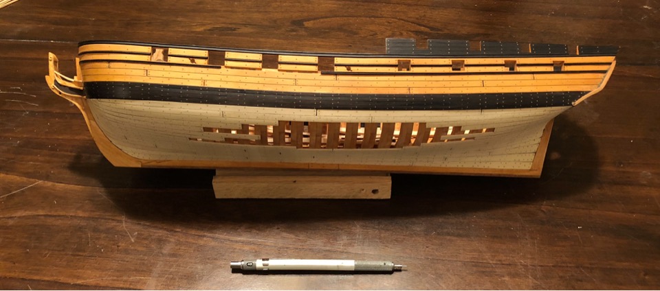
It looks fine when upside down and straight on, but from the side, I do not like the "bump" (more obvious on the second photo). It's not going to get better, so I think the lower planking needs to be replaced. I think if the garboard is re-done per the pencil line, it will be OK. A lot of work to be undone, but I am just not happy with the lay of the planks.
Maury
I agree with you Maury. As painful as it is to tear it out. If you aren’t happy with it now, you won’t be happy later. I think your new pencil line of the end of the garboard looks about right. The previous placement was too far forward.
-
-
1 hour ago, mtaylor said:
Having said that... they both pretty much look alike but with differences some major, some not so major. They both are about the same length overall but naturally the masting and rigging are vastly different. Once I get the plans sized and a build method I'll start a log. Probably end up working both ships at the same time.
Mark, if your enthusiasm for the Licorne has dwindled, why not convert your Licorne build over to the Belle Poule? Are the hulls similar enough? Masting and rigging is easily changed. Stern and taffrail is easily modified as long as the hull shape is pretty close to the same.
Just thinking from a practical point of view if it is possible at this point in the build.
-
Amazing figure head carving. Well done. The ship is looking great.
-
Rob, do you make each crinkle on the jib with a wire loop? Geeeze, I’d go blind! Nice work. 👍
-
BE,
l love the color and patina of the gun. The ones here at the Naval Academy and Navy Yard (US) are more black, but I figure it’s because someone has painted them black to preserve them. I’m not sure what they would have looked like back then, but that looks pretty good to me. 👍
- Martin W and Blue Ensign
-
2
-
1 hour ago, archjofo said:
Hello,
of course you are right.
Looks really not special.
I noticed only after your notice.
Will pay attention in the future ... 😡Johann,
You misinterpreted or mistranslated his comment. He was referring to a Tennis shot. Your work is superb.
-
3 minutes ago, EdT said:
Although Jacobs ladders are shown to the top of the royal section on the photos in which the ship has pole masts, they do not extend up to the sky masthead. The stepped mast configuration I am using has shrouds but no ratlines to the royal mast head. In both cases there is nothing to the sky masthead, so at present I do not intend to add these.
Ed, how did they get up to set the sky sails? Just curious 🤓
- dvm27, paulsutcliffe, EdT and 2 others
-
5
-
48 minutes ago, Blue Ensign said:
ps.: I have now modified the coamings following your timely advice a few posts back 😊
😁 Just trying to help LOL 😂.
Your shipbuilding skills are still way above mine. Keep up the marvelous work.
- Blue Ensign and Martin W
-
2
-
BE,
I'm glad to see you spent so much time on the fastidious chainplates. You got the look just right, and it really enhances the “look” of the ship. So many people make this an after thought as they want to get busy with other parts of the build, but it’s so noticeable that it deserves the time and patience you showed it. Well done 👍
Why use the Caldercraft PE hooks? Why not make them out of wire like Chuck did? I think they look far superior.
- Martin W and Blue Ensign
-
2
-
BE, do the channels rest on top of the planking or do they go directly onto the frames. I’ve never known quite how it was done?
nice job with the scuppers. A real pain to get the right look.
-
Rob, were the fore and main stays on the GR hemp or steel cable at this time?
-
-
B.E.
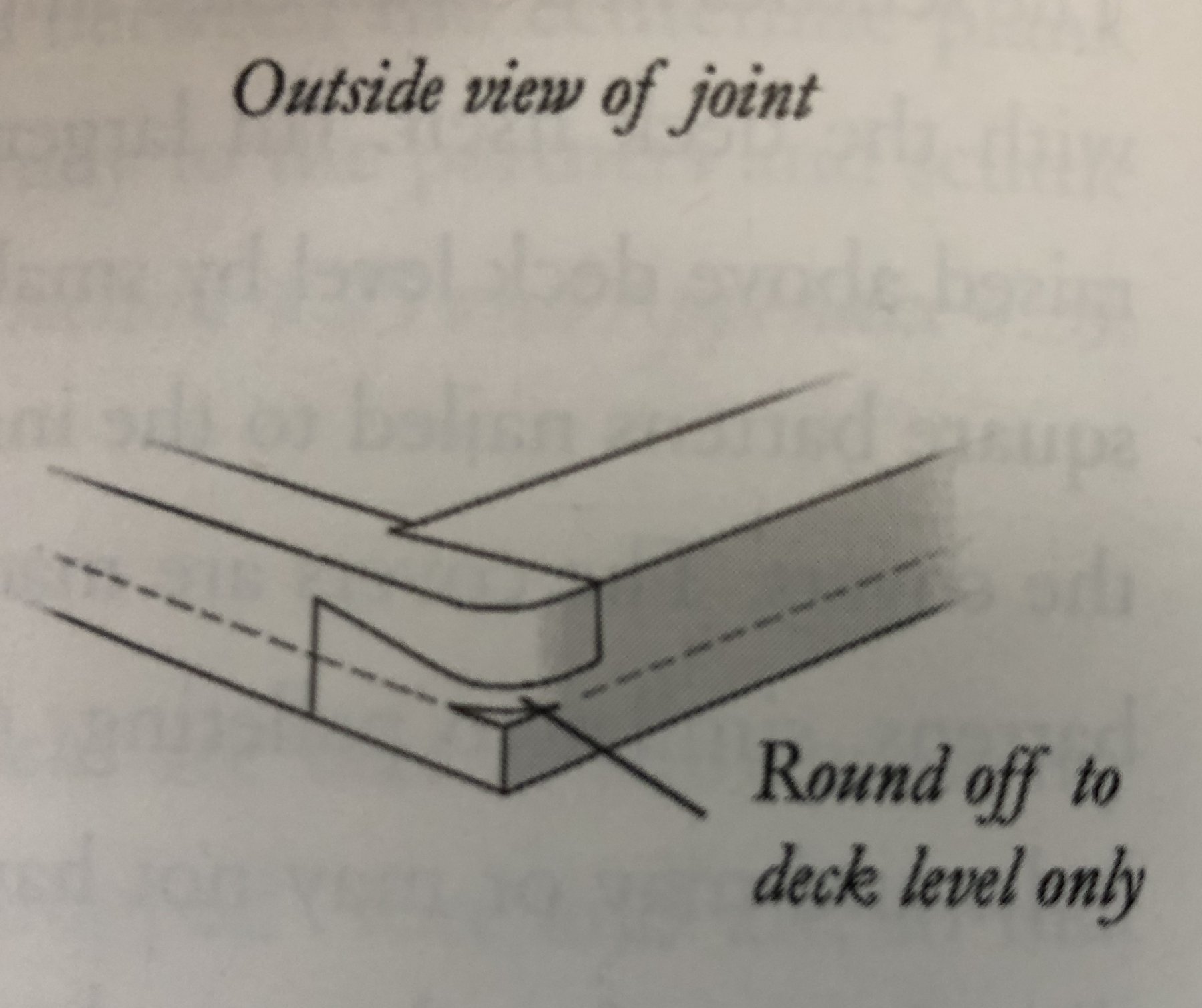
I have a question that has been nagging at me. In one of your previous pictures of your hatch coamings it shows the edge square with the top rounded off.
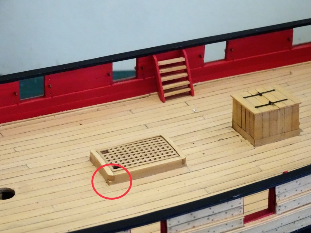
I always thought the edges were rounded down to the deck to prevent nasty ankle injuries etc. Here’s a picture of what I mean.

Are there other ways to model them?
I’m certainly no expert, and I don’t mean to be critical, but I’m always looking for accurate or contemporary ways of construction.
Thanks
-
1 hour ago, wefalck said:
Well, I would go for the left version, with the lanyard a tad darker.
I agree 👍, but it looks very nice Johann. Great work.
-
-
Ya know. Your work needs more 👍 👍 👍
-
I guess we are an OCD bunch 😁
-
Looks really good Rob.
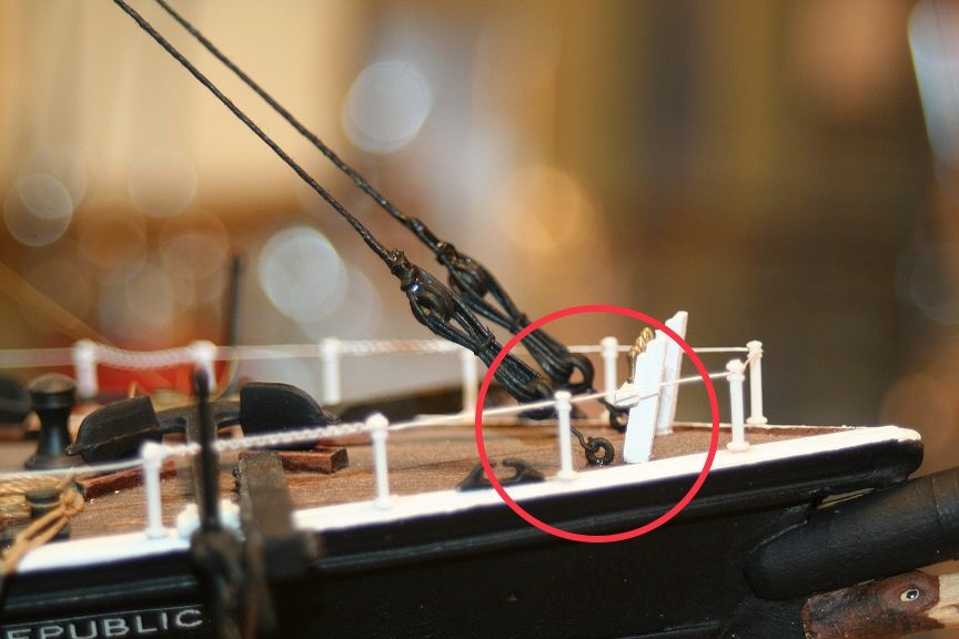
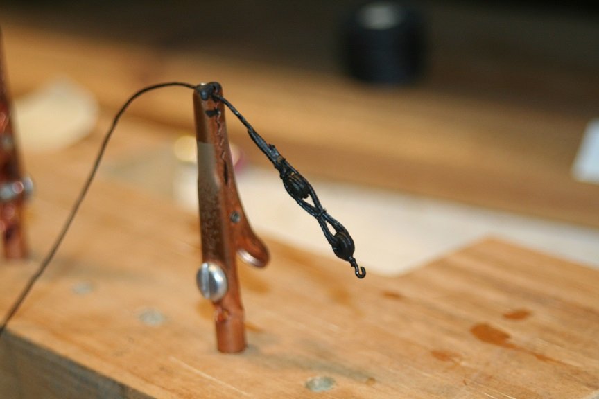
Question, is the metal hook attaching the forestay to the eye bolt on the focsl’ scale size? It appears a little small or wimpy for such a large stay.
- GrandpaPhil, mtaylor and Omega1234
-
3
-
Nice run down Ed. Thanks for the update post. Perfect with the morning coffee.
On your bowline sag with humidity, this might be heresy but I like the catenary sag. It looks more realistic than everything music string tight.
- Piet, CaptainSteve, EdT and 5 others
-
8

Great Republic 1853 by rwiederrich - FINISHED - four masted extreme clipper
in - Build logs for subjects built 1851 - 1900
Posted
Nice touch Rob. A lot of people don’t take that into consideration. Well done.