
Check out our new MSW Sponsor Innocraftsman
×

Dowmer
-
Posts
374 -
Joined
-
Last visited
Content Type
Profiles
Forums
Gallery
Events
Everything posted by Dowmer
-
 Nice run down Ed. Thanks for the update post. Perfect with the morning coffee. On your bowline sag with humidity, this might be heresy but I like the catenary sag. It looks more realistic than everything music string tight.
- 3,618 replies
-
- 8
-

-
- young america
- clipper
- (and 1 more)
-
😀 No worries Rob, I’m not really that anal. It’s just one of the things I look for since so many people get the orientation wrong (unknowingly). I understand, sometimes it is just practical at the scale you work. We all make sacrifices. The ratlin’s look very uniform and tidy BTW. Nice job. 👍
- 1,208 replies
-
- 3
-
-
- great republic
- clipper
- (and 1 more)
-
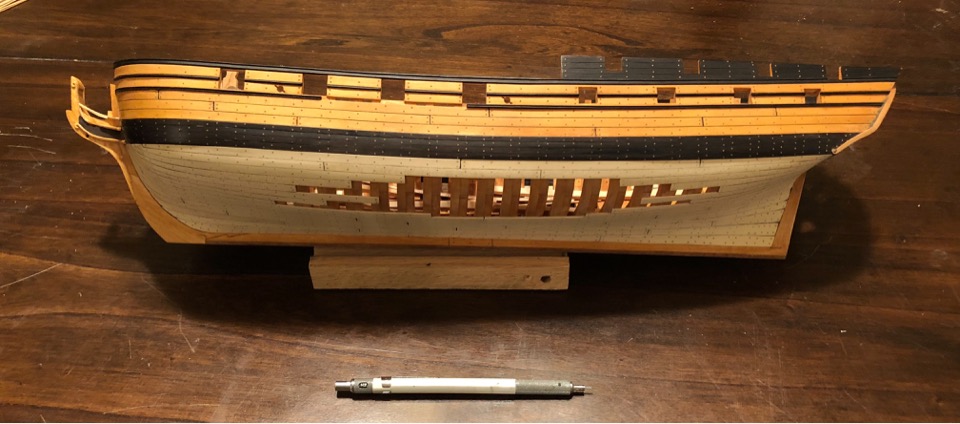
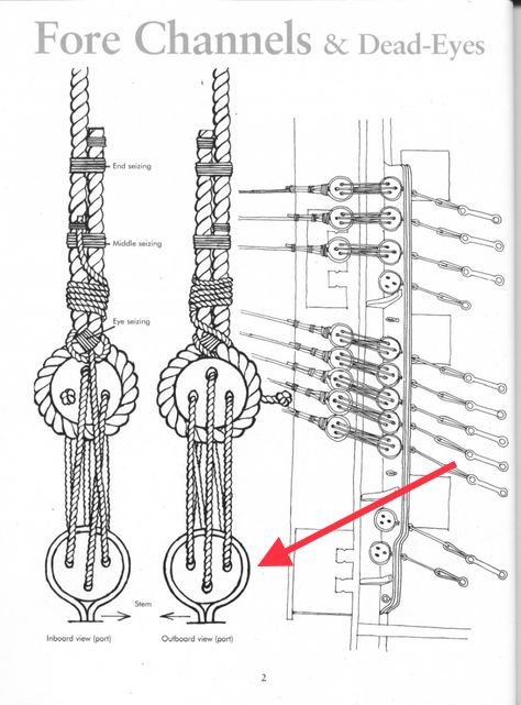
Rob, I noticed the orientation of the bottom deadeyes on the channel. Is that correct?
- 1,208 replies
-
- 1
-
-
- great republic
- clipper
- (and 1 more)
-
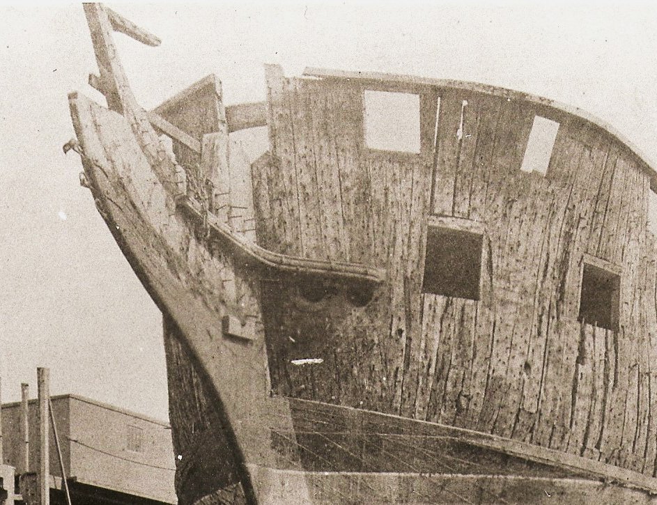
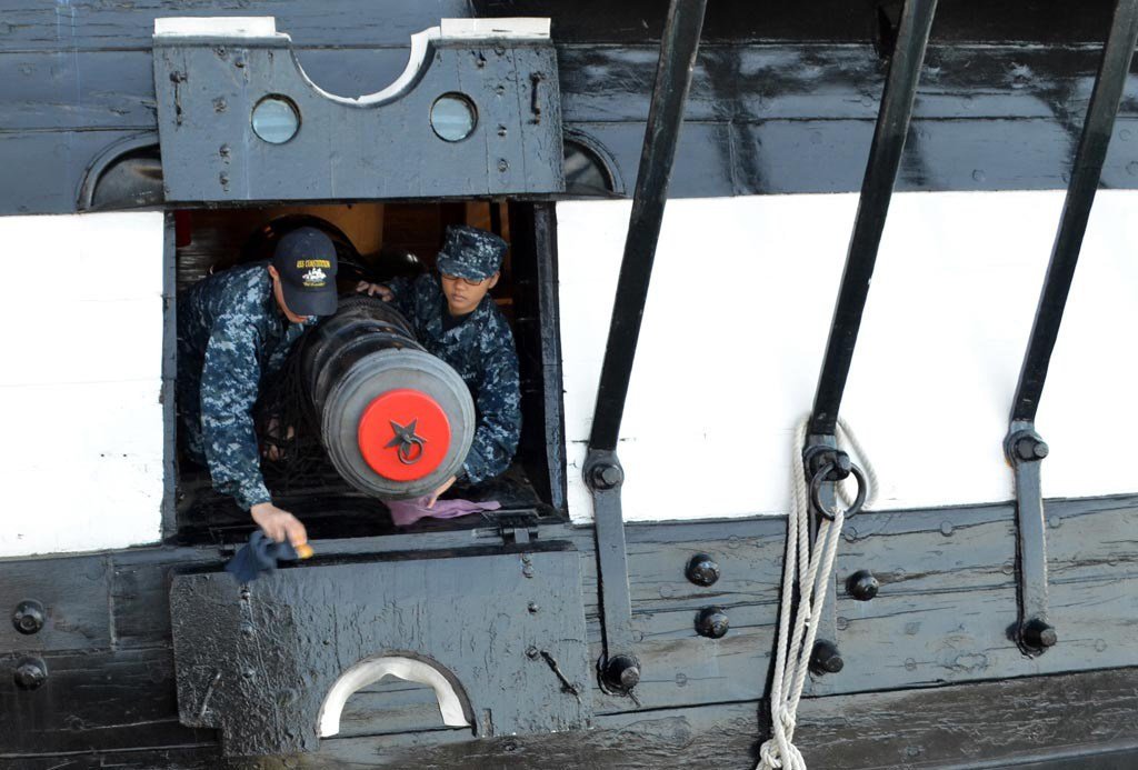
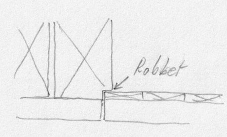
Siggi, I agree, no shortcut and these ships were built to very exacting standards, albeit with certain artistic interpretations such as the admiralty framing which isn’t full size practice. It seems that this discussion keeps stating that gunport practice was only one way. In fact, gunport practice I believe was multiple different ways....or at least two or three. The framed Bellona pictures above clearly show no port lid rabbet, but a rabbet created by the ship’s plank sides, creating a groove for the port. It also shows that the lid total port lid thickness is the thickness of the ships side planking which includes the lining. So port planking and lining = ship side thickness in this particular case. It is also very clear there is no rabbet “cut” into the frames as you suggested earlier. A bit of a different era (1797). But here is a picture of Constitution during her 1875 refit with the outer planking removed to show the frames. The forward gun ports can be seen, and no rabbet cut into the ship frames can be seen. So in this case, the rabbet was created by the ships plank like the Bellona picture above. Also, the port gun lids in photo below show that the lining was full size. Gun port Plank and lining = thickness of ship plank. No cut rabbet into the frames. Granted, the port lids were two two piece which was a later era. It’s also possible that the gun port had an extra sill lining to create the port stop like Druxey mentioned before but it isn’t clear in the picture. The point is that the port lid has no rabbet except where the two halves meet.
-
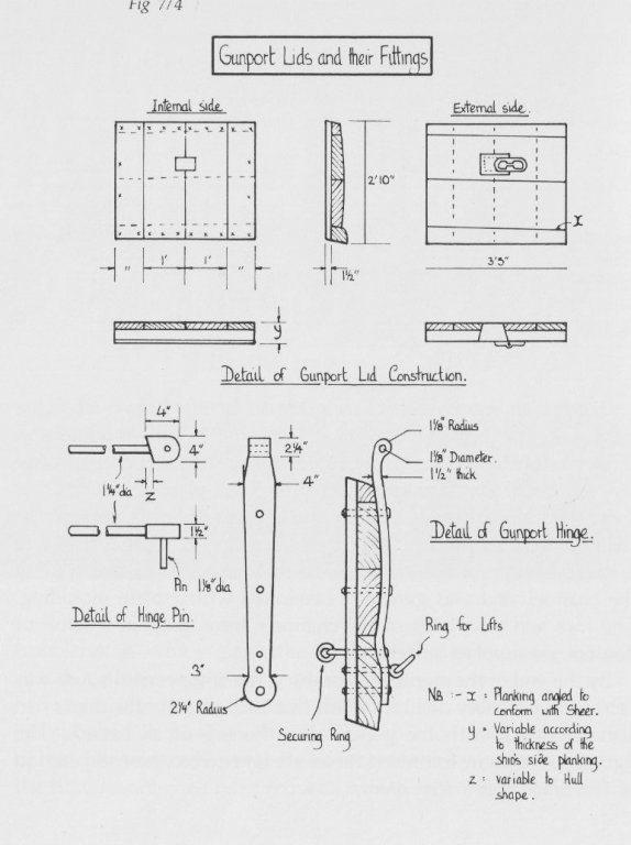
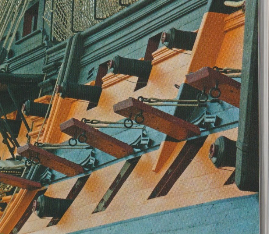
Siggi, I find this a very interesting discussion. I think Mark P and Druxey have some very fine points. One point I would like to add reference your picture below. I do not think they rabbeted into the ship frame. If you are not going to show a port lid with a rabbet then the lining and port lid plank together “equal” the thickness of the surrounding ships side plank. Goodwin shows this in the notes as Y in the drawing you posted earlier in pic below. It can also be seen in the photos of the contemporary models posted earlier and the HMS Victory you showed earlier as well. See pic below. None that I can find, show the lid rabbet “let into the ship frame” to make up for the thickness of the lining. I think you can also have a port lid with the outer lid planks the same as the thickness of the ships side planks. But when you add the inner lining, then you will need to have a rabbet on the port lid underside created by the lining “short of the stops” created, so that when the lining is added it will clear the frames. This you can see in contemporary models. I will be interested to see where Mark P’s and Druxey’s discussion resolves since they are much more informed than me. Happy Holidays
-
Sail design for 18th-century longboat?
Dowmer replied to Cathead's topic in Masting, rigging and sails
It depends on the direction of the wind. Yes, they were a general utility boat ferrying supplies, equipment and people back and forth. They were also used for exploring shallow waters and depth soundings. so the answer which I’m sure you will love is......”It depends” on the winds, current etc. -
Ditto, I’d drop the black too. No real reason to keep it IMHO.
-
BE, beautiful work and a Merry Christmas from the other side of the pond. Personal preference, I like the natural wood handles on the Elm Tree Pumps. It makes them stand out a little instead of the detail being lost if it was all black. The discharge could be red however. I figure it would need some preservation. cheers
- 574 replies
-
- 2
-
-
- cheerful
- Syren Ship Model Company
- (and 1 more)
-
Chuck, How do you know if the block stopping was served or not? I always get confused on this. Looks great by the way.
- 421 replies
-
- 2
-
-
- medway longboat
- Syren Ship Model Company
- (and 1 more)
-
Alan, One of the suggestions earlier which may resolve the insignia issue, was to print the insignia flat, but thicker than required and sand it down to the desired thickness after you glue it on.
- 125 replies
-
- 4
-
-
- 9 pound naval cannon
- 3d cannon barrel
- (and 1 more)
-
Ed, Great descriptions of the process. Question, (I apologize if you mentioned this earlier but with the large thread it would be impossible to find it) For you soldering work of the copper or brass, what flux and solder do you use? I’m assuming you don’t use “Staybrite” solder. Is it some kind of paste so you can control the quantity and location with small parts? Soldering iron or mini torch? A bit of a tutorial would be appreciated. Thanks in advance.
- 3,618 replies
-
- 3
-
-
- young america
- clipper
- (and 1 more)
-
Looks nice Rob. I like the catenary sag of the clew lines on the fore main. 👍
- 1,208 replies
-
- 4
-
-
- great republic
- clipper
- (and 1 more)
-
Alan, I think hexnut was saying to print the emblem separately, sand it down to thickness required and apply to the barrel later after it’s cleaned up.
- 125 replies
-
- 4
-
-
- 9 pound naval cannon
- 3d cannon barrel
- (and 1 more)
-
Rob, Just a thought but you might be able to achieve that billowed jib look hanging away from the stay using wire instead of rope for the sheet. So it could hold the sail out so to speak rather than in real life it would hold it down.
- 1,208 replies
-
- 3
-
-
- great republic
- clipper
- (and 1 more)
-
Alan, I agree with Druxey. The resolution is too coarse. Also, with the taper of the barrel you will get those steps in the barrel if you print it lengthwise. You might consider printing it in sections vertically. It will come out better and you can glue the sections together with a dowel down the center of the barrel to hold everything straight. Then smooth the roughness with acetone and sand. You dont need to get the barrel perfectly smooth. Remember, these cannon were crudely cast and their finish was a bit rough on the outside.
- 125 replies
-
- 3
-
-
- 9 pound naval cannon
- 3d cannon barrel
- (and 1 more)
-
Rob, Looking great. I like the billow of the sails. Question: Are you going to brace the yards over a little bit? On a full size ship with all sails drawinbg, I doubt the yards would be all crossed perfectly with all the sails drawing like that. The aft sails would blanket the fore sails somewhat. So they would be more on a Broad Reach so all the sails could draw and catch the wind. Just a suggestion, either way its looking very nice.
- 1,208 replies
-
- 2
-
-
- great republic
- clipper
- (and 1 more)
-
Seizing or perhaps “serving” was what you were thinking of. Mike, increadible job. Looks 1:1 for sure.
-
Just as a side note, I've been to many third world (developing) countries where they make furniture etc and I've seen them use what looked like shoe polish on the furniture they were polishing, touching up or staining etc. So it doesnt suprise me that it works here too. I'll have to give it a try.
-
Rob, If it was me I'd rig the shrouds while there is plenty of room and no real interference. Plus it might help with arm fatigue not straining around obstructions etc. But either way its looking great.
- 1,208 replies
-
- 2
-
-
- great republic
- clipper
- (and 1 more)
-
Tomek, Outstanding work.!!!!! Could you detail how you make the sails and what material? You have excellent craftsmanship.
-
The turns in the middle of the gammoning is called frapping and was commonplace. Heres what Steel has to say in BlueEnsign’s build Log of the Pegasus post #112 Steel makes reference to cross turns of the frapping so this is the method I have adopted. When all the turns are passed, and hove tight, they are frapped together in the middle, by as many cross turns as are passed over the bowsprit, each turn hove tight: the end of the gammoning rope is then whipt, and seized to one of the turns. The frapping increases the tension; and adds to the security acquired by the purchase.
-
Coming right along. I realize it’s a steep learning curve but you are managing very well.
-
What!! No stun’sls!!!.......😫 But they are so characteristic of the clipper..... Just kidding Rob, it’s going to look great. 😁
- 1,208 replies
-
- 3
-
-
- great republic
- clipper
- (and 1 more)