


Bitao
-
Posts
407 -
Joined
Content Type
Profiles
Forums
Gallery
Events
Posts posted by Bitao
-
-
8 hours ago, SJSoane said:
hyw, beautiful jigs. They look like a joy to use. What a pity you cannot make them for sale!
Mark
Hello. I like to develop and make my own tools. In order to make the model more accurate and efficient,. Of course, it's not for sale. Few people in the country can buy what I make for their own use. After all, I'm a model enthusiast, not a businessman.
-
-
-
-
10 hours ago, BANYAN said:
Oh come on now; you have to have a team of elves out the back doing this?
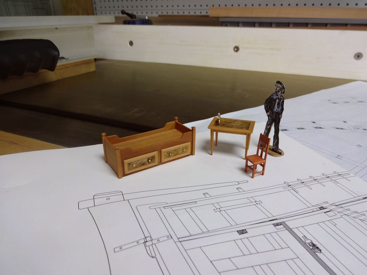
") Truely beautiful detail; you are a master craftsman - I think any cabinet maker would be proud of those furniture items, yet alone these being at scale!
Truely beautiful detail; you are a master craftsman - I think any cabinet maker would be proud of those furniture items, yet alone these being at scale!
Is that small vise / gripper you show at post #67, 7 down a purchased item? With your skills, you probably made this? It looks a very handy tool/accessory. If you made this would you please show some other shots of it?
DSC01115.JPG.62923c7e9edf6173126b42106c0c3069.jfif 151.55 kB · 3 downloads
cheers
Pat
Thank you for your appreciation. I've posted this rectangular locator separately. If you're interested, you can take a look. I designed and built them myself.
- hexnut, mtaylor and Jorge Diaz O
-
 3
3
-
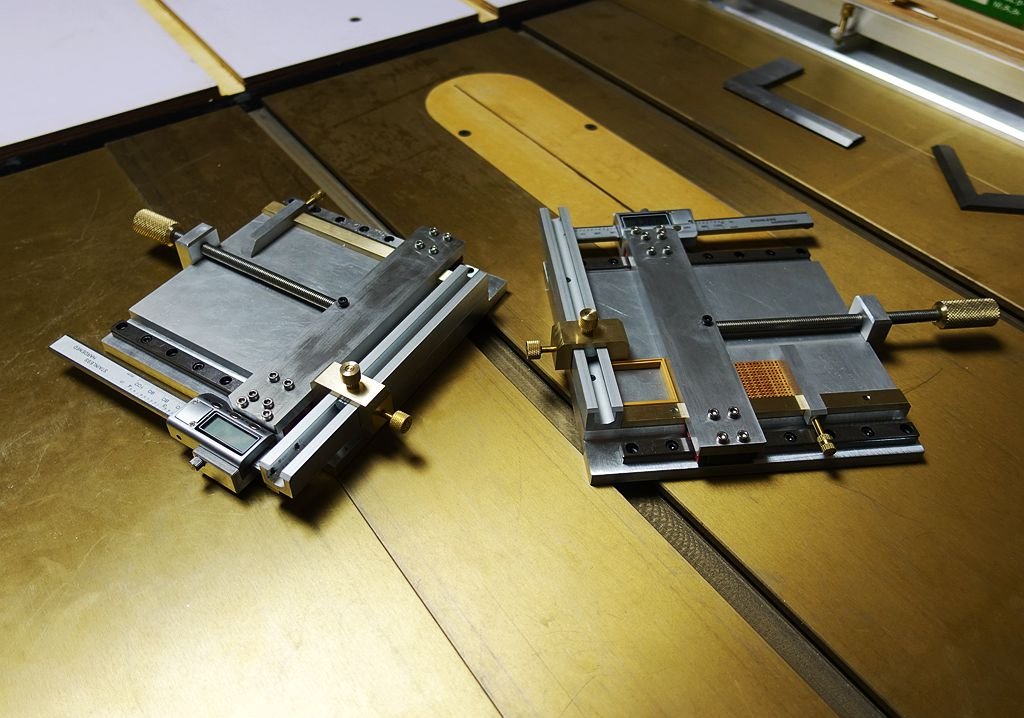
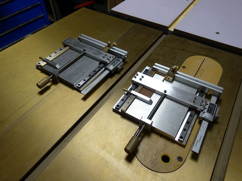
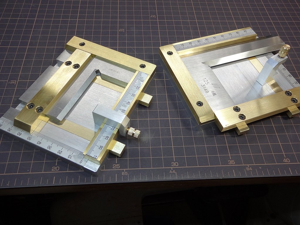
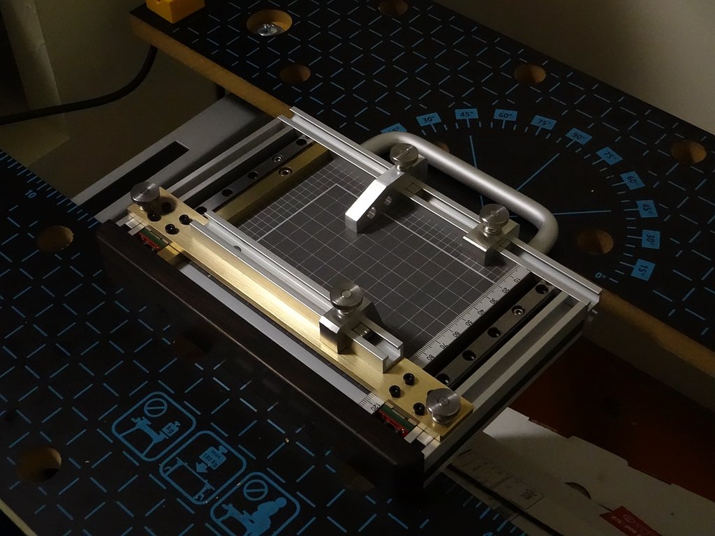
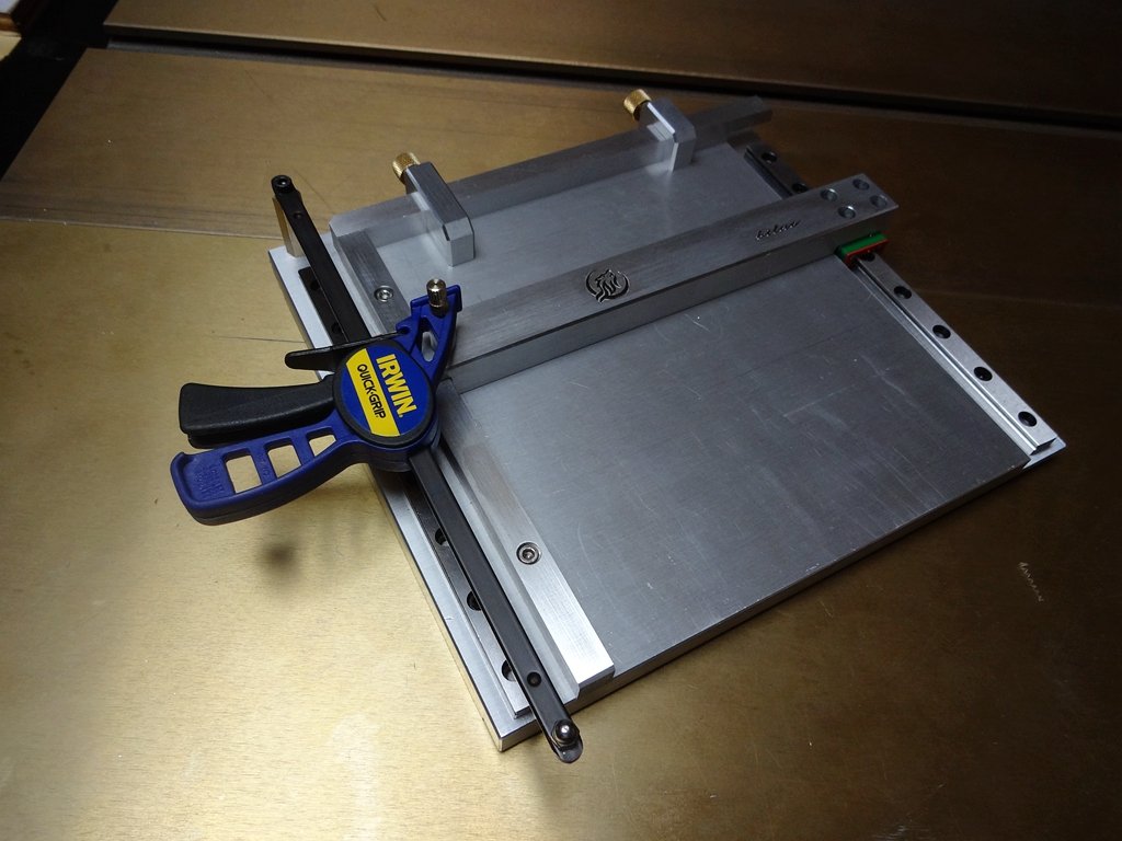
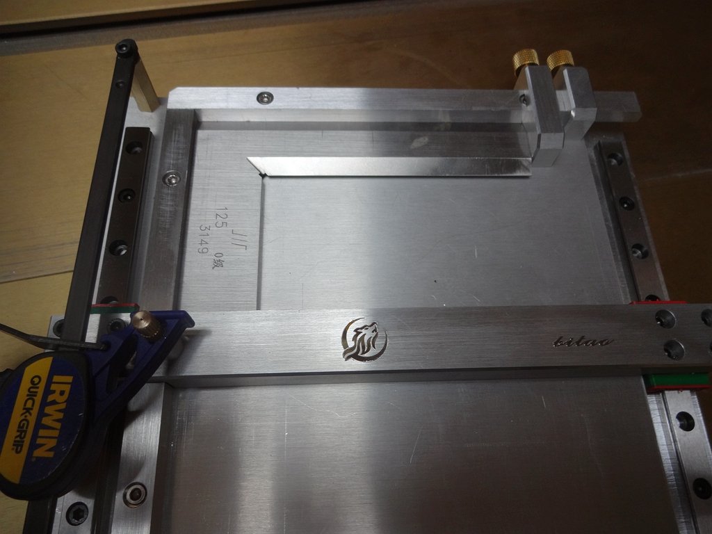
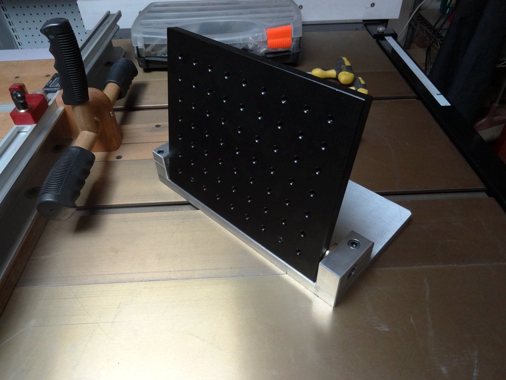
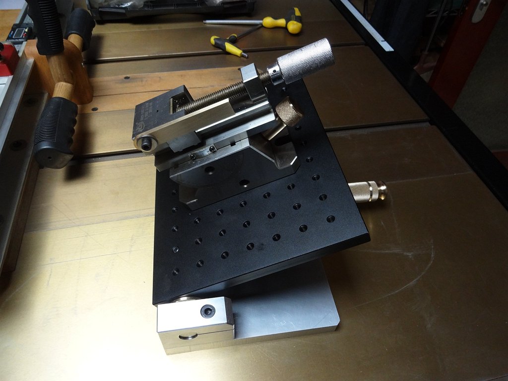
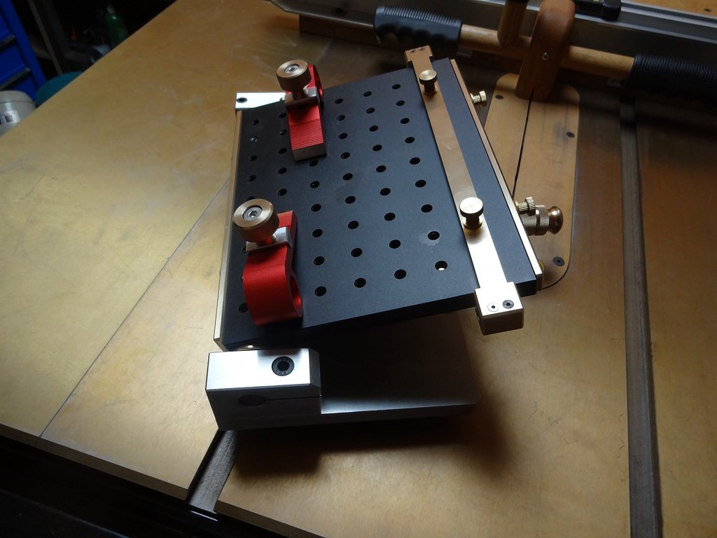
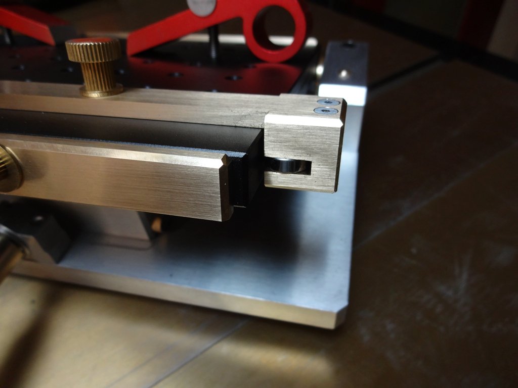
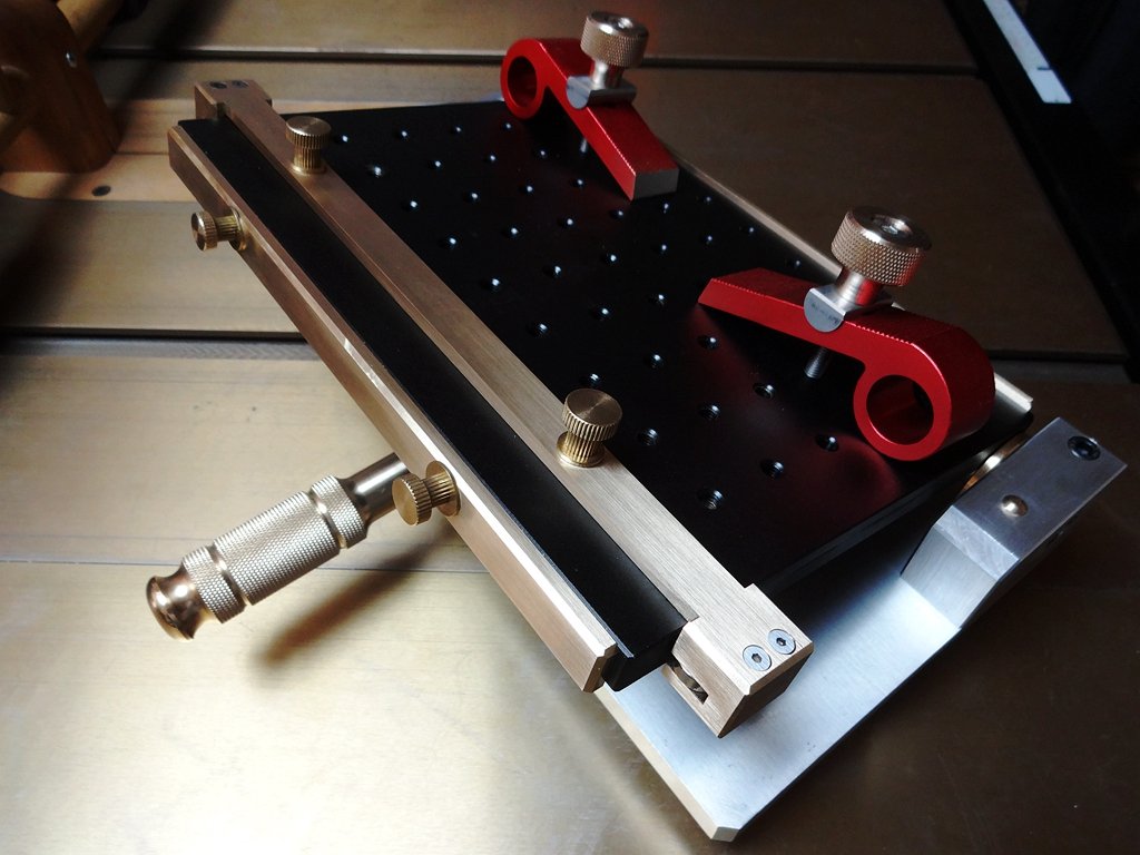
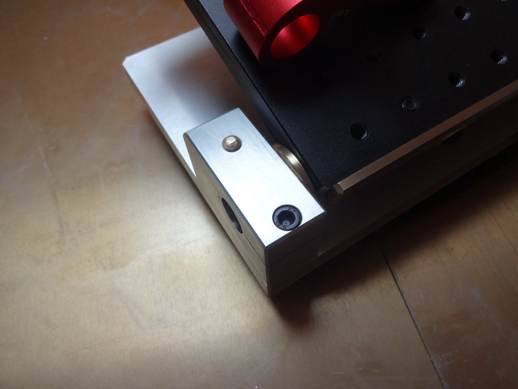
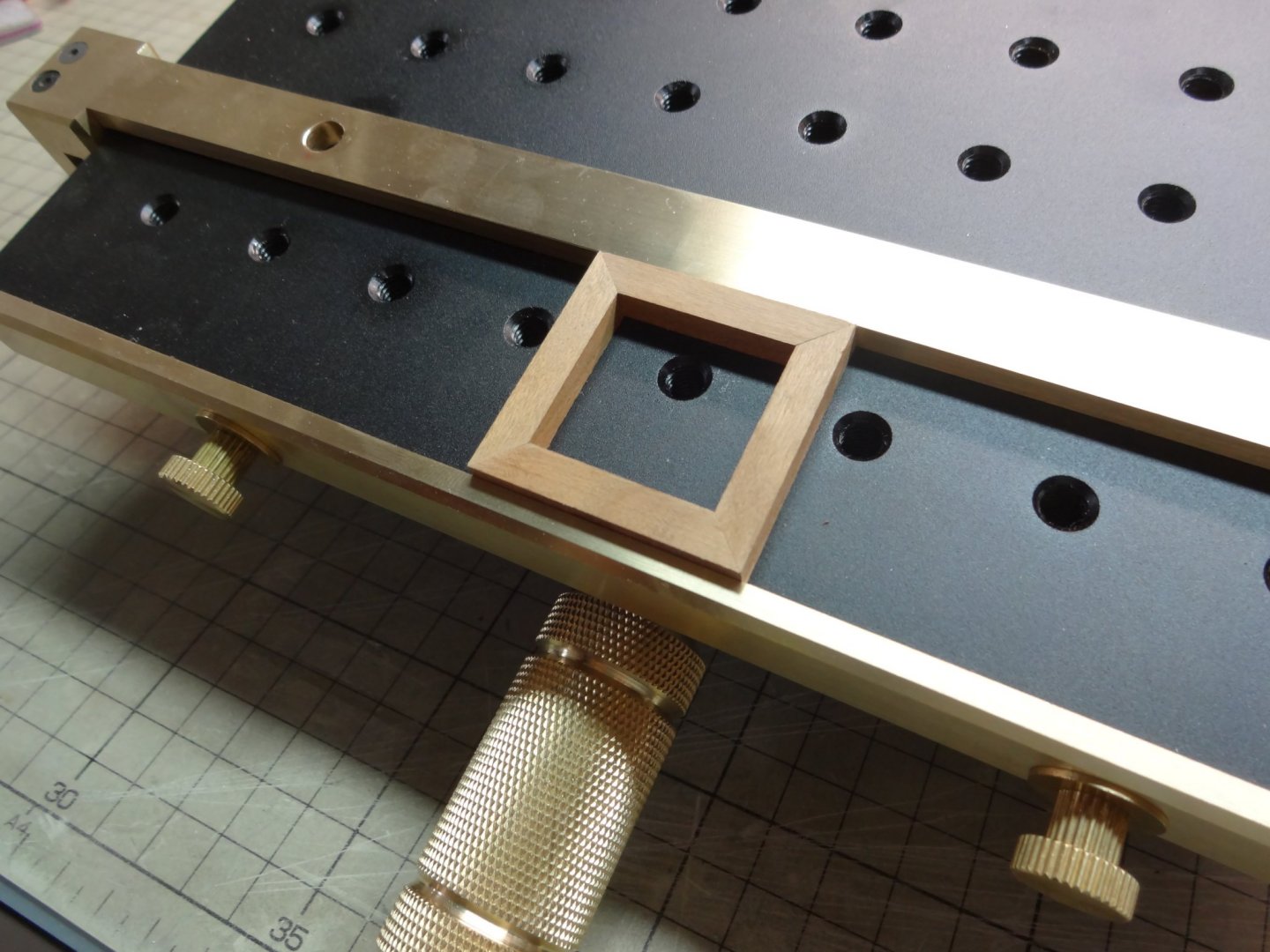
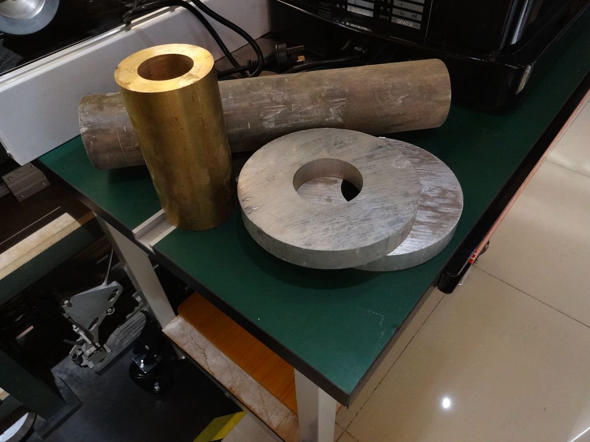
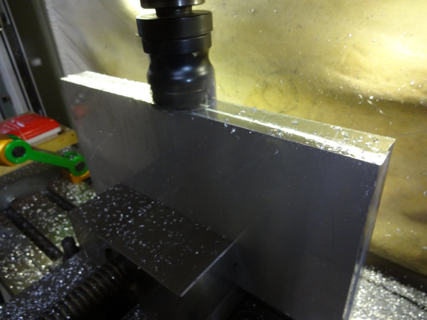
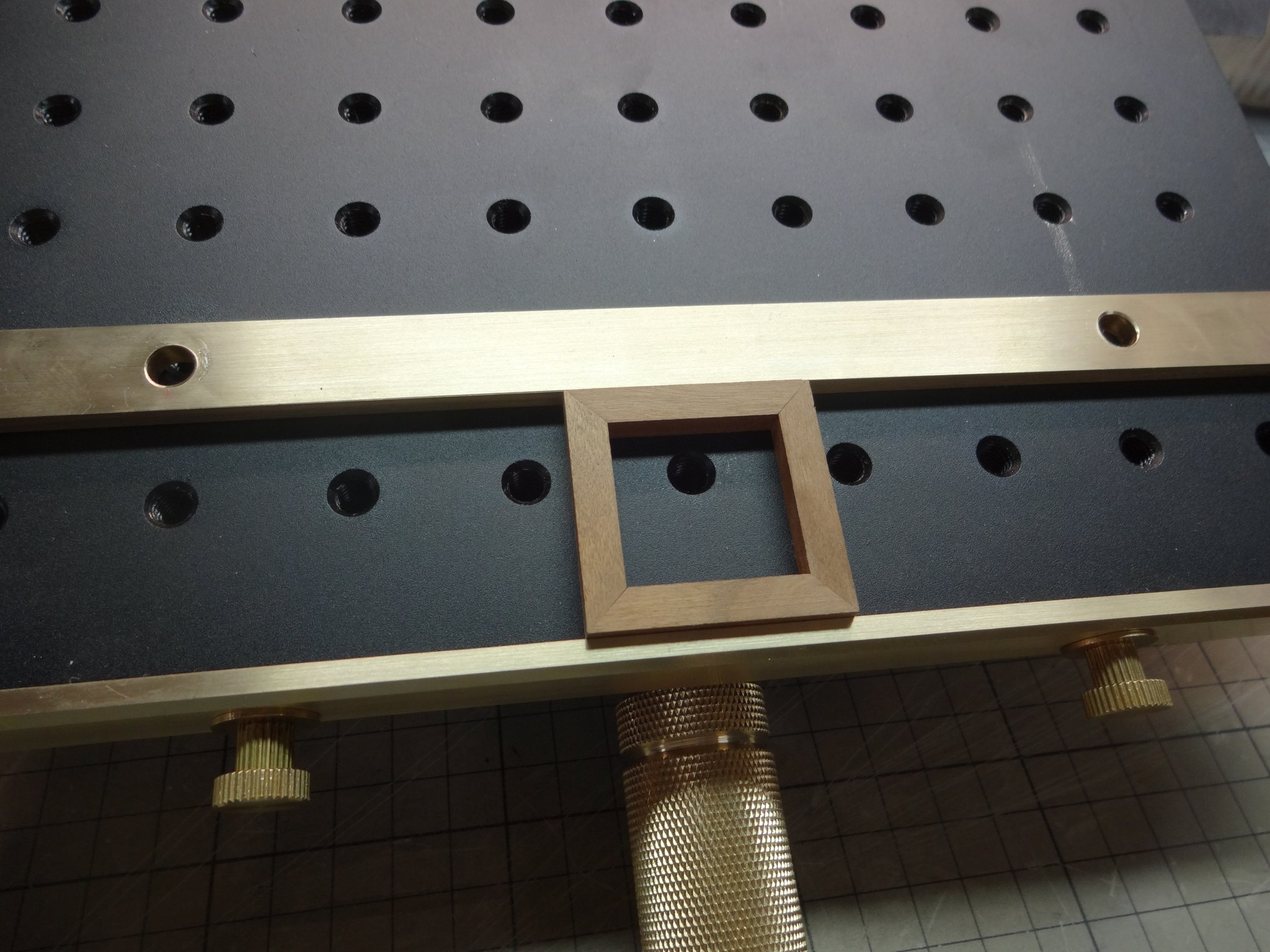
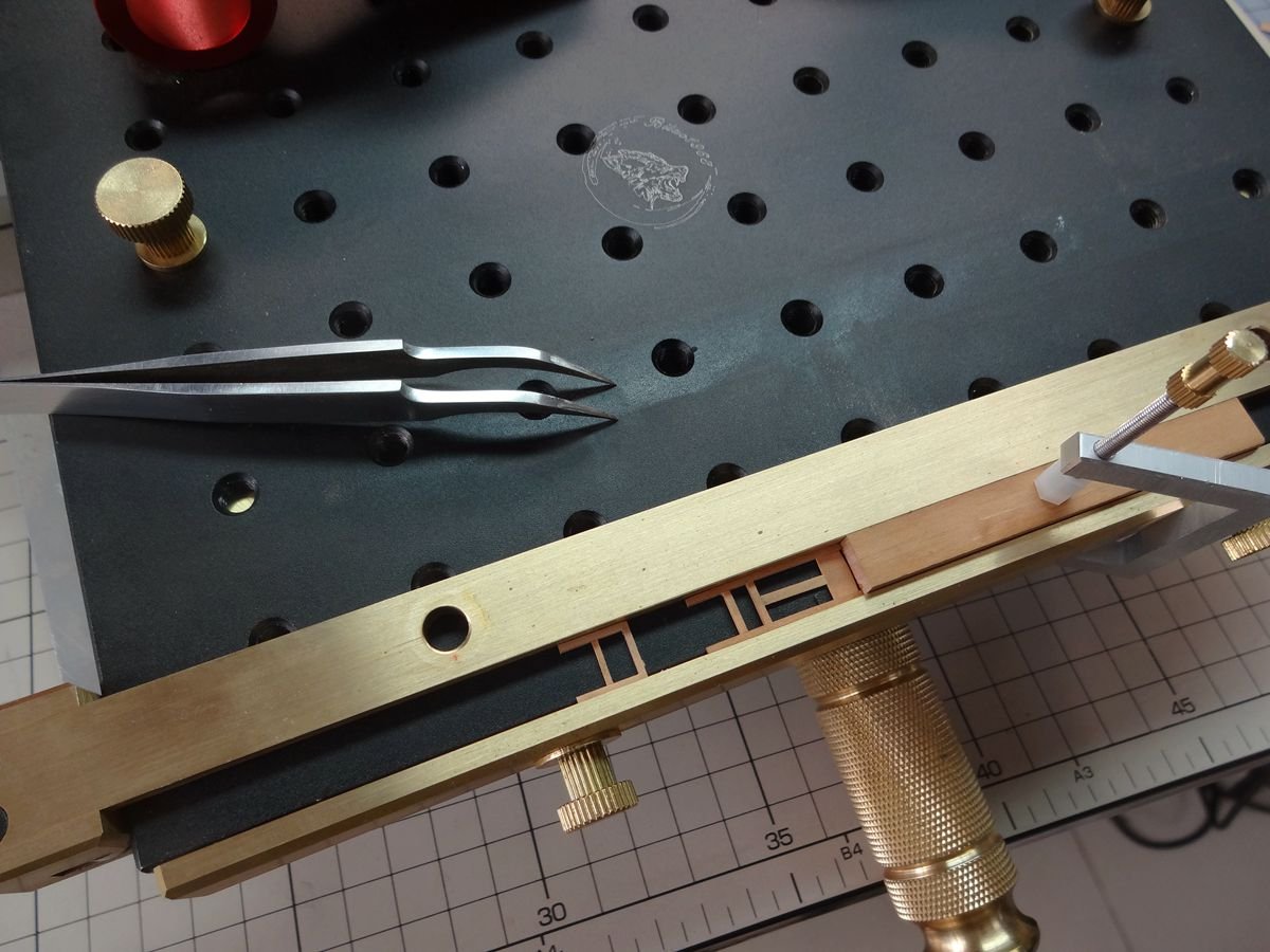
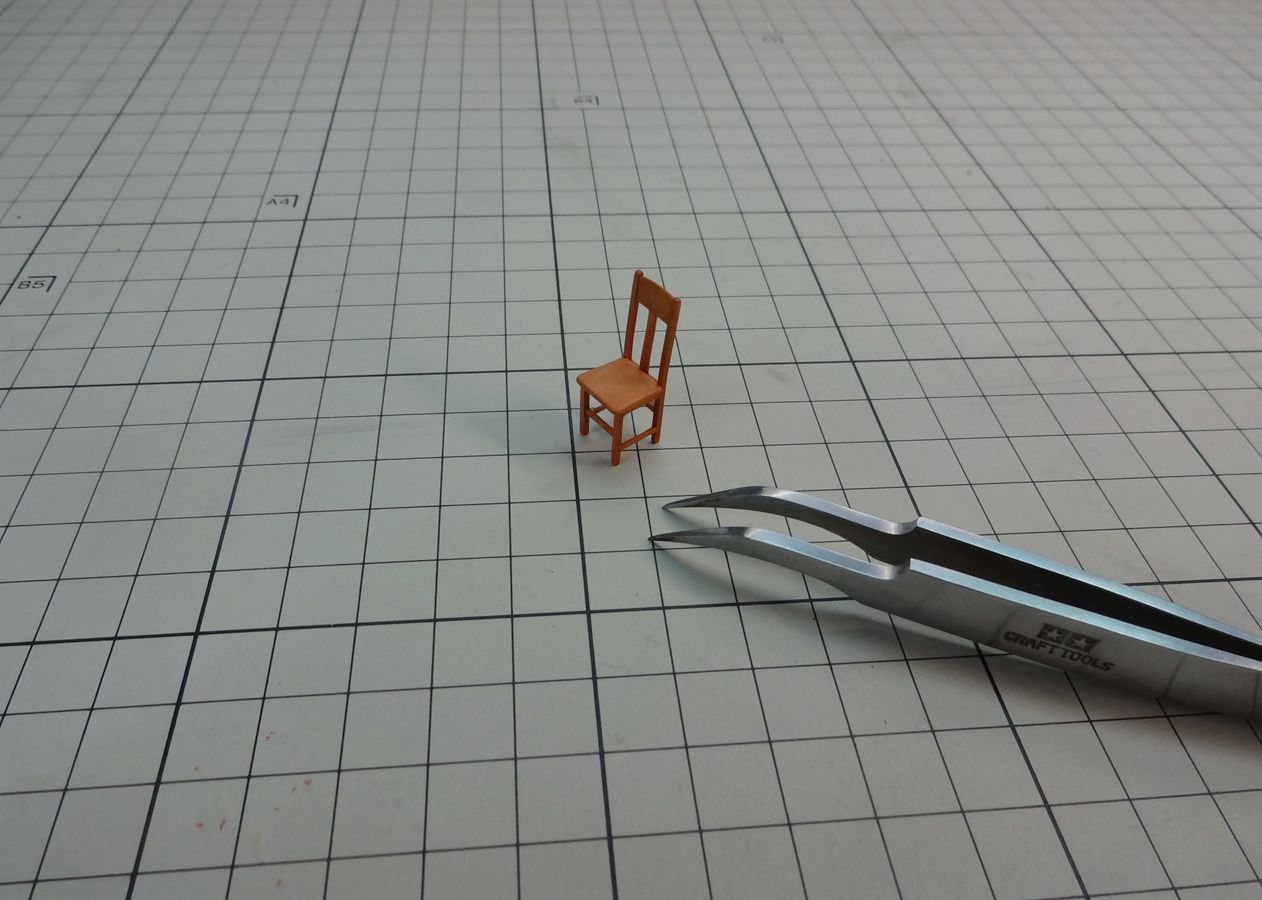
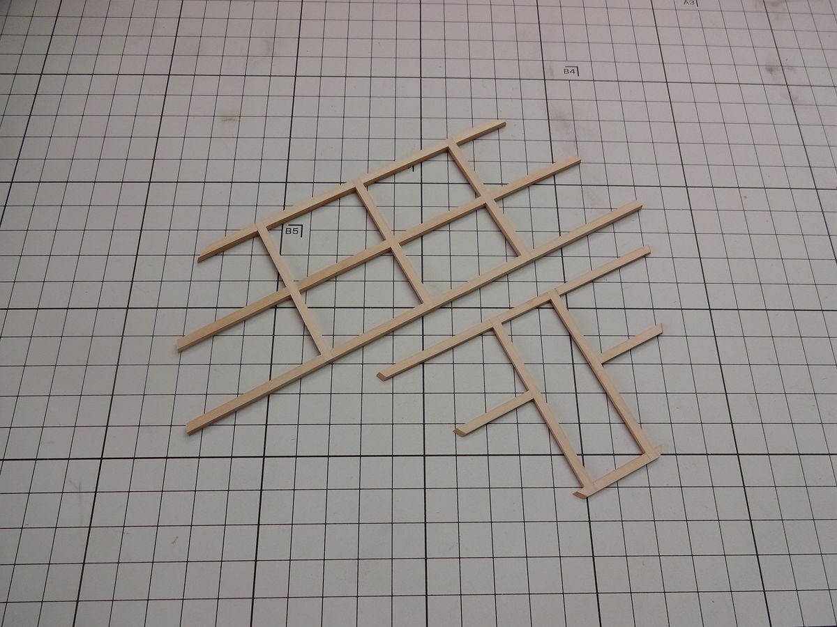
Five versions of the rectangular positioner have been designed and manufactured; the last one can be used in the plane machining of the milling machine with adjustable angles, especially the slotting of various angles of the Keel, the ribs and the crossbeam. At the same time, it can also be used as a precise positioning of rectangular assembly. The metal material can avoid the overflow of glue which makes the workpiece difficult to separate. The material is high hardness aluminum alloy (6061) and brass (H59) .

-
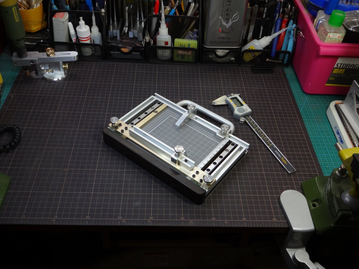
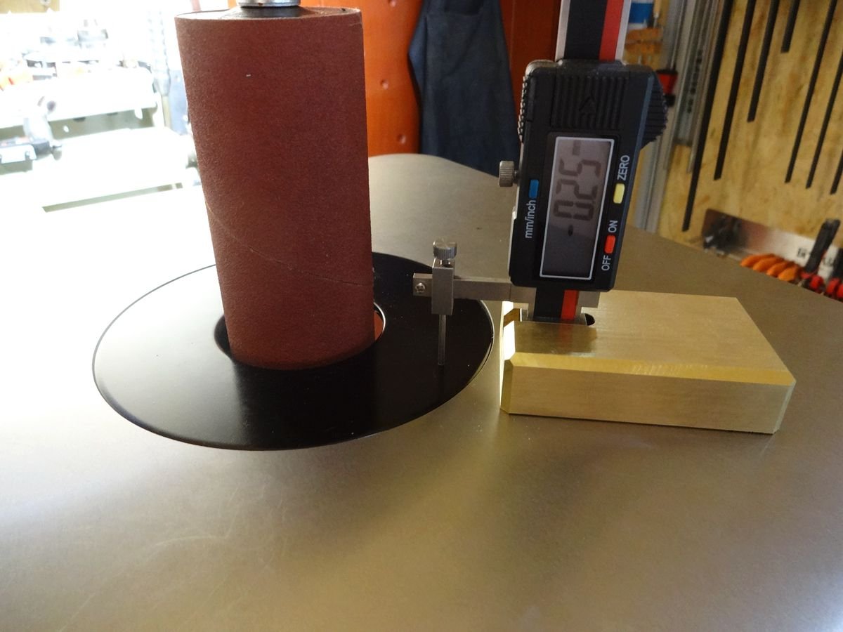
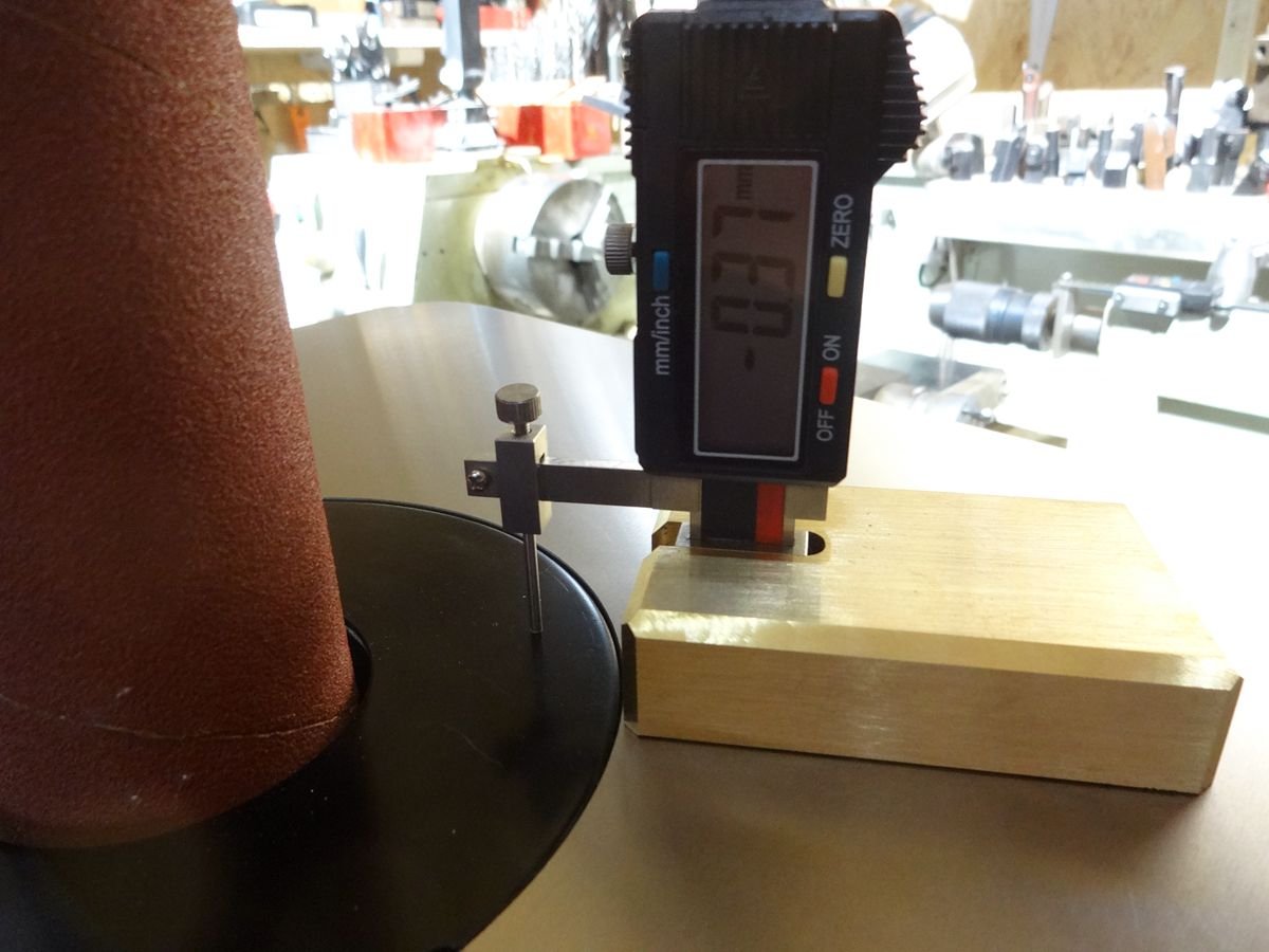
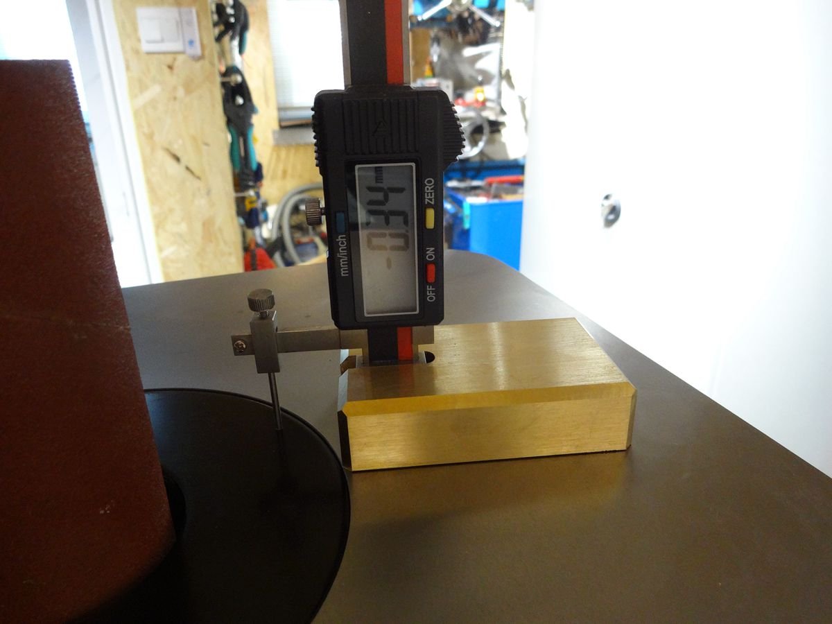
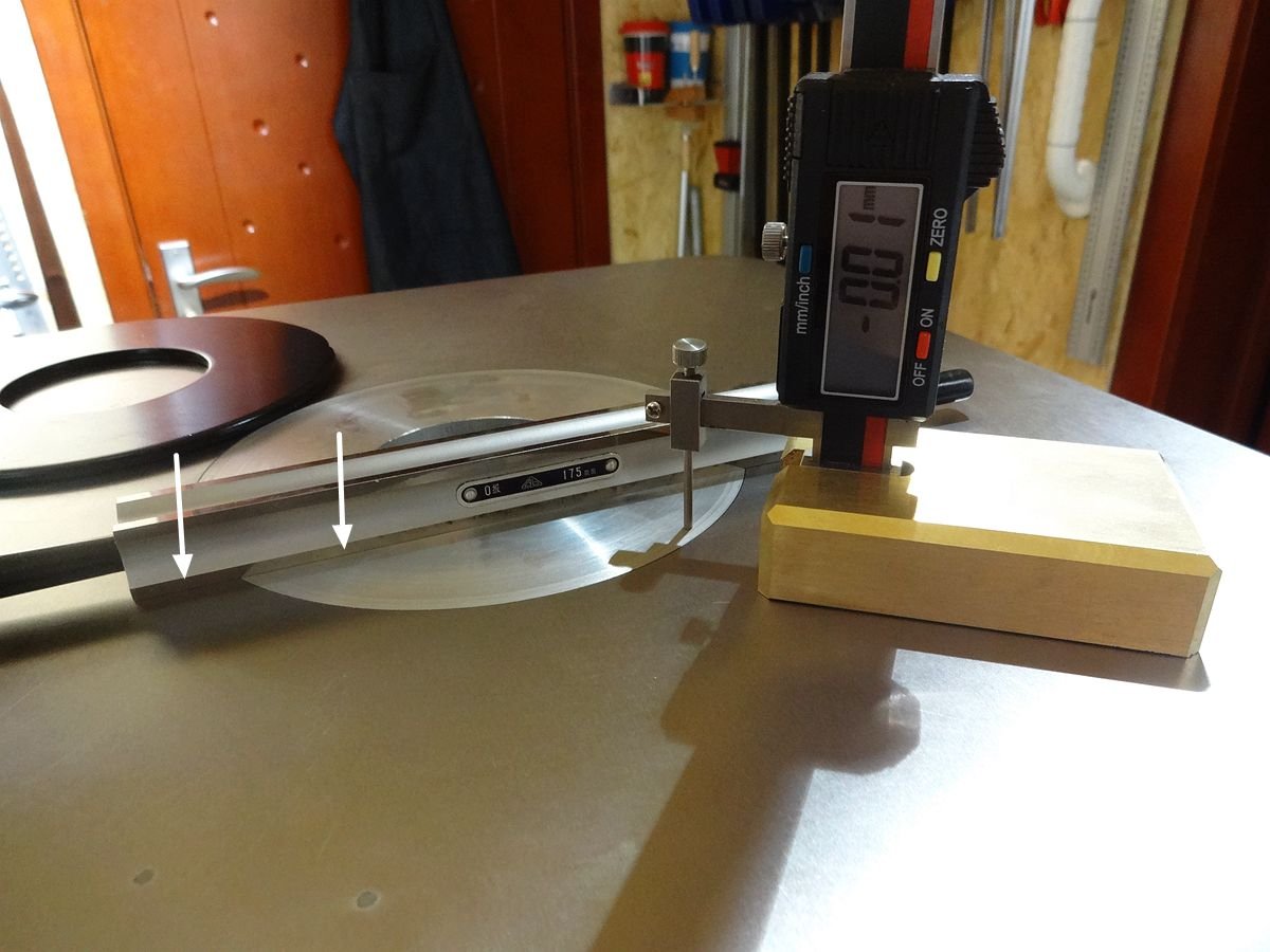
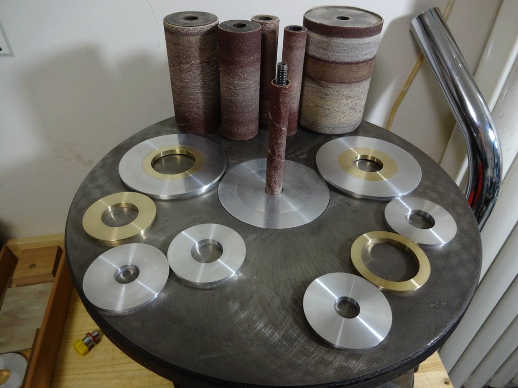
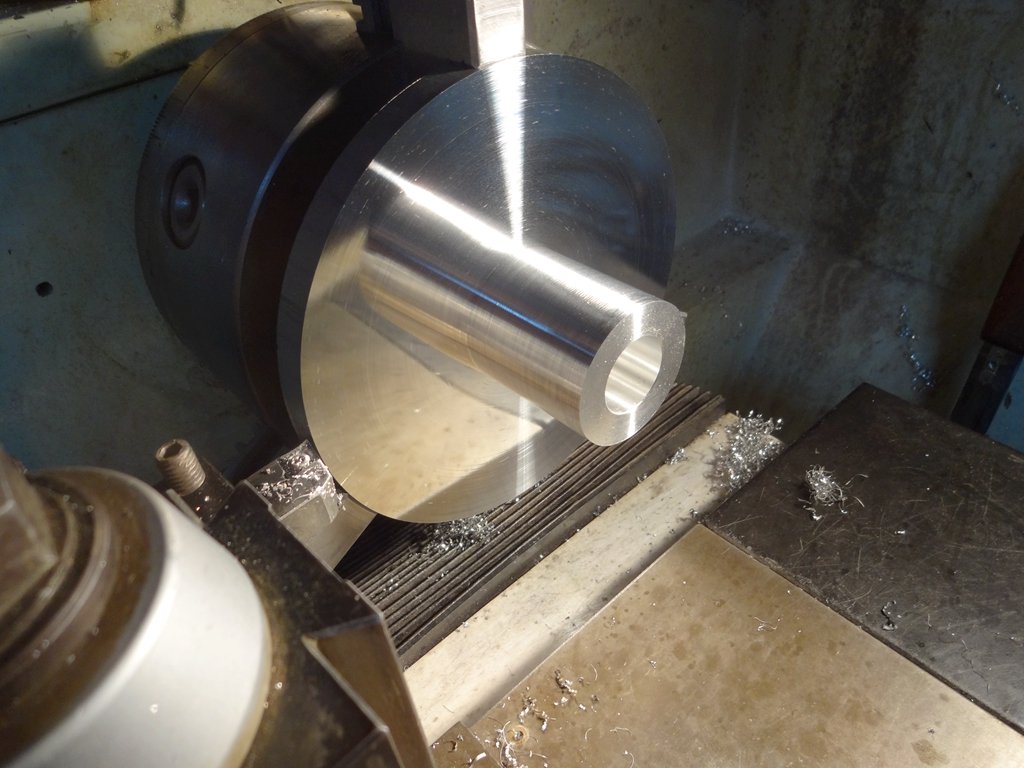
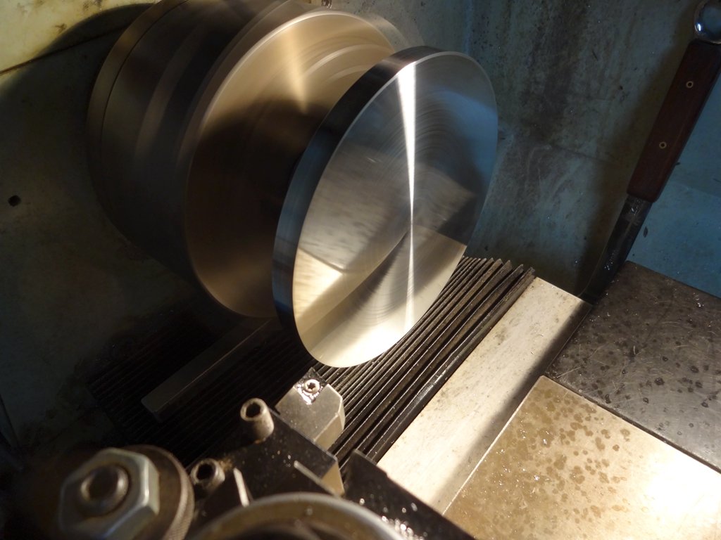
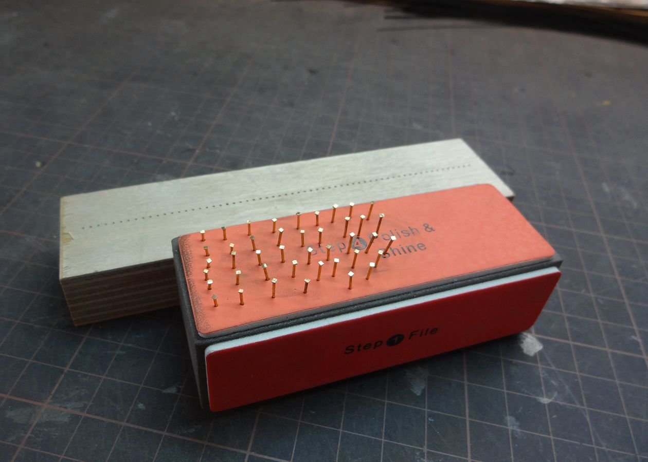
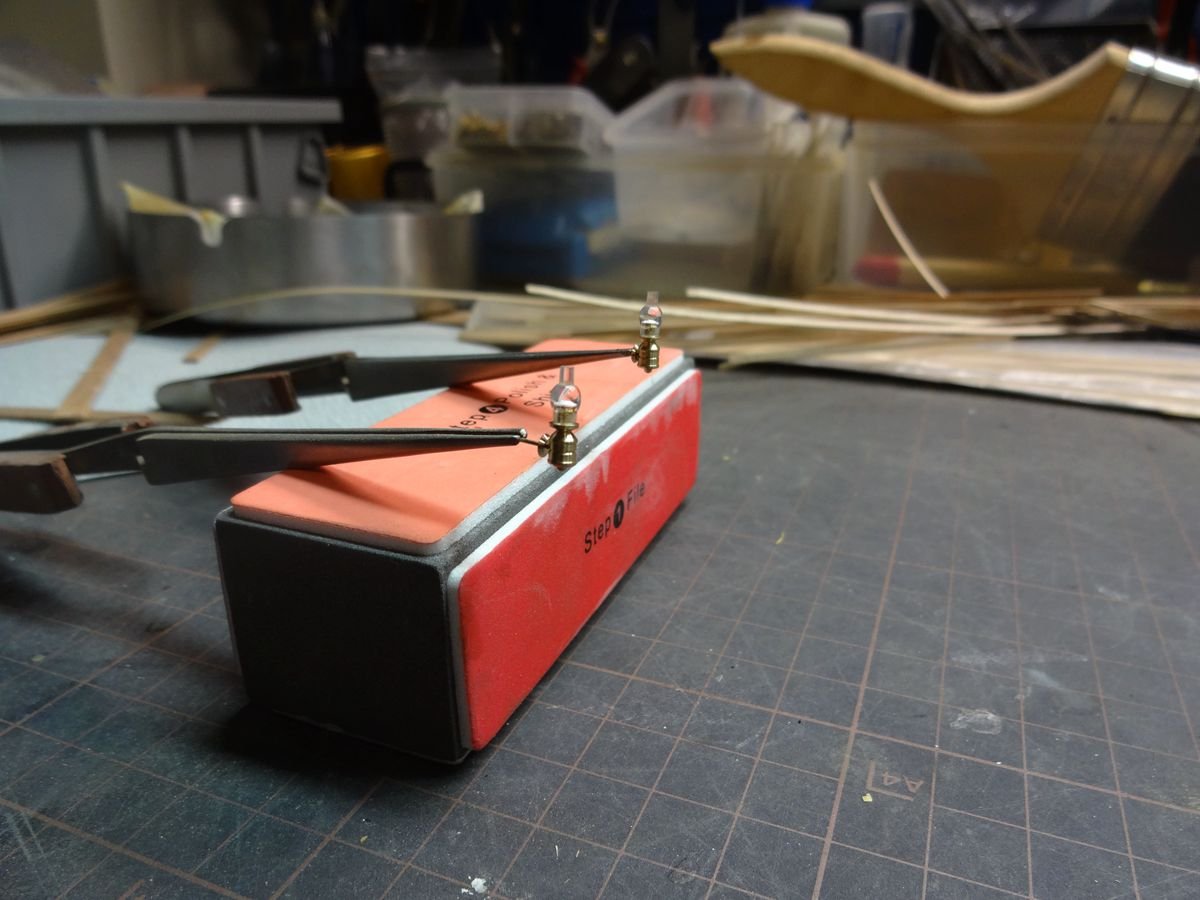
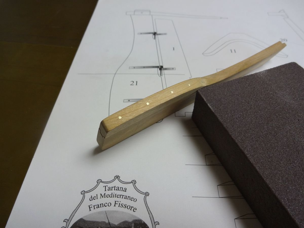
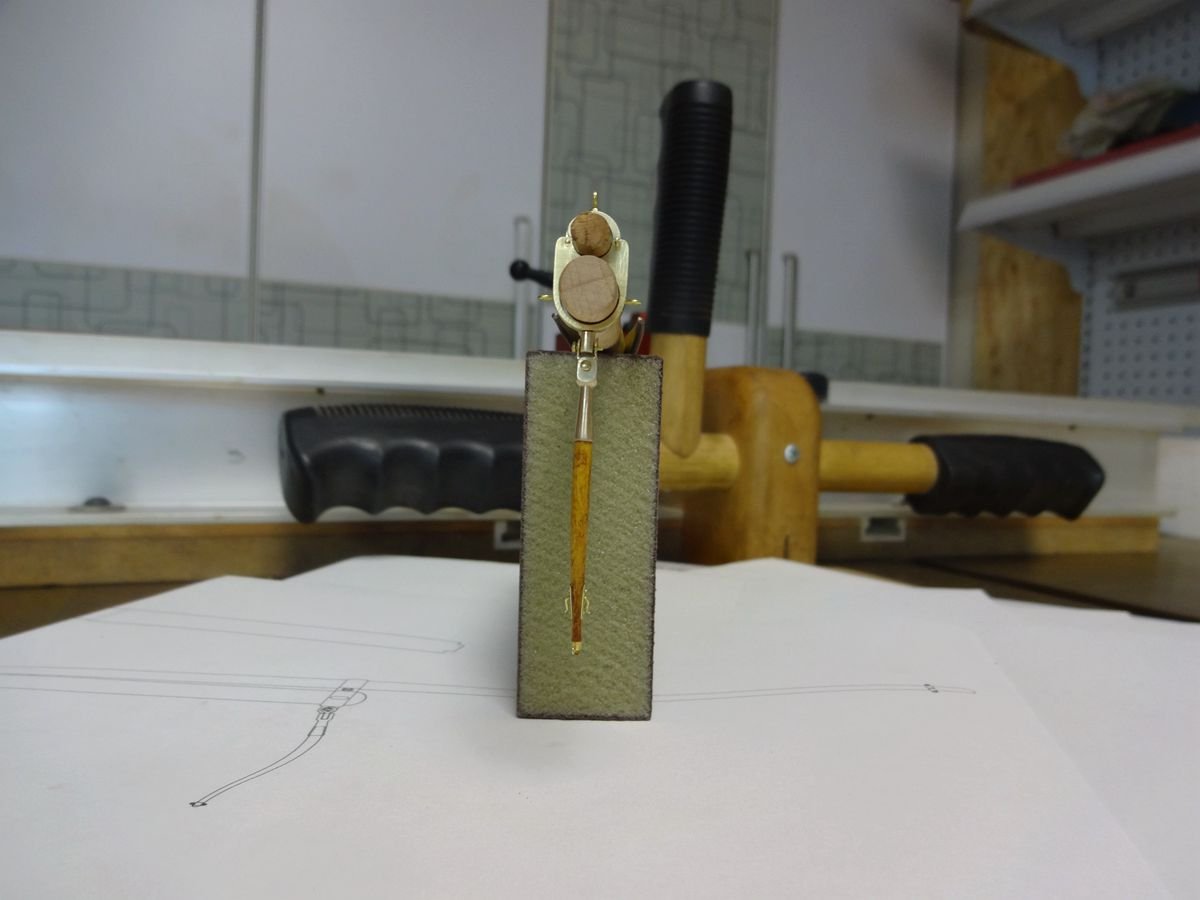
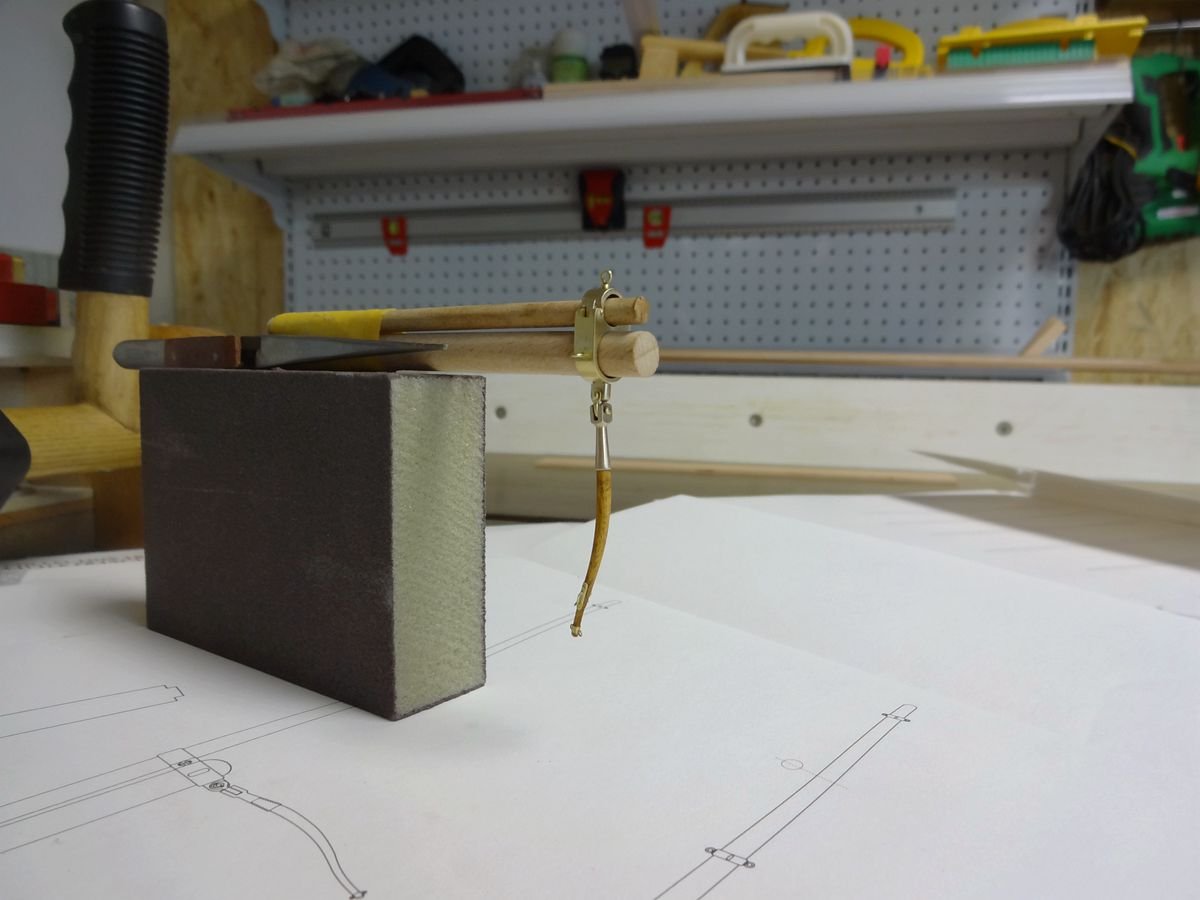
I have two sand bar machines for grinding curves. However, there is a common problem: The gasket uneven caused when grinding the end of the workpiece can not ensure that vertical. In particular, smaller parts are more prominent; and the spacer between the gasket and the sand column is often too large to cause small parts often involved. So the use of their own aluminum and brass turning, to ensure that the deviation control in the minimum range.
- paulsutcliffe, mtaylor, KeithAug and 5 others
-
8
-
-
-
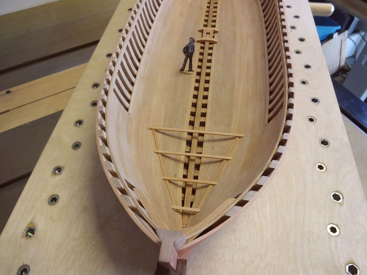
19 hours ago, G.L. said:
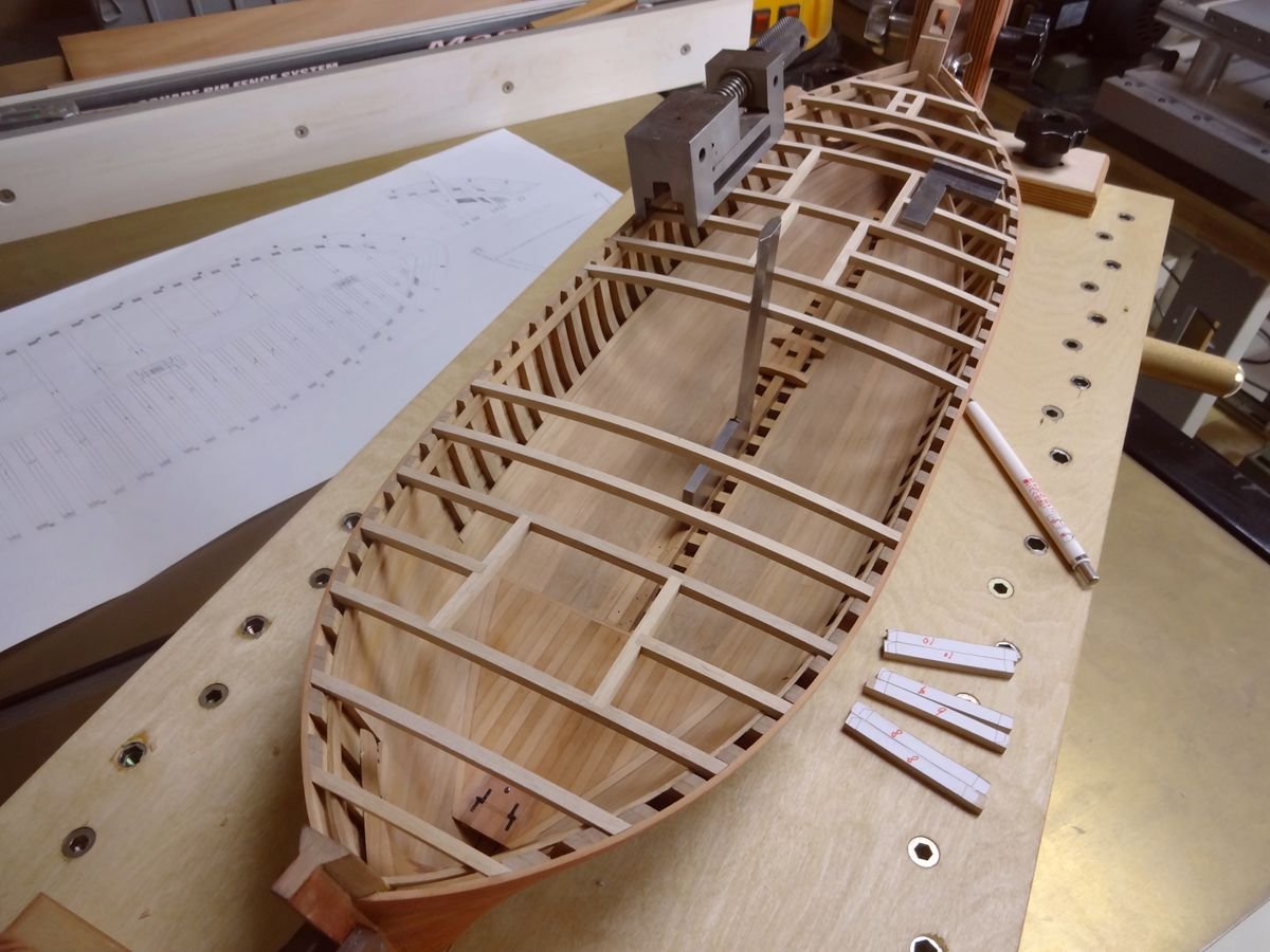
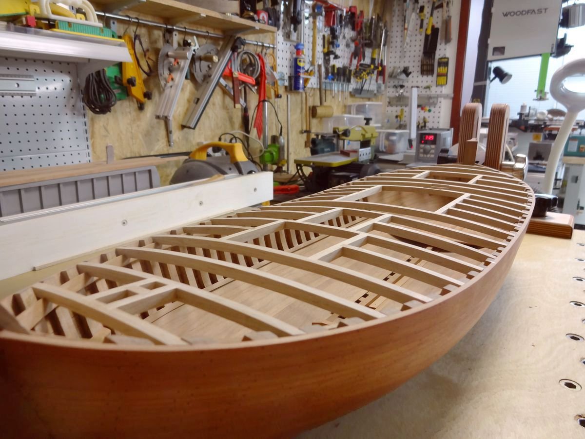
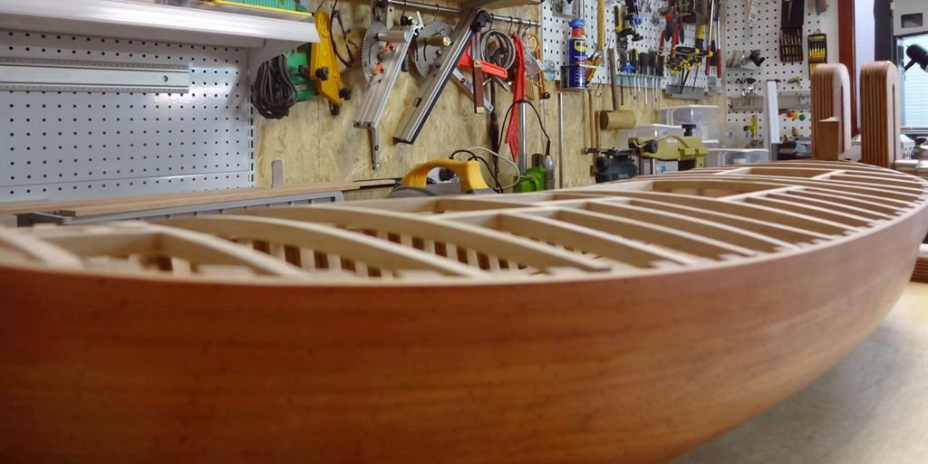
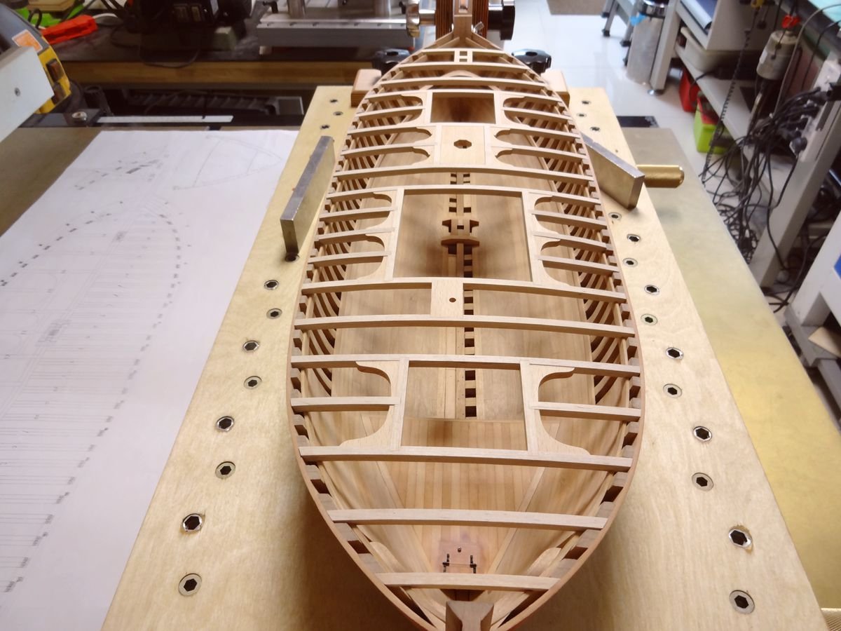
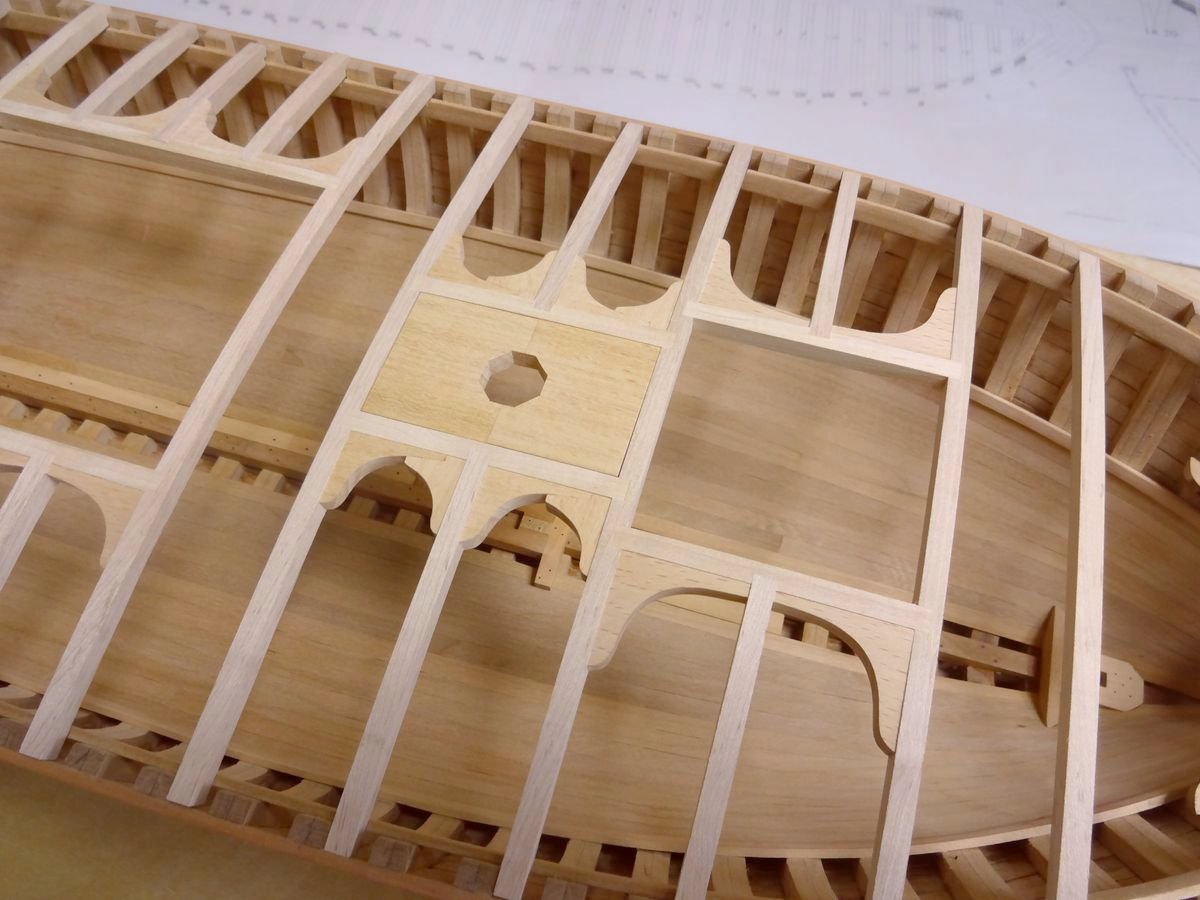
Whaw, that goes fast. And such a clean joinery! I wonder how you get it done.
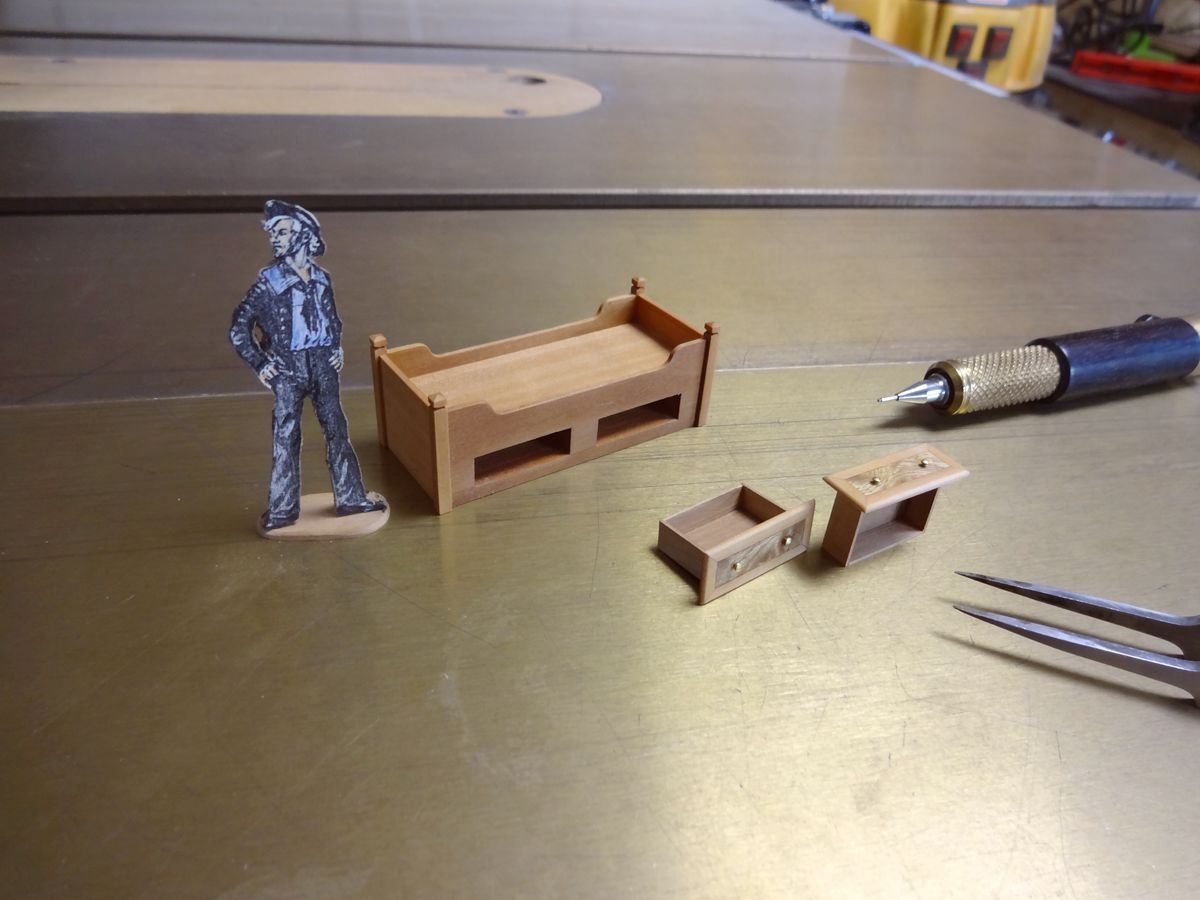
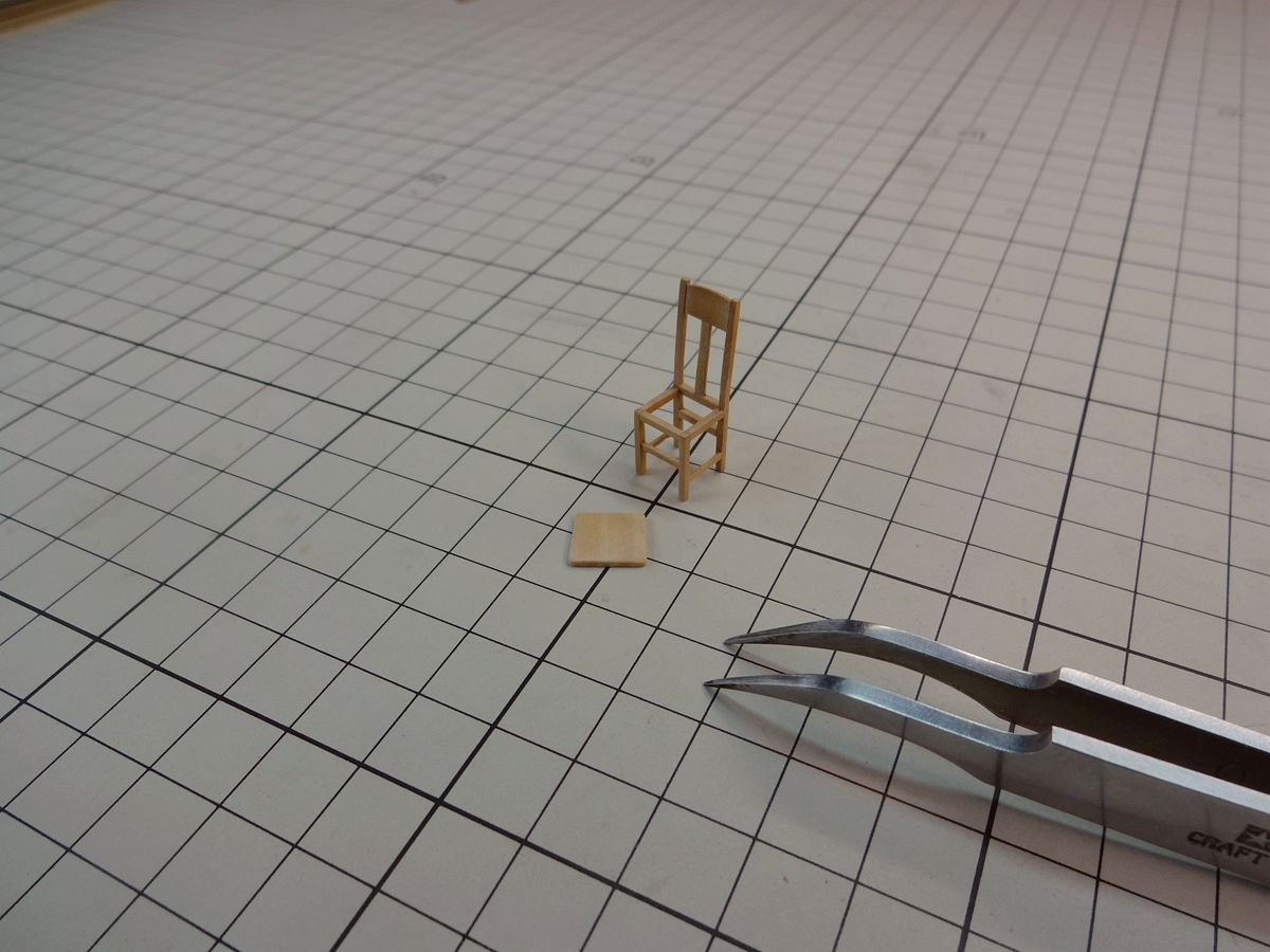
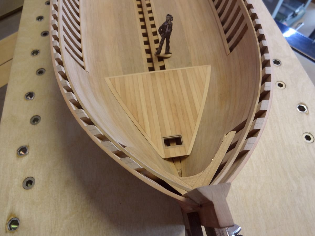
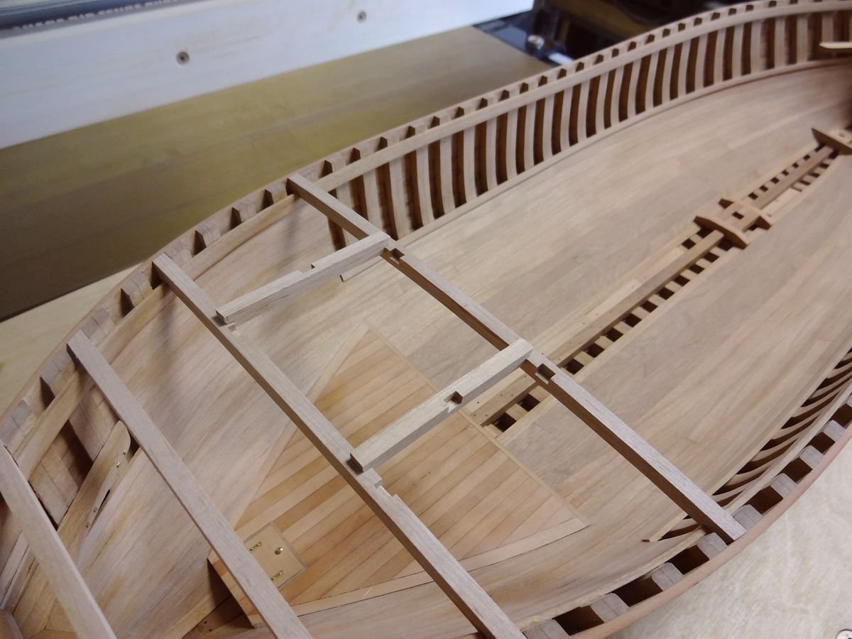
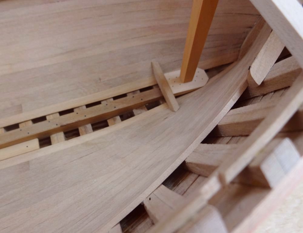
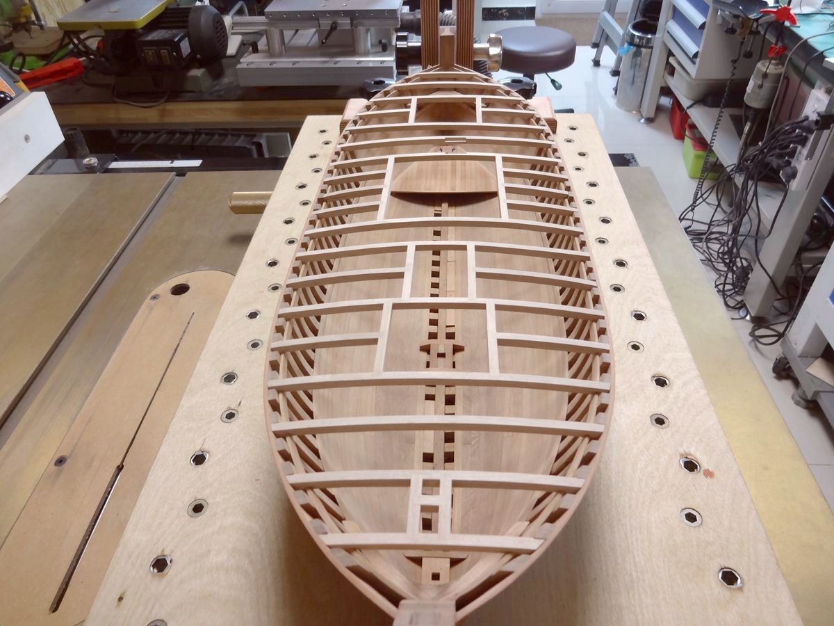
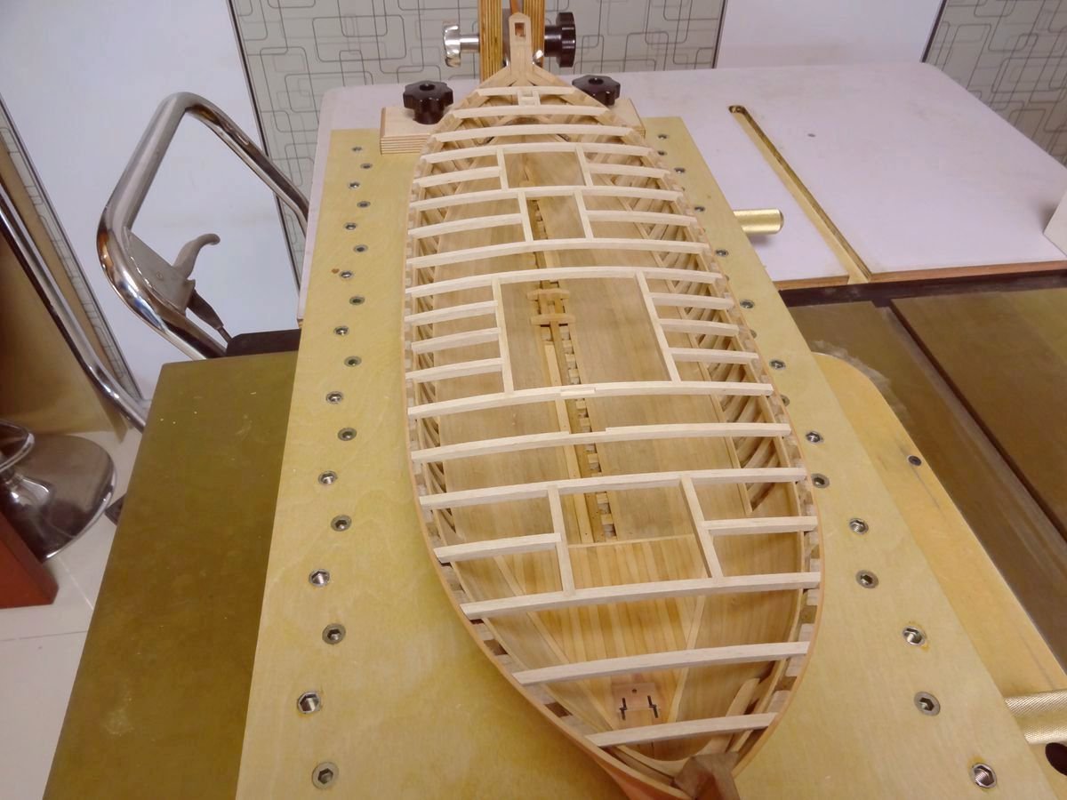
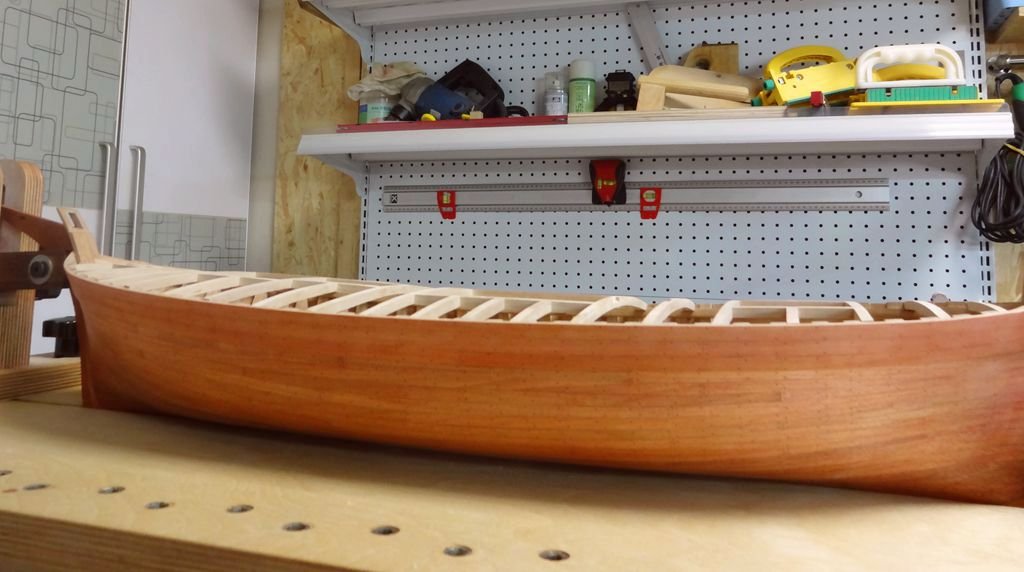
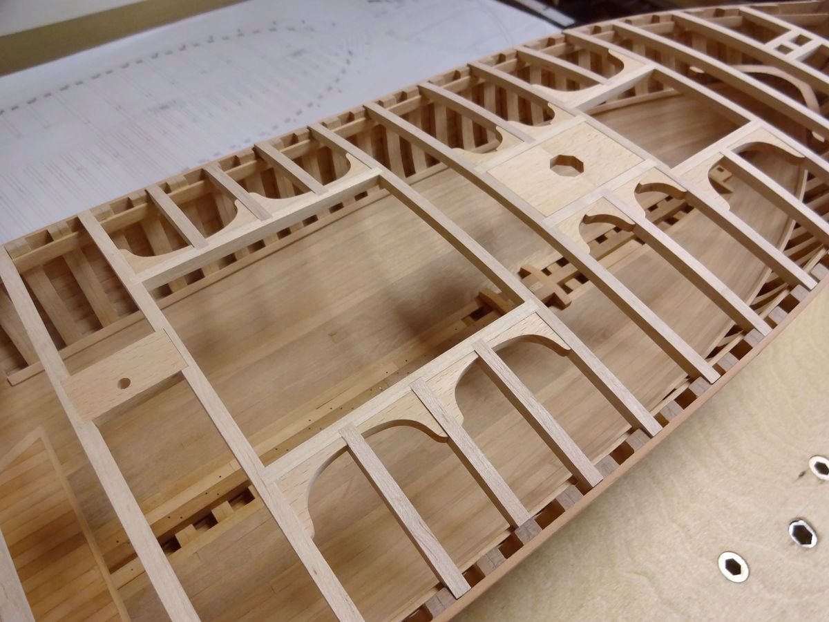
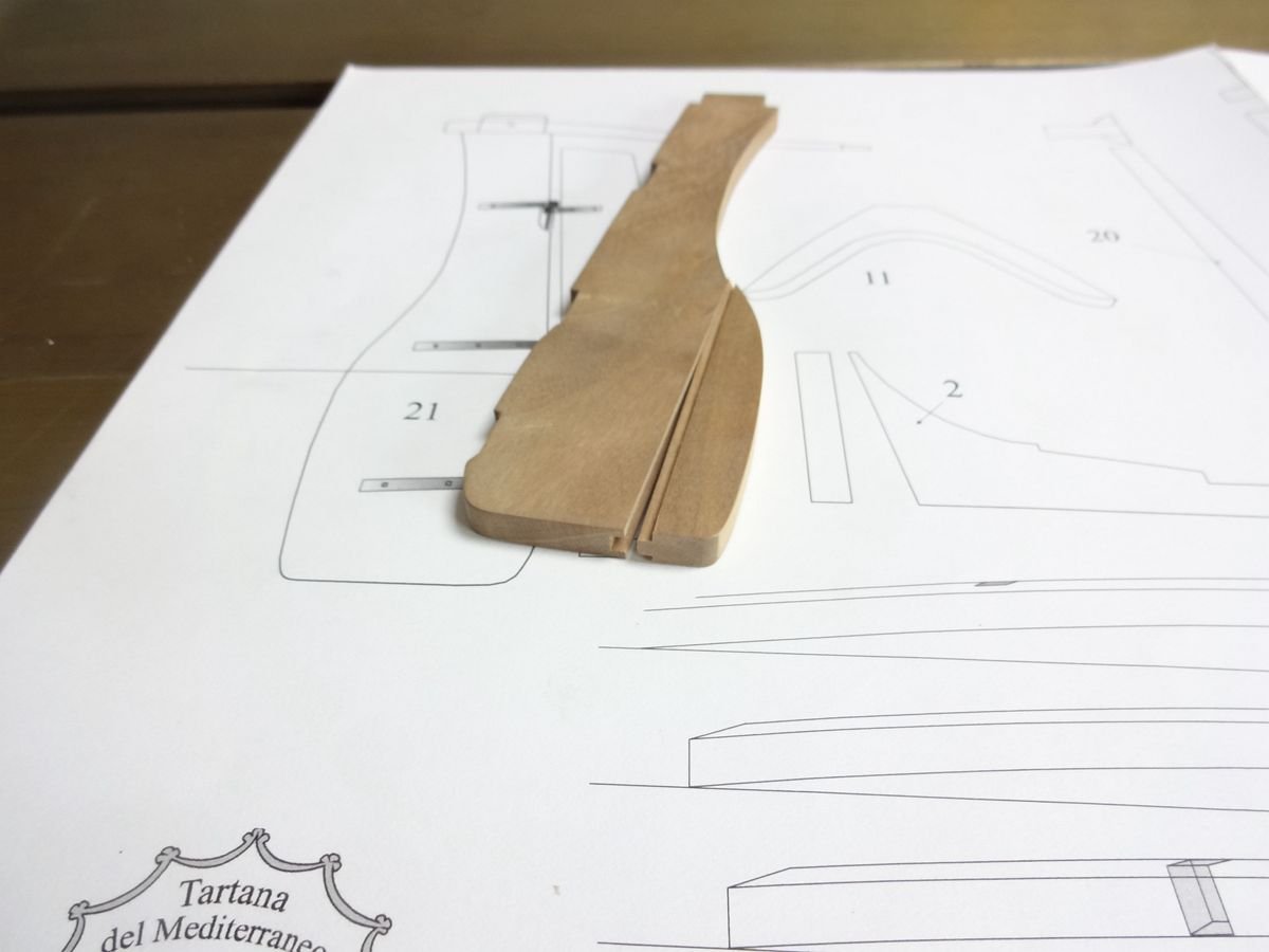
I've been working since the middle of last September. I usually have enough time, so I have enough patience to finish it. No less than 10 hours a day. Except for machining, most of the parts are done by hand. I am very concerned about the cleanliness of the work environment, not only to reduce the dust caused by the processing bias, but also to accurately find the tools I need.
-
-
-
-
-
11 hours ago, Kris Avonts said:
Hi hyw,
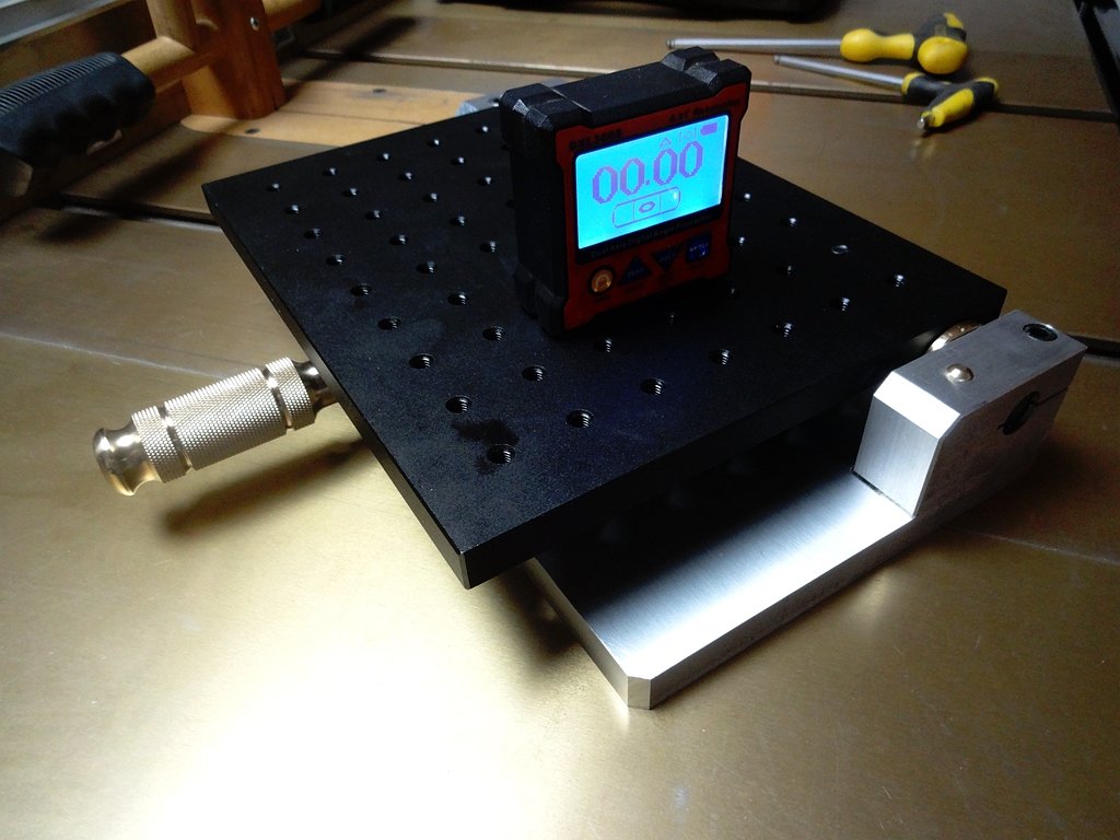
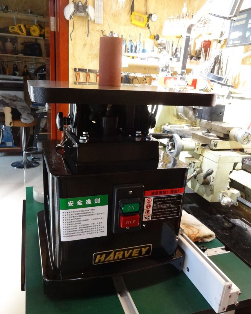
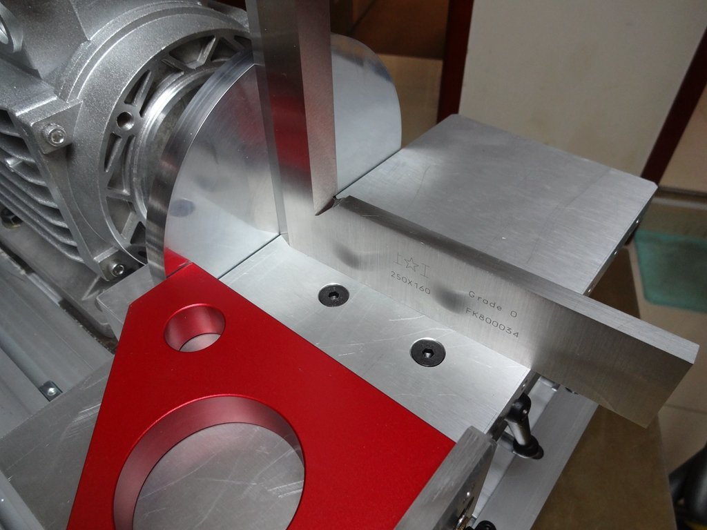
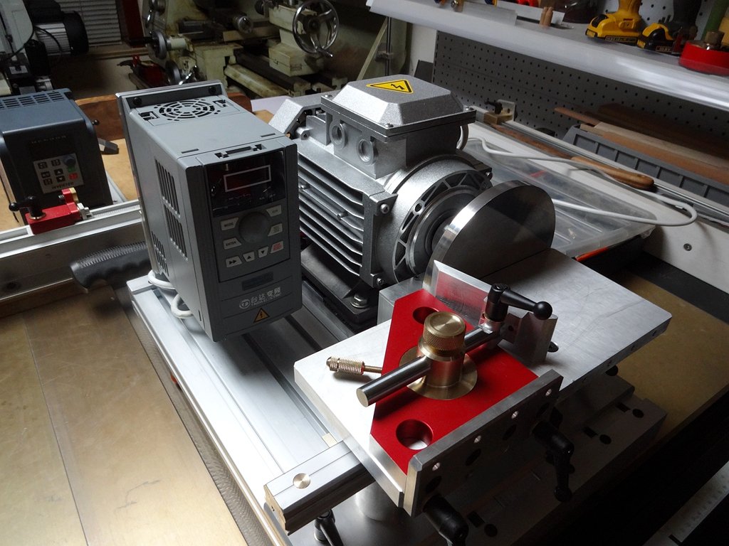
That's a nice piece of machinery. Based on the size of the square (250x160) I estimate the sanding disk to be 125 mm in diameter.
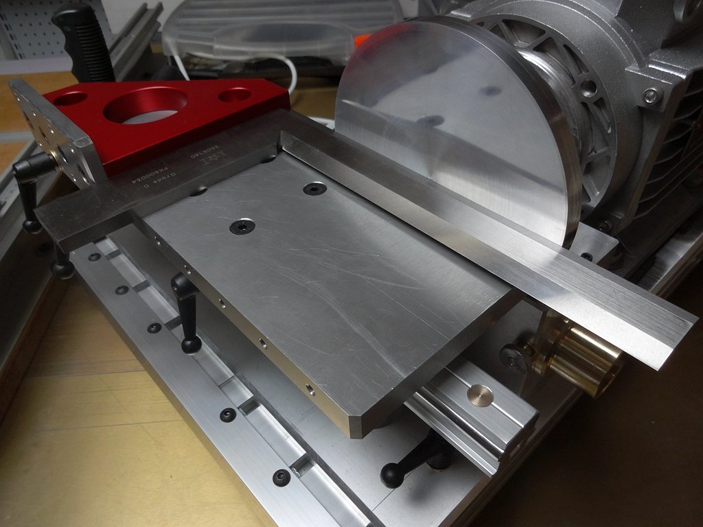
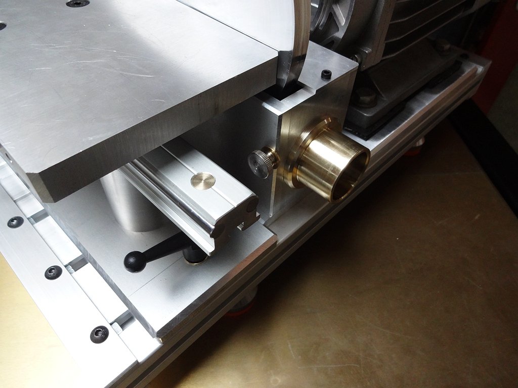
The table is 200x100 mm (?) and sits on a linear guiding rail, but how do you tilt it?
And a last question: this seems to be a 3-phase AC induction motor with frequency converter, but what is its power rating.
It looks quite heavy for working with wood pieces of the size most used by modellers.
Anyway... this is well done.
regards,
Kris
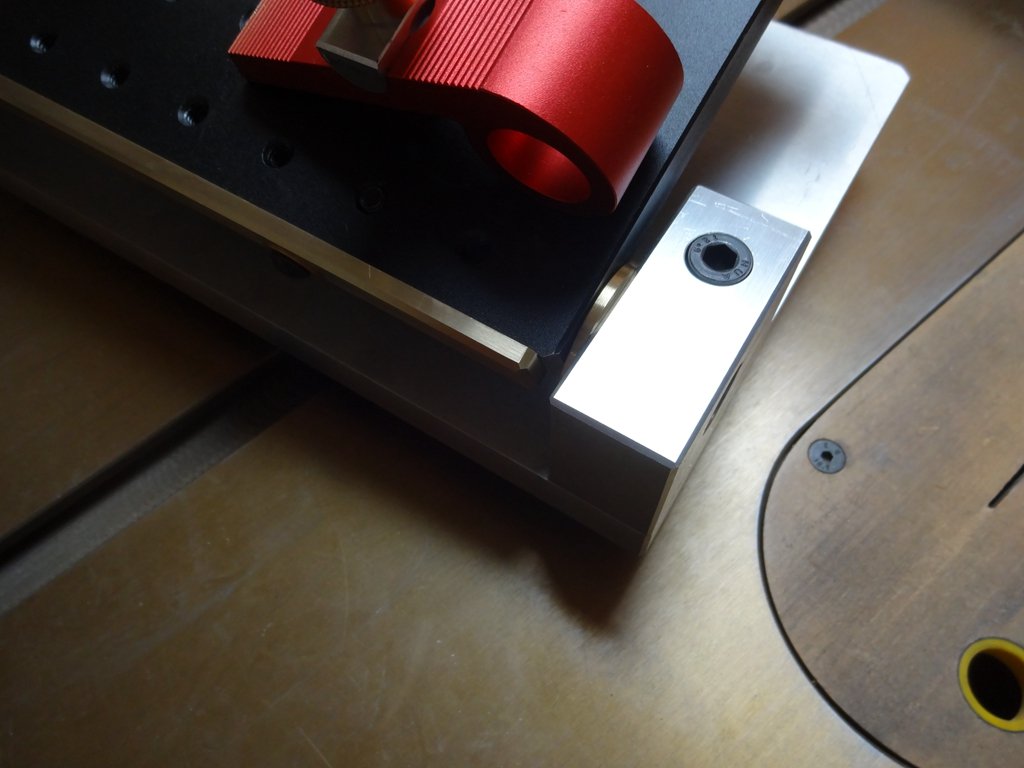
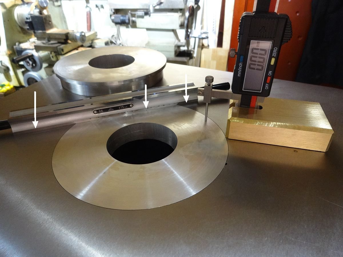
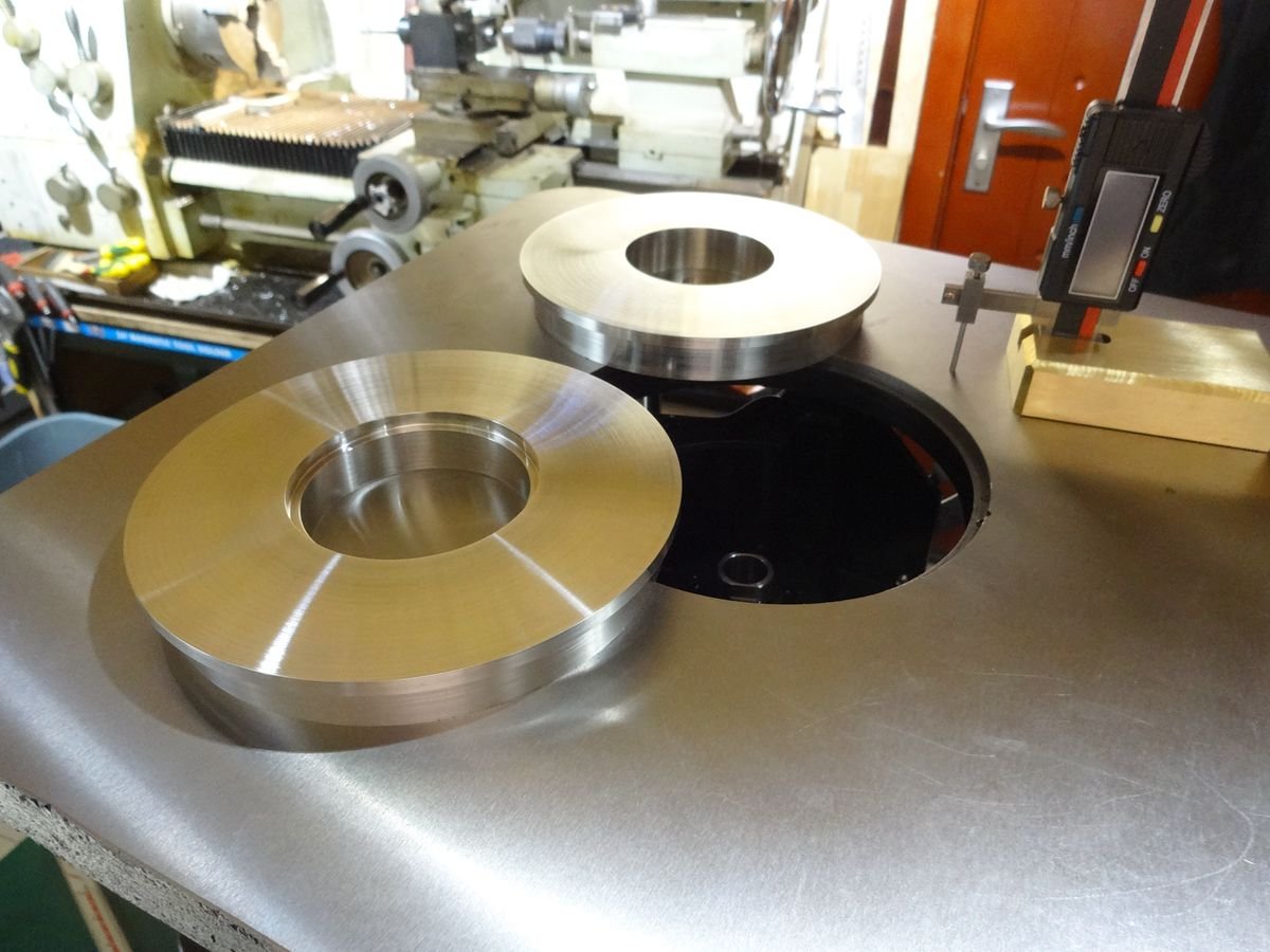
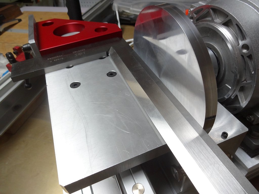
Hi Kris, The diameter of this sand table is 150. As a high precision grinding tool, the more the joints, the greater the deviation; in the effective range of grinding, whether horizontal or vertical, the role and stroke is the same. So I through the table on the backrest design angle adjustment to achieve the "tilt" function. It's much more stable on the countertop. Because of the need to polish the metal parts, the motor has a power of 750w; the weight is about more than 30 kg.
-
15 hours ago, Moab said:
This really looks great! I know nothing about motors but does “frequency control” mean variable control? What was the total cost of the parts?...Moab
Hi Moab. By changing the frequency speed, the basic loss of torque output, than the usual current speed is much more stable. The cost per unit must be much higher than the cost of mass production. . .
-
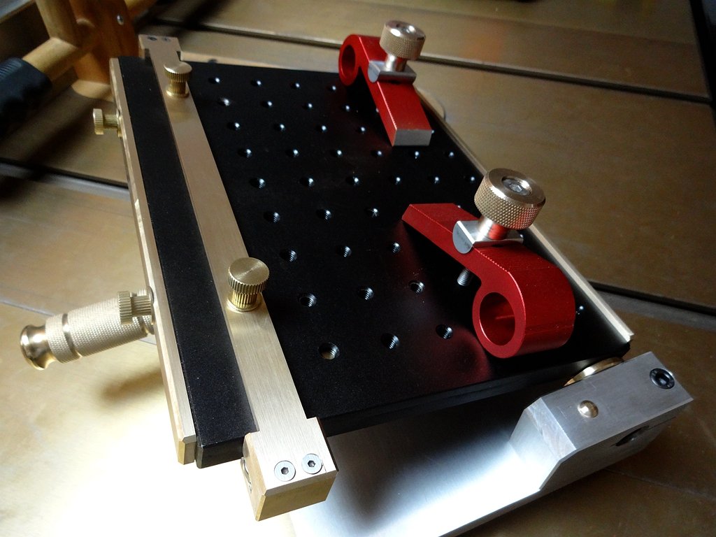
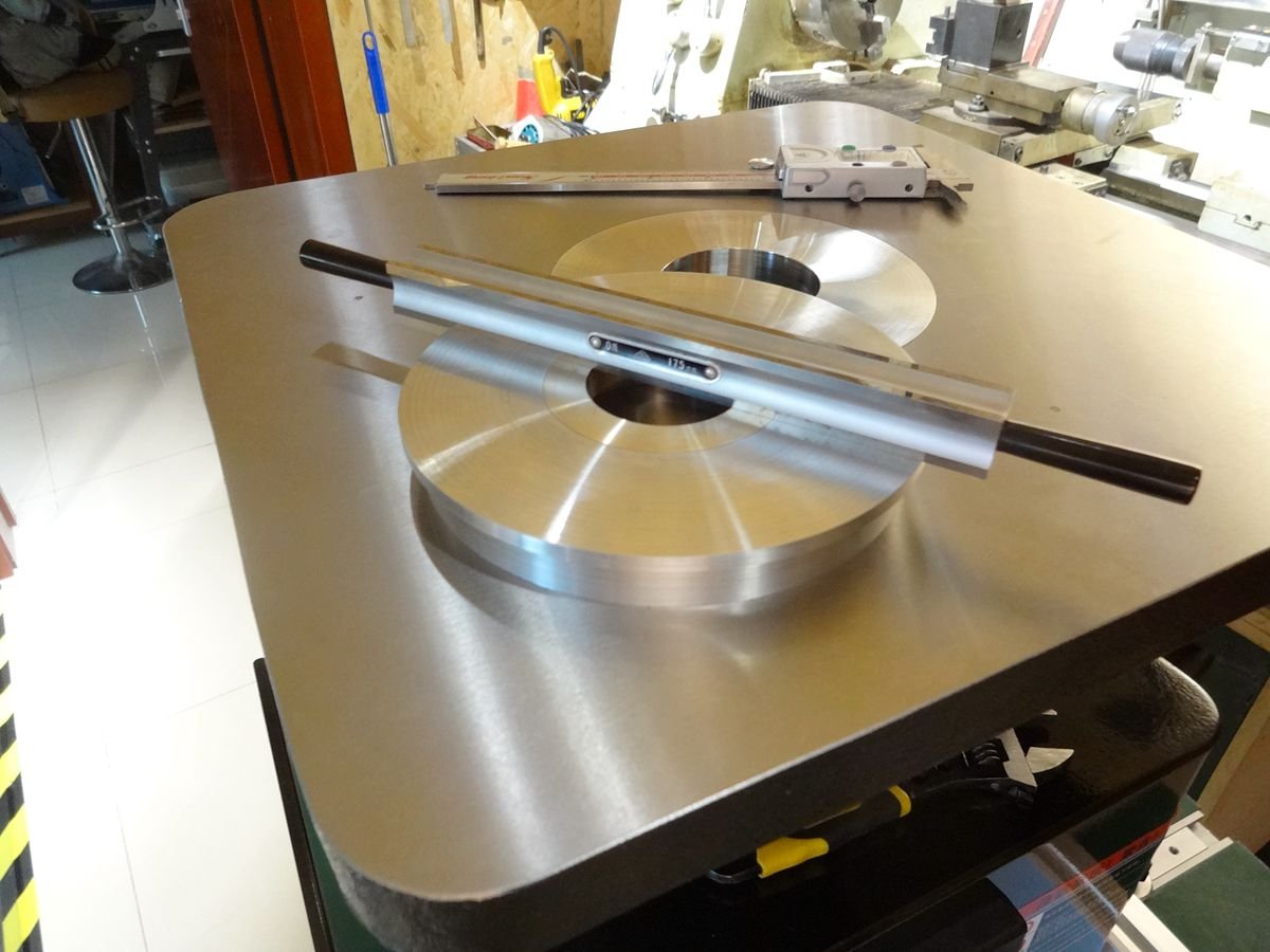
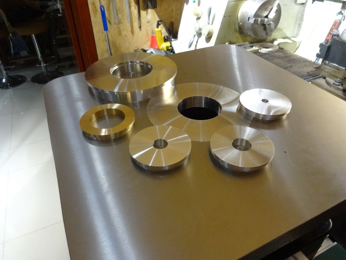
Self-made sand disk . Three-phase motor frequency control, can achieve accurate grinding, chamfering, low speed does not affect the torque output, ultra-low noise night operation. The table surface of the two-axis slide rail can be moved and polished, and can also be locked at any angle. The sandpaper can be quickly changed by hand by turning two nuts on the dust-collecting cover. High precision machining ensures minimal deviation and in some cases can be used as an alternative tool for milling small parts.
-
5 hours ago, BANYAN said:
Thanks for the explanation; they are among the best fittings I have seen made - you truly have a remarkable talent.
Thanks for sharing
Pat
Thank you for your comments. I came to this world-class Forum through the introduction of friends, very like the atmosphere and environment here, hope to learn a lot of master works can improve their level, do my best to do each work.
- druxey, DmitriyMarkov, mtaylor and 1 other
-
4
-
1 hour ago, wefalck said:
I think we all would love to see photos of the processes, the stages of fabrication, and not only the brilliant products ...
I'm sorry I didn't live up to your expectations. Almost all of my work, especially when I'm working on a machine, I never take pictures that aren't relevant, just to be safe and to make sure there are no mistakes.
-
-
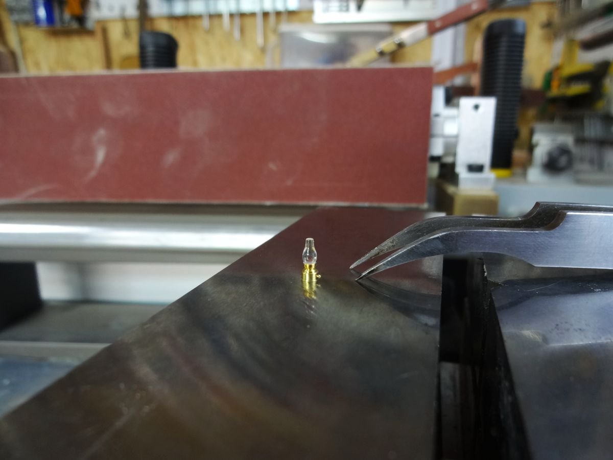
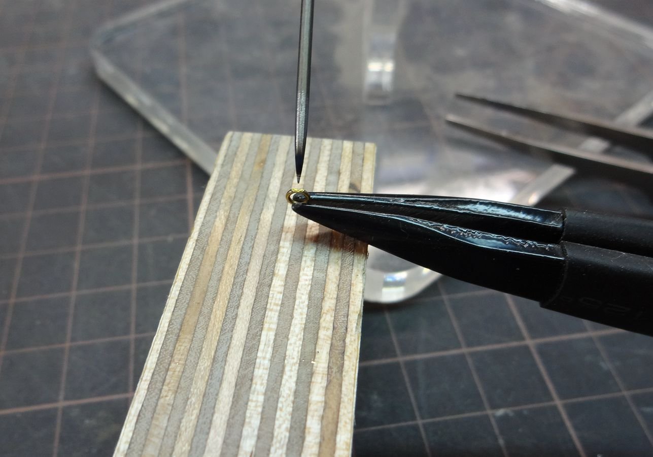
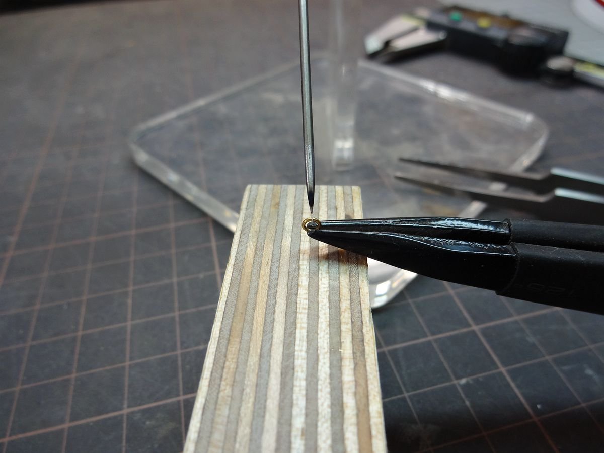
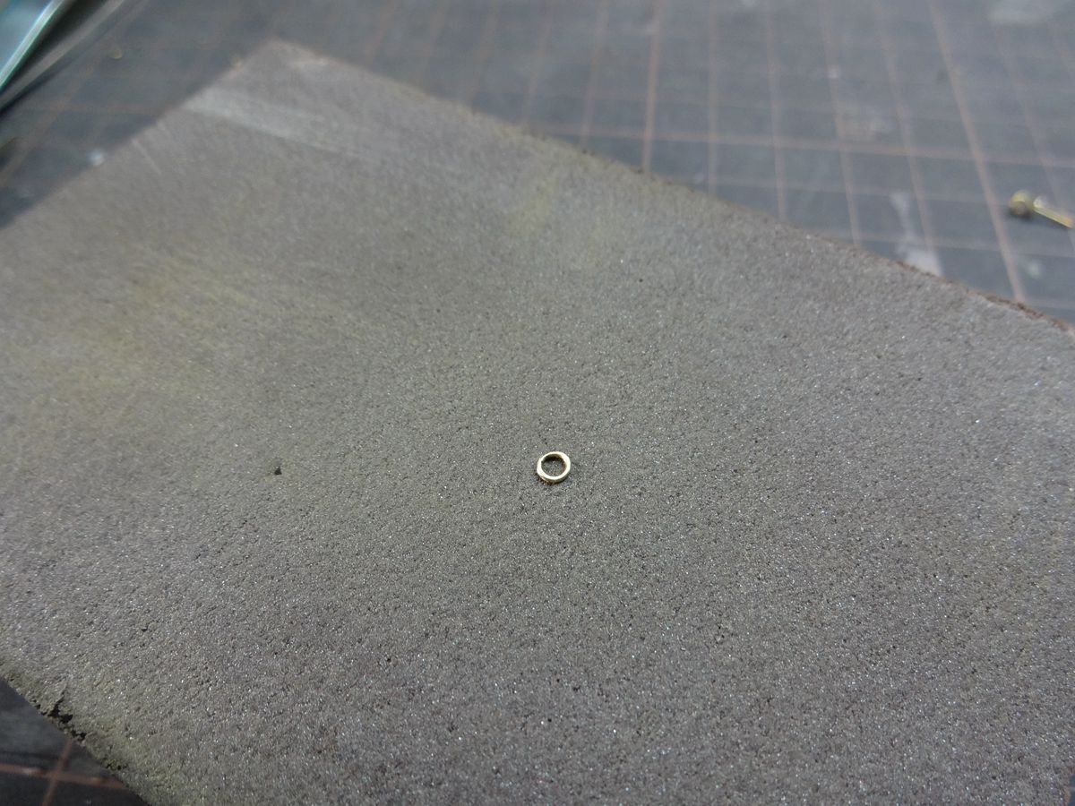
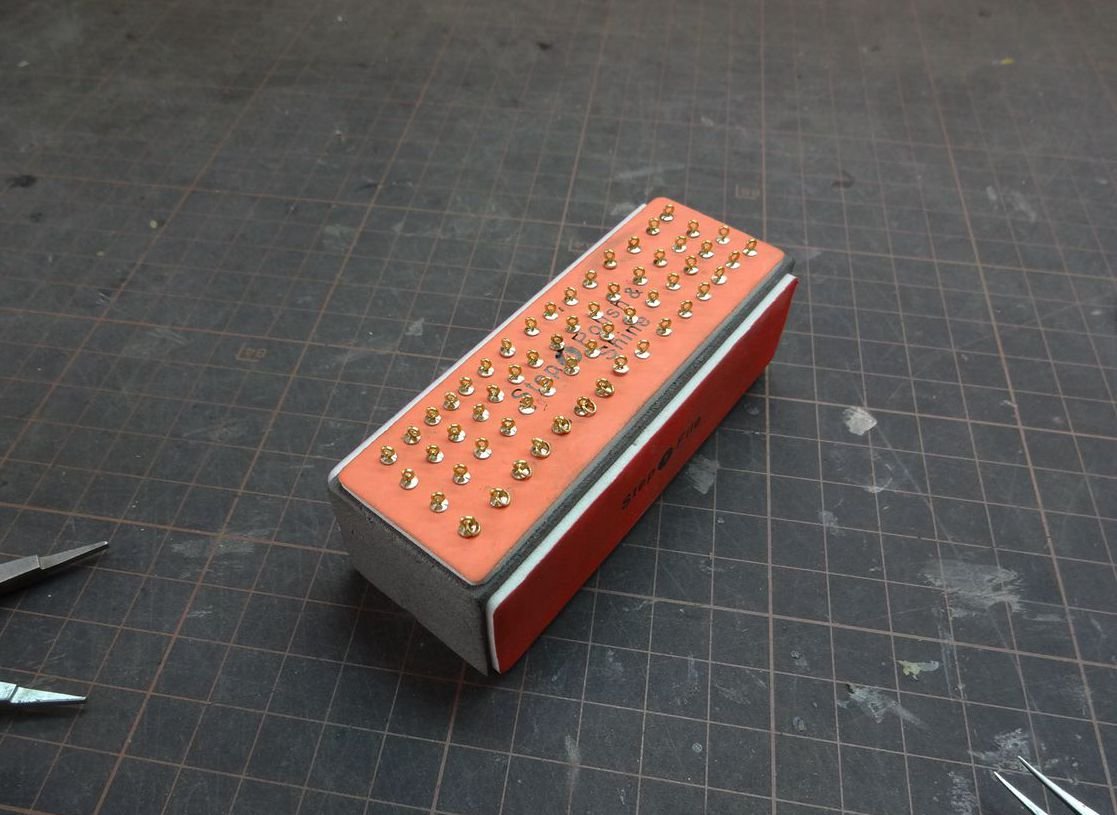
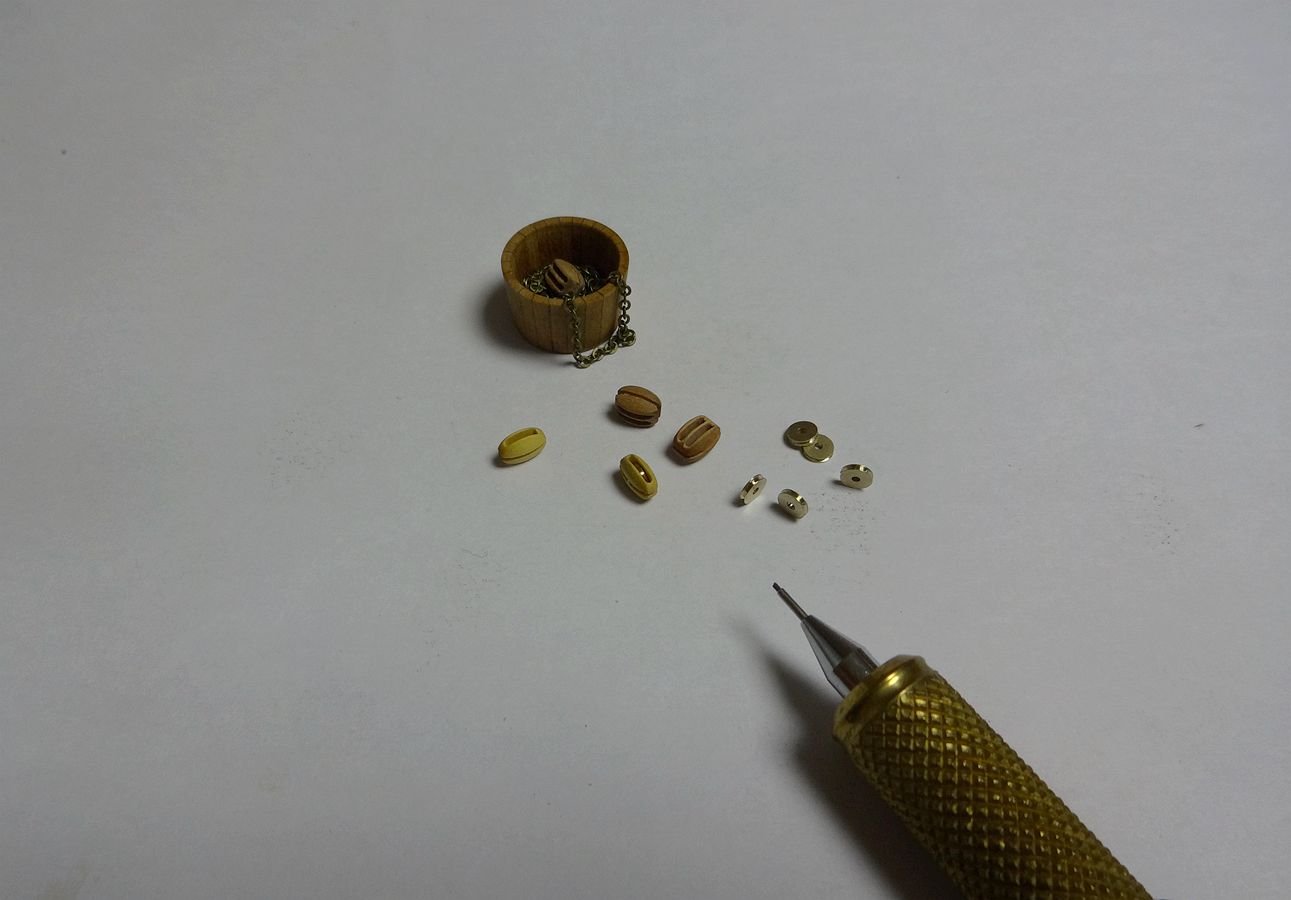
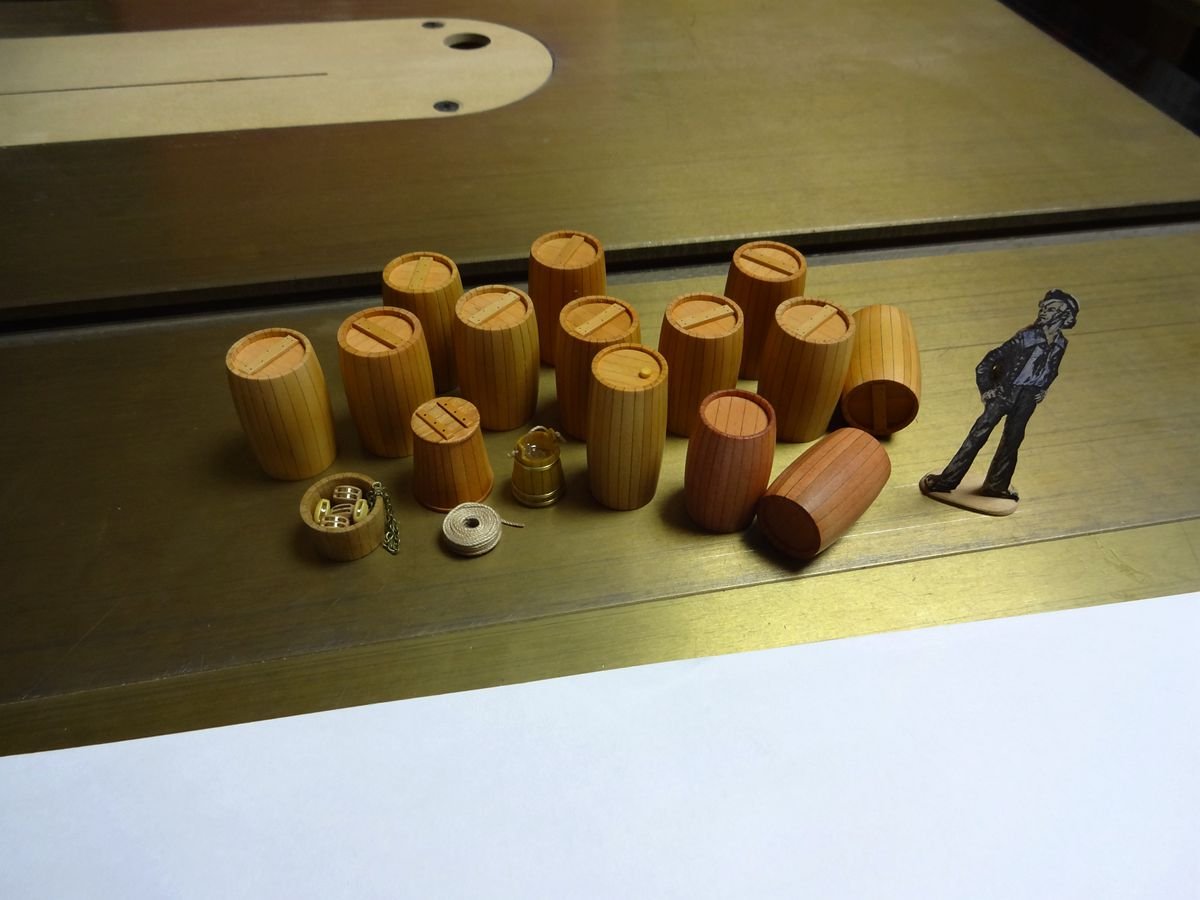
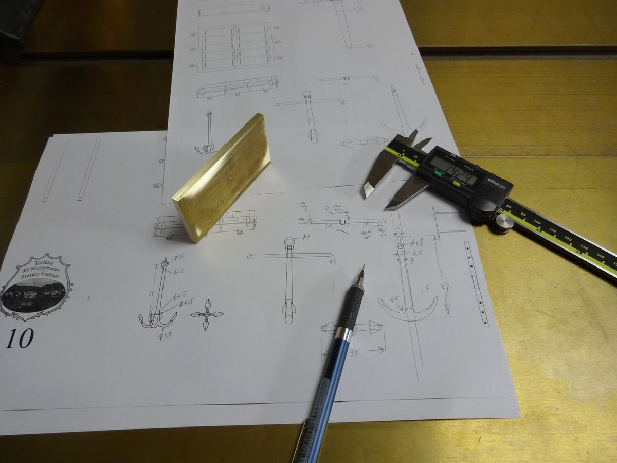
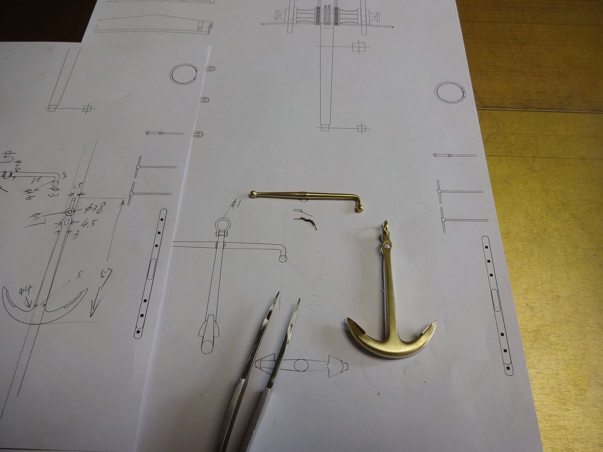
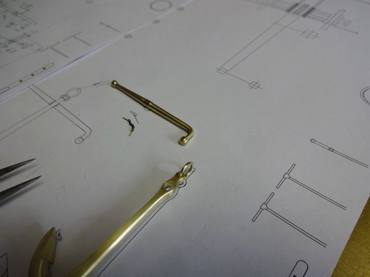
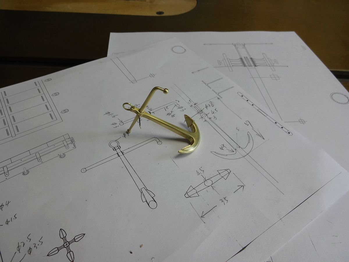
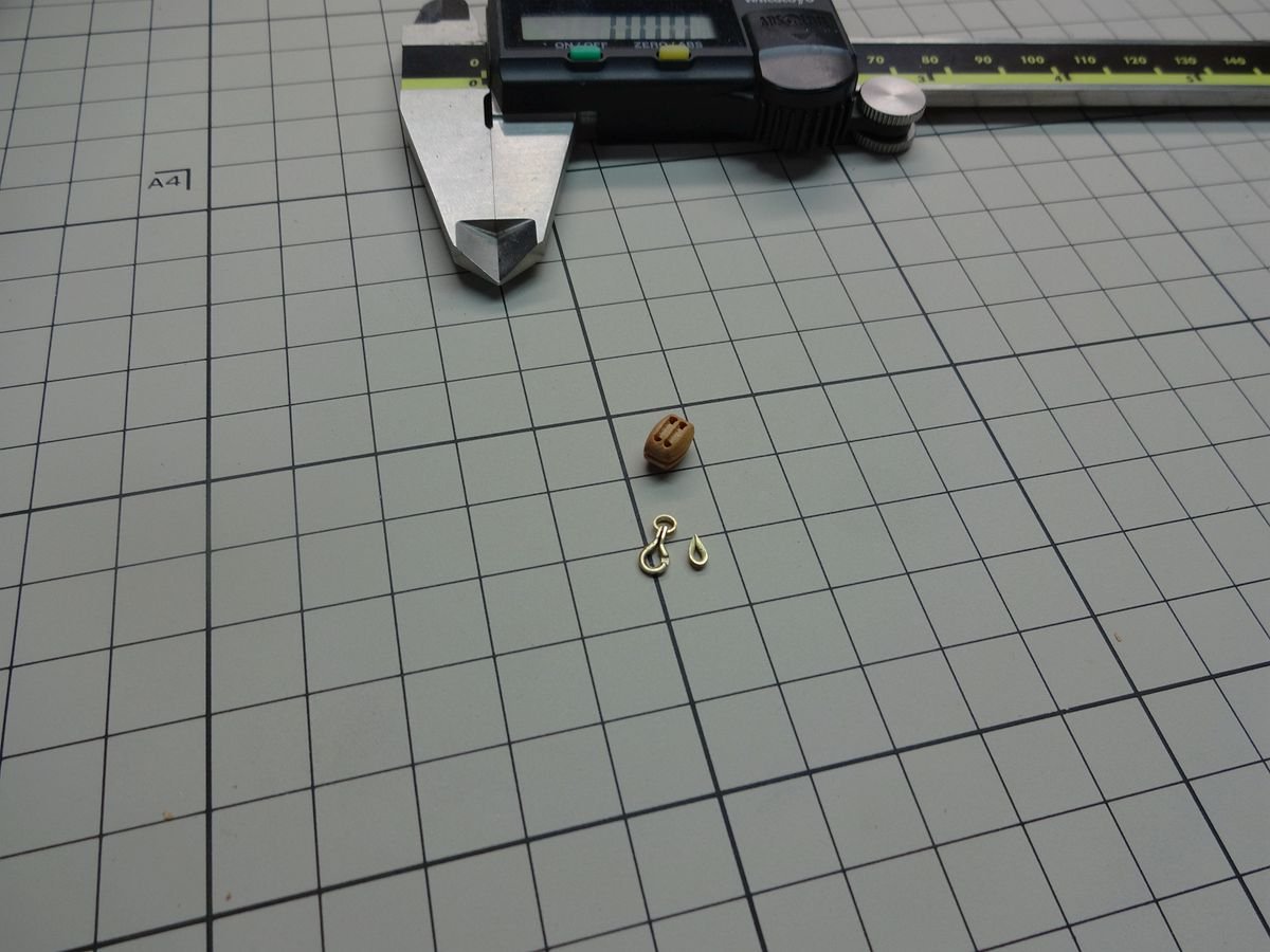
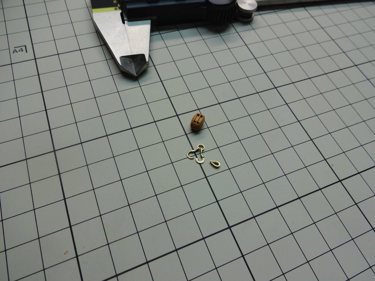
3 hours ago, BANYAN said:
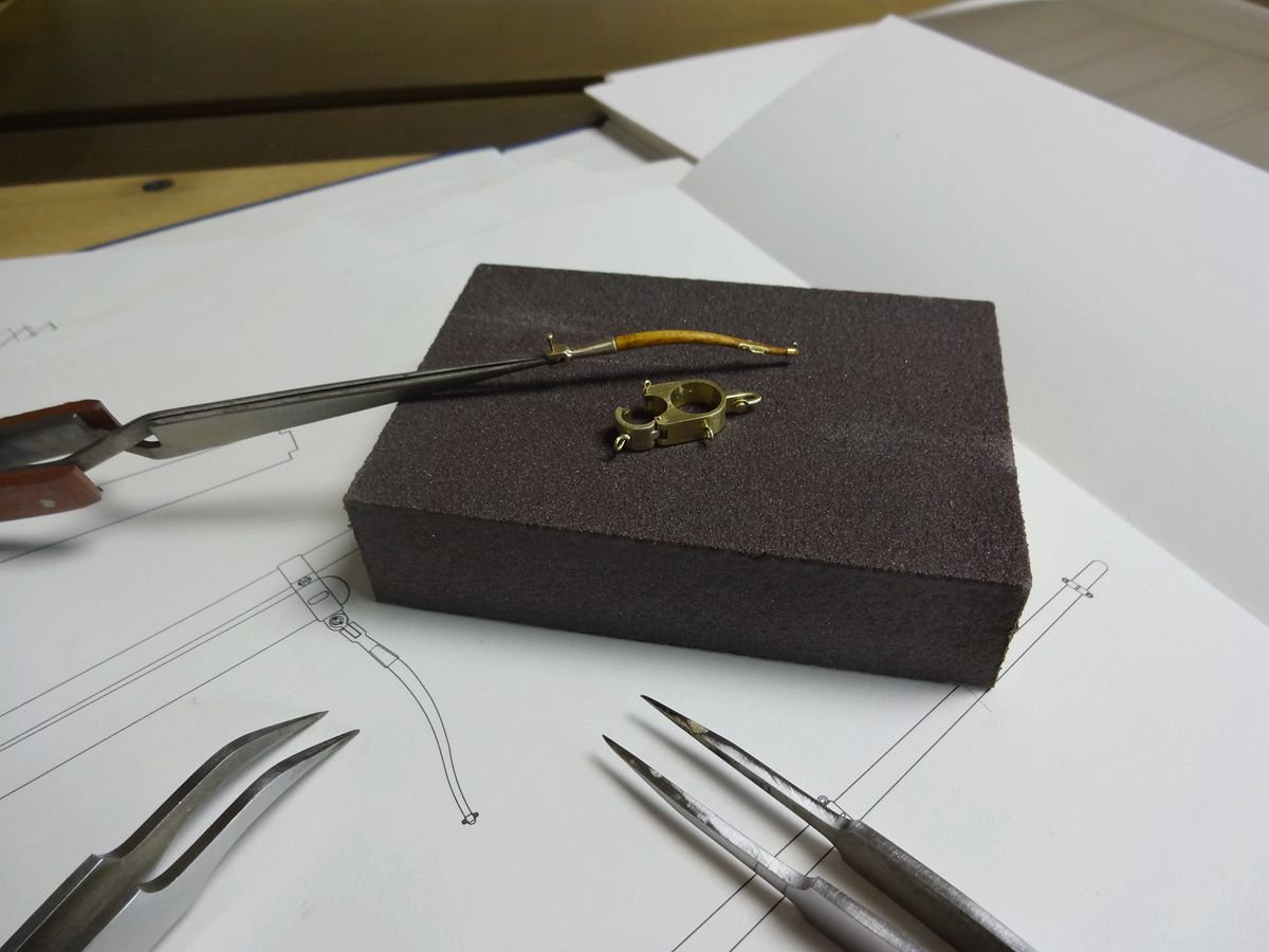
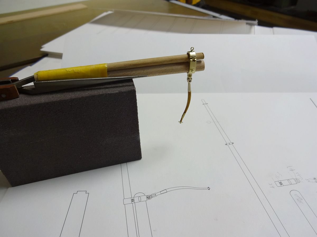
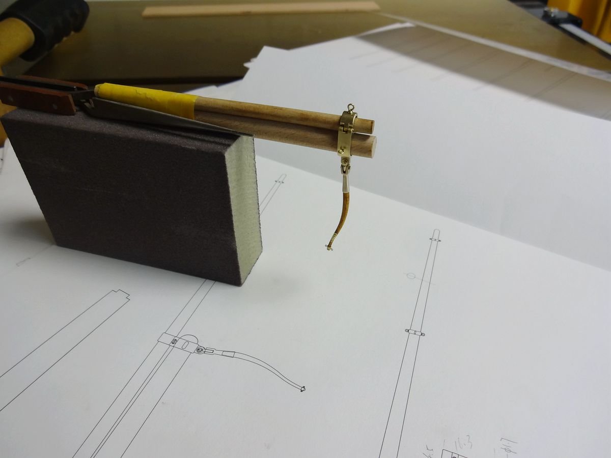
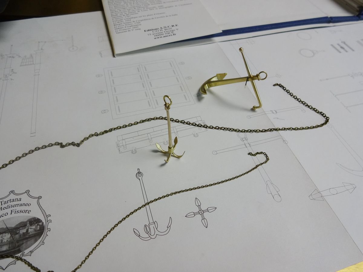
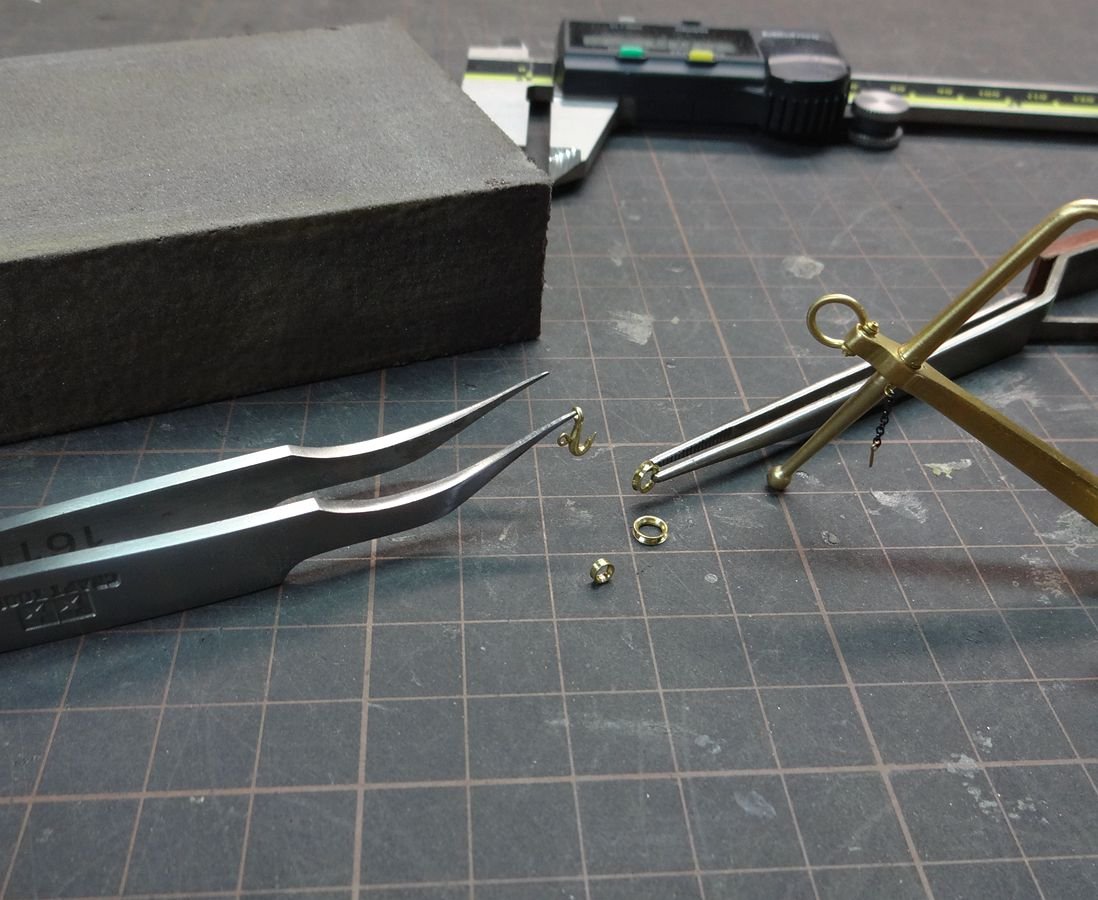
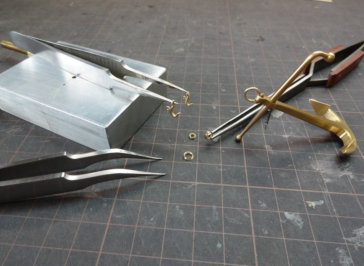
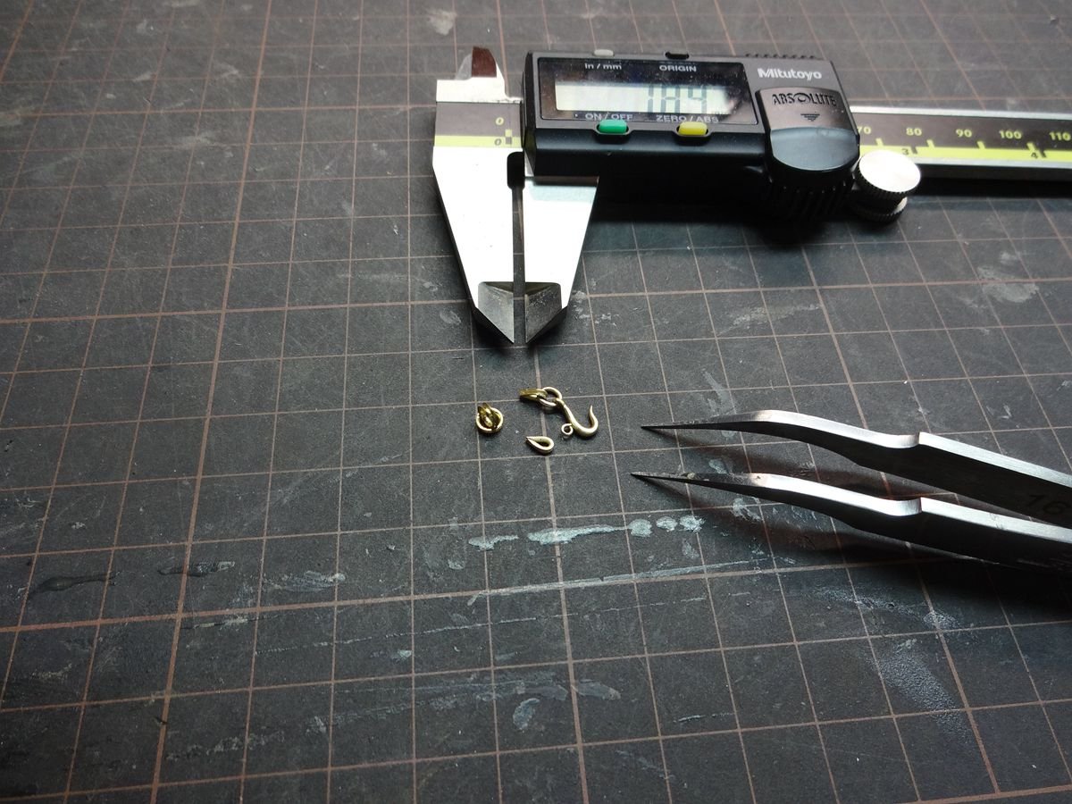
Stunning work! Did you make those thimbles, clew hooks etc yourself? If you did, could you please show us how you did it?
cheers
Pat
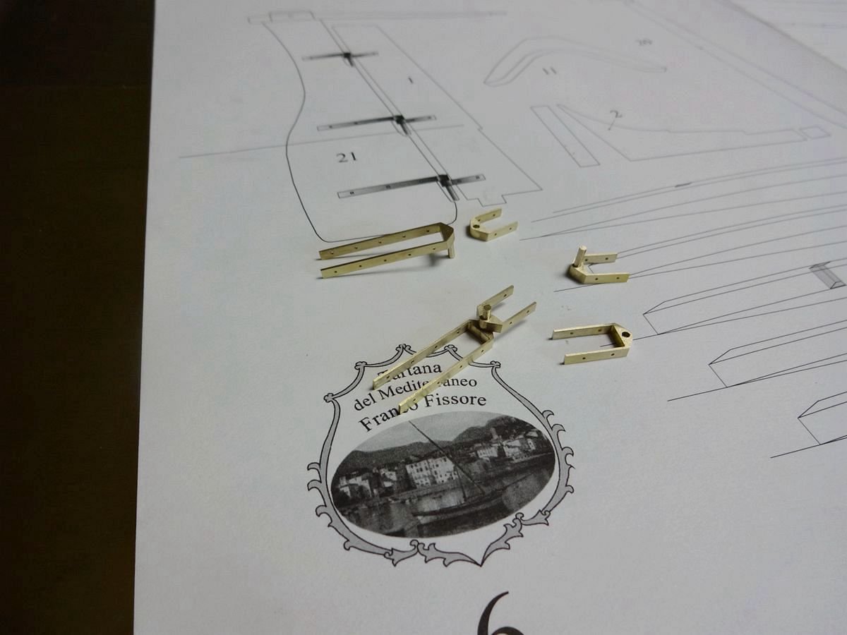
Thank you for your attention. Many of the unpublished tools in this image were created by me. I mainly use the lathe processing, milling processing way production. I also like to make any part of my model in these ways; after this piece is finished, I'll post another post about my various diy tools. Have a nice life!
- paulsutcliffe, druxey, mtaylor and 1 other
-
4
-
12 hours ago, Voyageur said:
If this is an advertisement for awesome clamps and tools, count me in! I want them al!!
Thank you for your attention. Since I have to focus on my model project, these tools are just a hobby, and processing them takes up a lot of my time, so I'm sorry not to sell them.
-
-
On 3/12/2020 at 6:03 AM, bricklayer said:
Eberhard
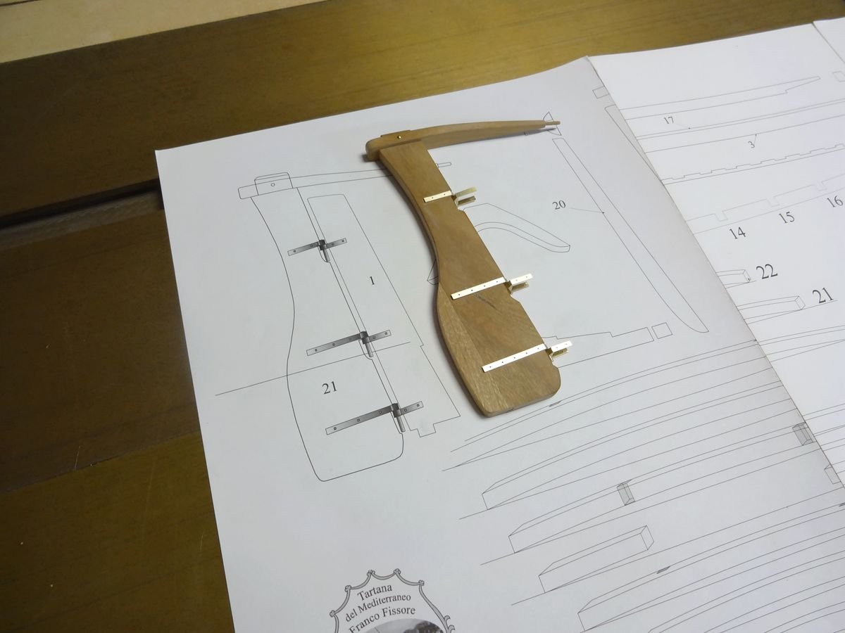
I think that hyw - unfortunately he didn`t tell us his name - built the winch strictly according to the drawing released by ANCRE.
So there`s got to be a different way to lock the gears to prevent the winch from spinning reverse.
A gear that`s shaped like a circular saw blade with a pawl, that engages at the steep side of rhe teeth, is self-locking indeed.
But I think that self-locking of the winch on this particular ship is obtained in a different way.
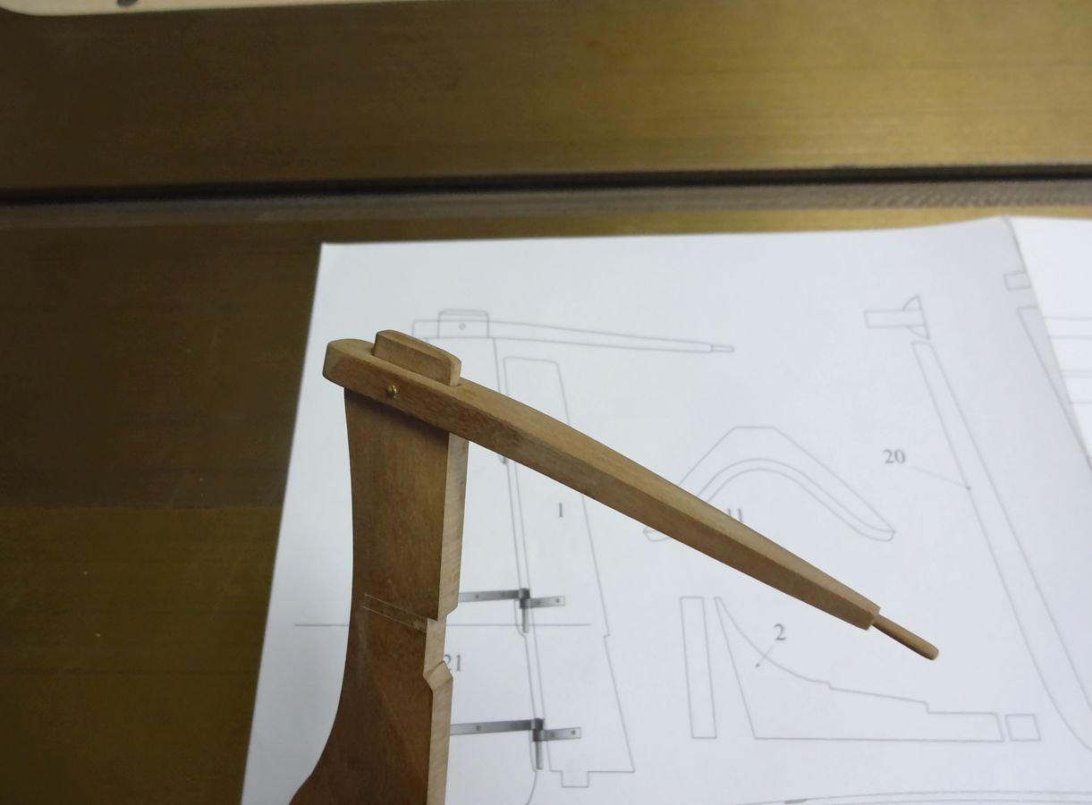
Moving the long two-sided lever seems to spin the winch. Perhaps friction prevents it from spinning reverse.
E.g. you turn a rotary table by turning it`s worm gear. But you can`t turn the worm gear by turning the table.
It`s self-locking without a pawl to be engaged.
Michael
Marvellous work on Gemma.
Although I made the locking mechanism according to the drawings, I did misinterpret the shape of the gears.
- druxey, EricWilliamMarshall, mtaylor and 1 other
-
4


Rectangular positioner
in Modeling tools and Workshop Equipment
Posted
Hello. The pursuit of better is my model not to give up the concept. I have developed or copied and improved things without selling a lot of assistive tools. After all, I have been doing this for more than 20 years. I wouldn't go to a manufacturer for these things, because mass produced things aren't guaranteed, and only the designer can understand the parts of the structure that need to be precisely controlled.