


Mirabell61
-
Posts
7,401 -
Joined
-
Last visited
Content Type
Profiles
Forums
Gallery
Events
Posts posted by Mirabell61
-
-
Hi Levebvre,
the display capacity in my hobby office is exhausted for a longer time ago already. Because I favor a glas-casing for permanent dust protection, it takes even more space every time.
Three ships have now already moved to our attic room office for this reason. My wife does not like shipmodels in the living areas of our home, and I have accepted that wish., so the lightship is probably the last one built in my shipyard. Perhaps there comes an oppertunity for selling the one or other some day for a fair price.
Nils
- Jack12477, Retired guy, Canute and 4 others
-
 7
7
-
Thank you Lefebvre,
as I`m retired from my profession many years already, I have much time for my hobby. I guess its appr. 15-20 hours per week, but my admiral keeps me going also for house and garden.
Nils
- Canute, mtaylor, FriedClams and 2 others
-
5
-
Hi and thank you Gary,
many of the sequences have been performed with my previos models before, so I don`t have to spend too much time and headachs in thinking of how I shall do it.
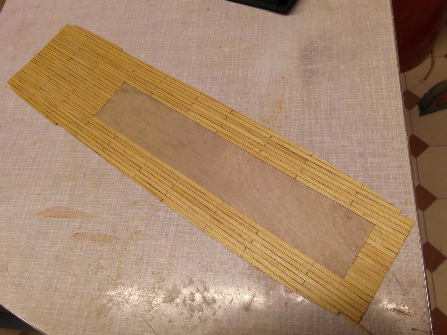
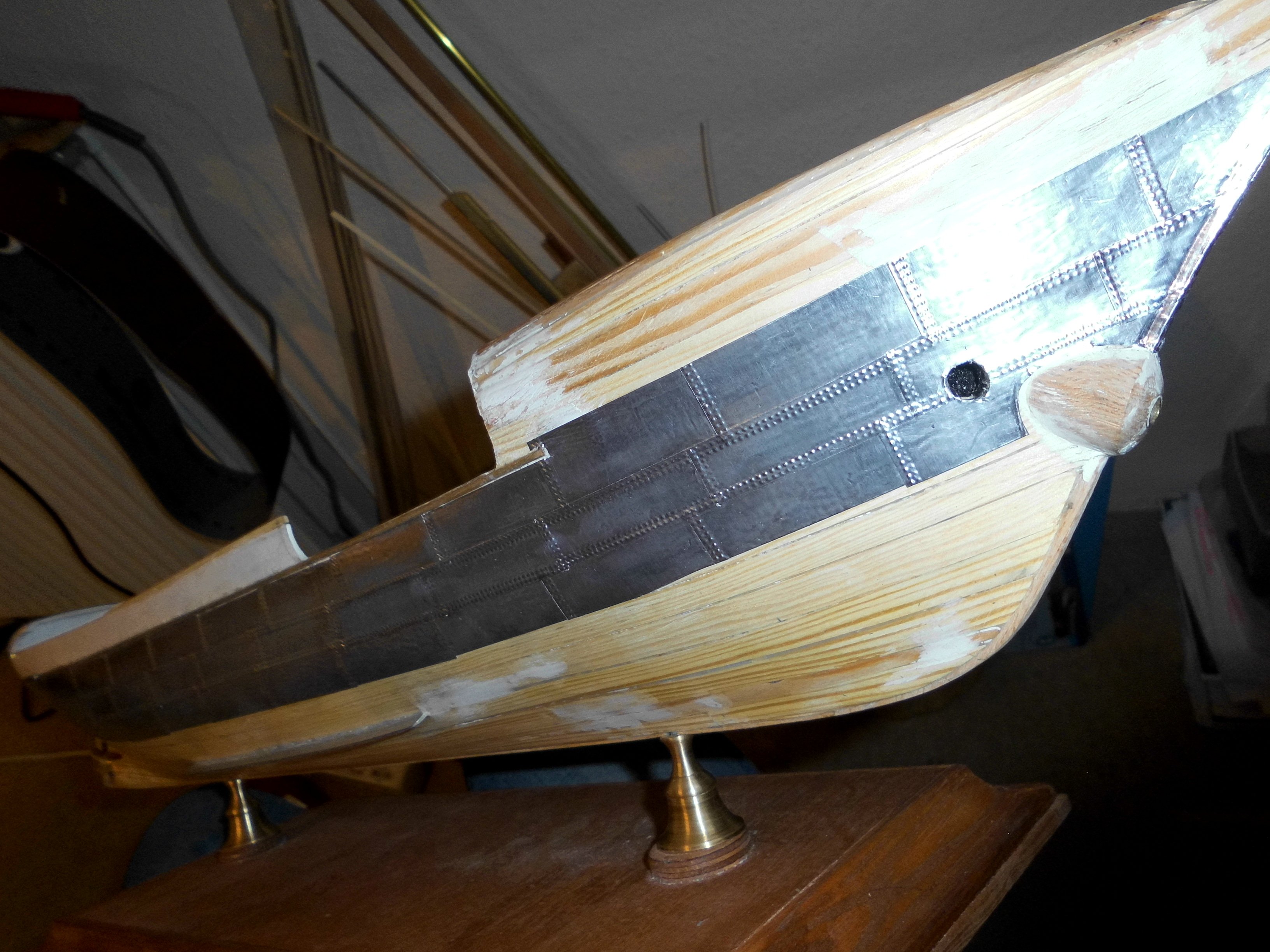
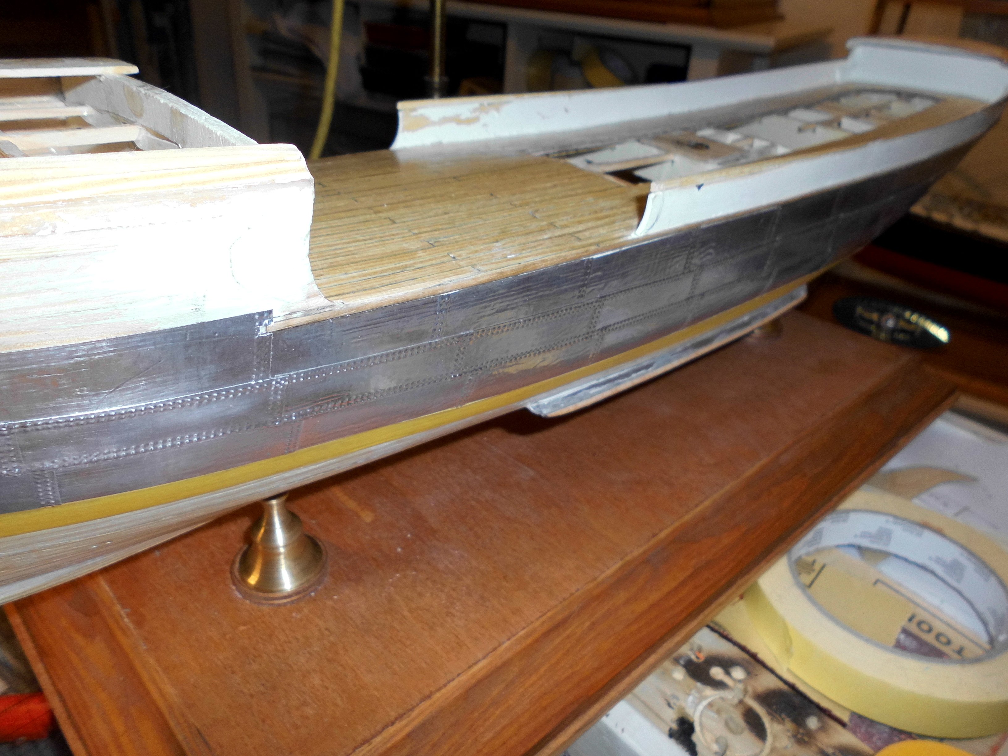
Here for example, I started with the plating today.
New this time is the use of 10 mm wide Tamiya masking tape as a space holder, as I`m plating in "Belts" and need the better steady horizontal line for optical appeal
The plates are cut from a self adhesive aluminium foil roll with a table paper guilutine. Poncing is done with a suitable double tooth wheel ( clock cock wheels) to the back of the protection paper before removing it.
The foil thickness (without glue film) is 0,125 mm for best results
Nils

starting with the trick part
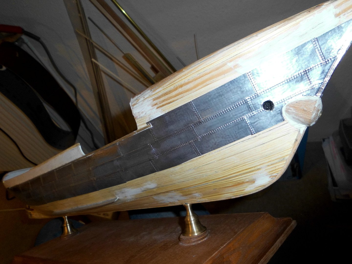
in Basic the plates are 15 x 50 mm, The rows, apart by 10mm, and then a cover plating "belt" over the 10 mm wide horizontal gap. The platings are stagered to the next line above.

a nice smooth hull surface provides a good ground for plating on
10 mm Tamiya distance holder, removed again before the covering, overlapping "belt is put on
-
exellent work Simon,
She`ll be a beauty, once she`s finished
Nils
-
many thanks Richard and John,
Richard, the lightmast, still to be finished, was not so easy as I had thought .....
John, I`ll do my best for the further build ....
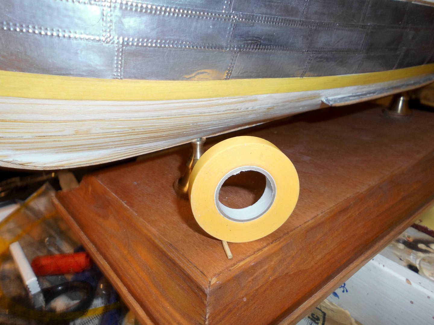
Yesterday I made a first dummy trial for painting, plating, attaching of an obsolete 20 mm high letter. The bright light red color is RAL 2026 in silk-gloss, that is the one used on german fire-brigade and civil rescue vehicles.
Nils
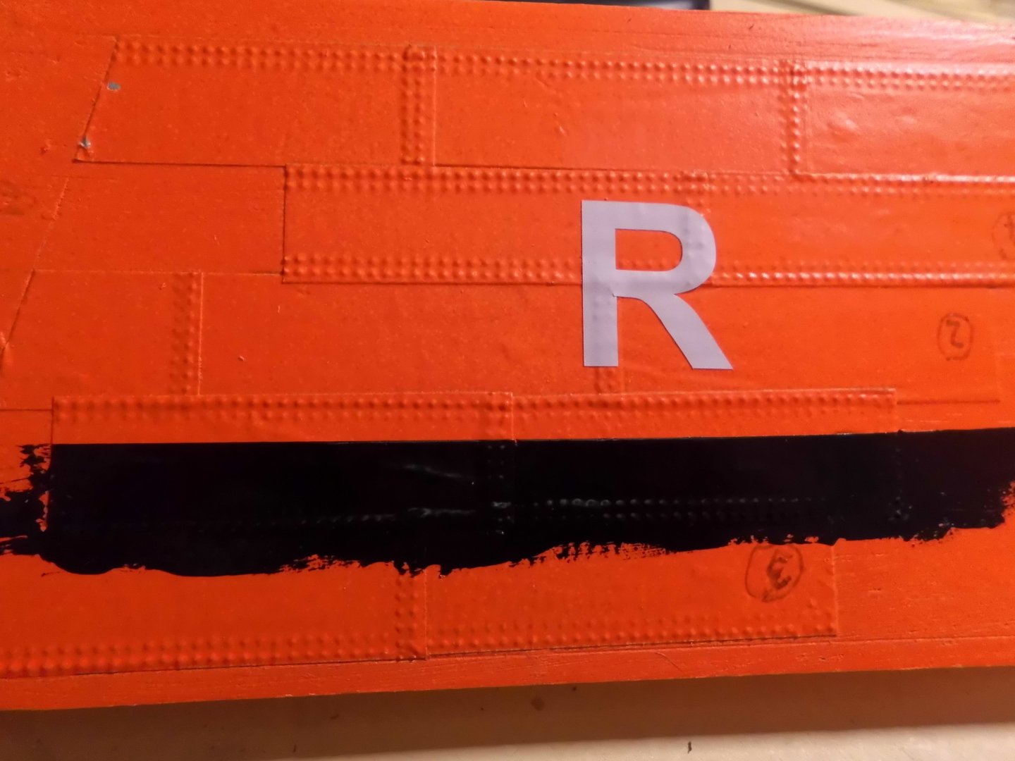
I am a bit suspicious about the permanent sticking quality of the letters on a structured plating background. In the moment it seems to work ....
The black sub waterline color is a silicone based black thermo-coating paint used for oventubes, etc.
- FriedClams, Jack12477, yvesvidal and 9 others
-
12
-
amazing work Ian,
well done !
Nils
- mtaylor, Keith Black, Glen McGuire and 1 other
-
3
-
 1
1
-
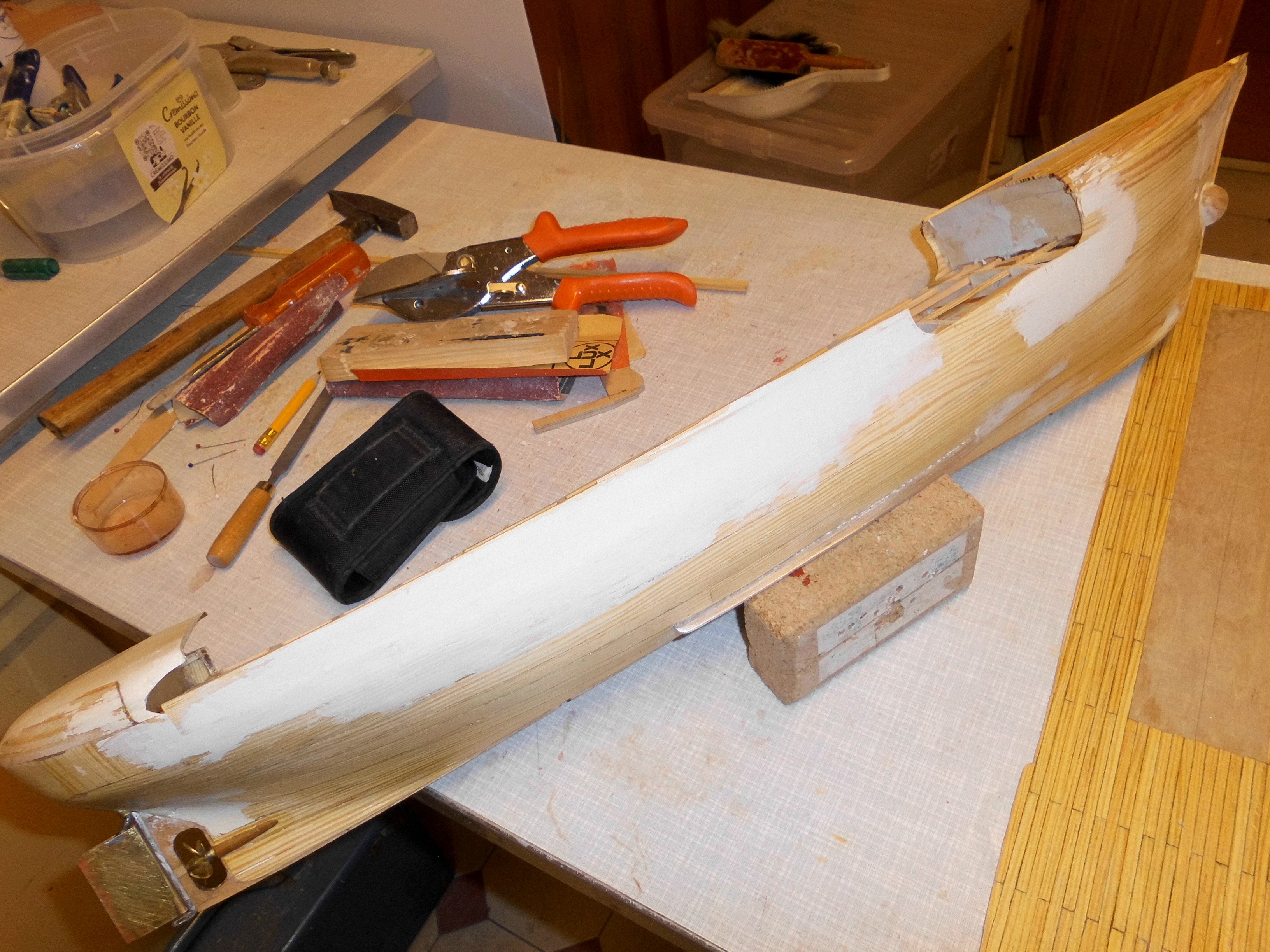
Update
Hull is all smoothened out and aft rounding rails (brass halfround) are mounted. The other rails will be from halfround nutwood strips.
All is ready for metal plating now. Am preparing for railings, starting with forecastle deck. First dry fit for foremast and lightmasttower
Nils

rounding rails fitted. These are bent to shape, so that there is hardly no stress for springback when glueing on, also to avoid messing with the glue (CA)
a bit of wood filler will do to smoothen curves

masts in dryfit

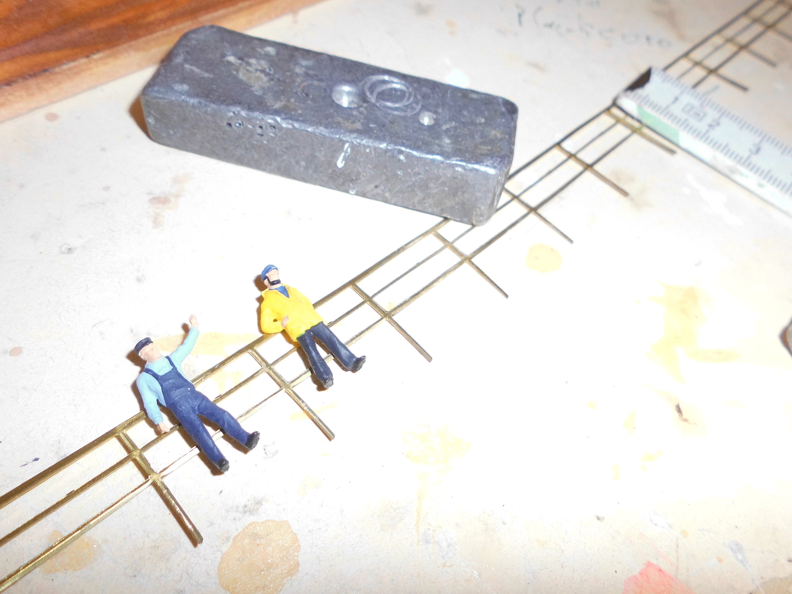
checking railing hight, the railing for the forecastle is a special bit ( 400mm length ) I found on the web, as the last available piece. It is of chemical etching and the brass has 0,6mm thickness, that appr. twice the thickness as I used on my Ergenstrasse rails. Unfortunately the source company does not exist any more, what a pitty. This railing type can be inserted into prior drilled holes of 0,8mm diam, and the hight of the top line therefore adjusted to the required hight, I will solder on mini washers as stopper on to the fastening posts, so that the chosen hight can be permanently fixed for 1:87 H0 figurines after glueing in.
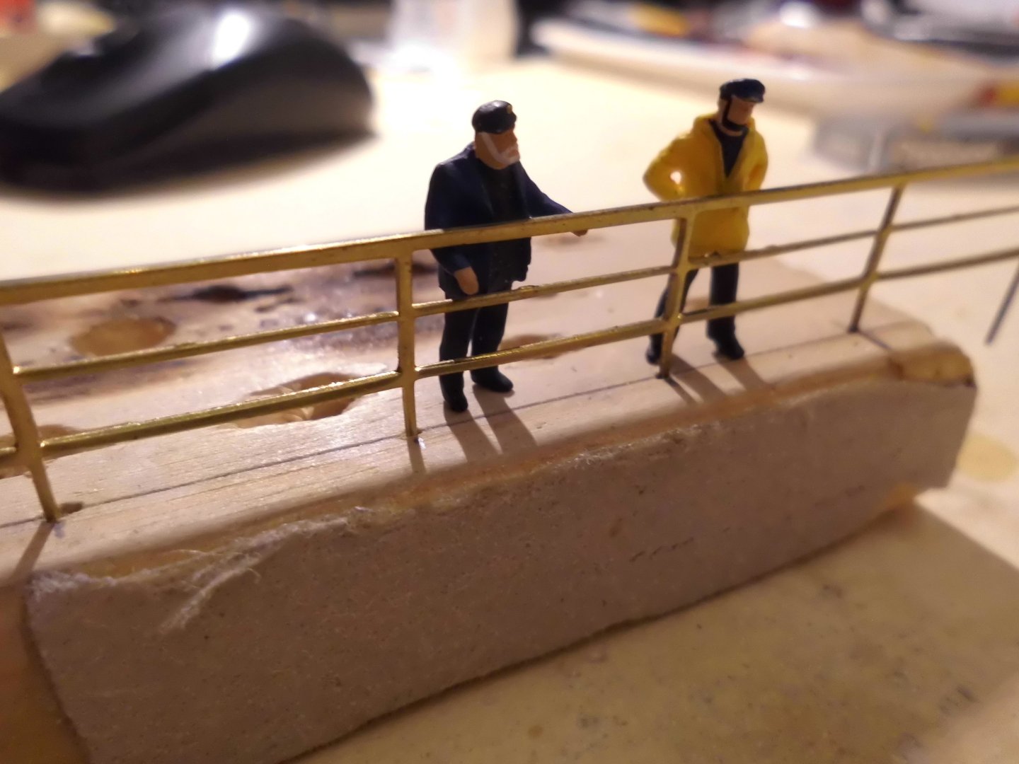
I wish I could get more of this railing type Here a dummy with the desired hight

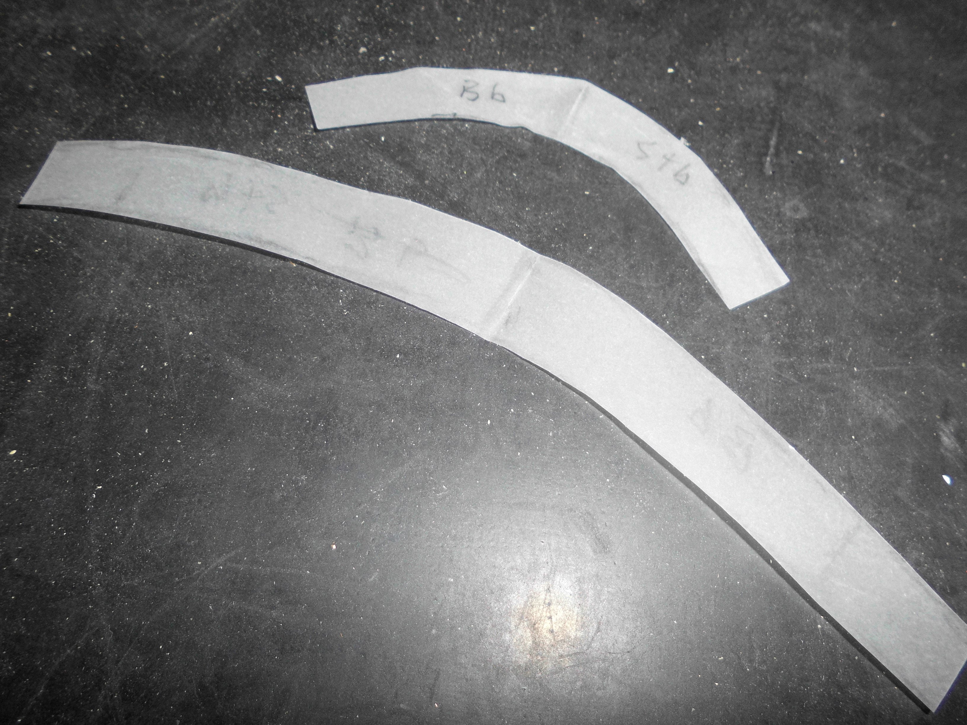
here are the fist two templates for the aft round metal plating
-
beautiful work Siggi,
lovely fitting out of the panels
Nils
- FriedClams, Siggi52, Ian_Grant and 2 others
-
5
-
Exellent metal work at the heel Keith,
Nils
- FriedClams, mtaylor, Retired guy and 1 other
-
4
-
good planking and painting job Eyüp
Nils
-
Many thanks for looking in Vaddoc,
you`re always very welcome, and I hope you`ll stay tuned. The mushroom anchor is quite common for holding lightships to their position, having the nose in the wind, it prevents the ship from rolling too much for better convenience to the crew.
I like your 21`Fisherman`s Launch
Nils
- KeithAug, mtaylor, Retired guy and 4 others
-
7
-
Congratulations B.E. to your HMS Indefatigable,
It`s wunderbar !
Nils
- Blue Ensign and mtaylor
-
1
-
1
-
Thank you Keith,
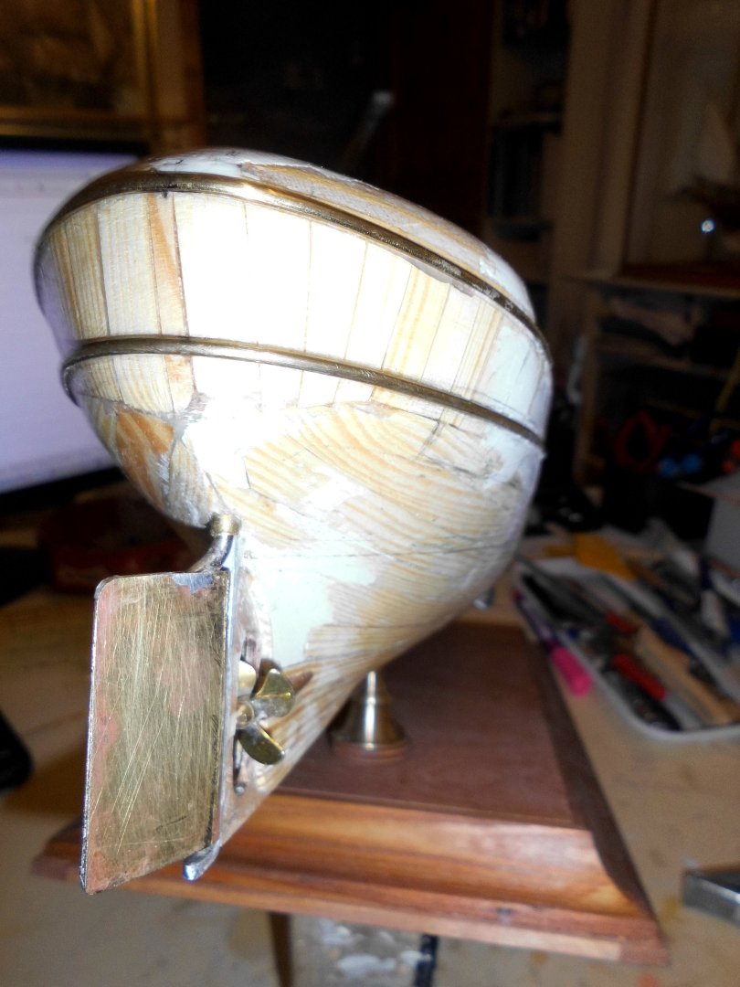
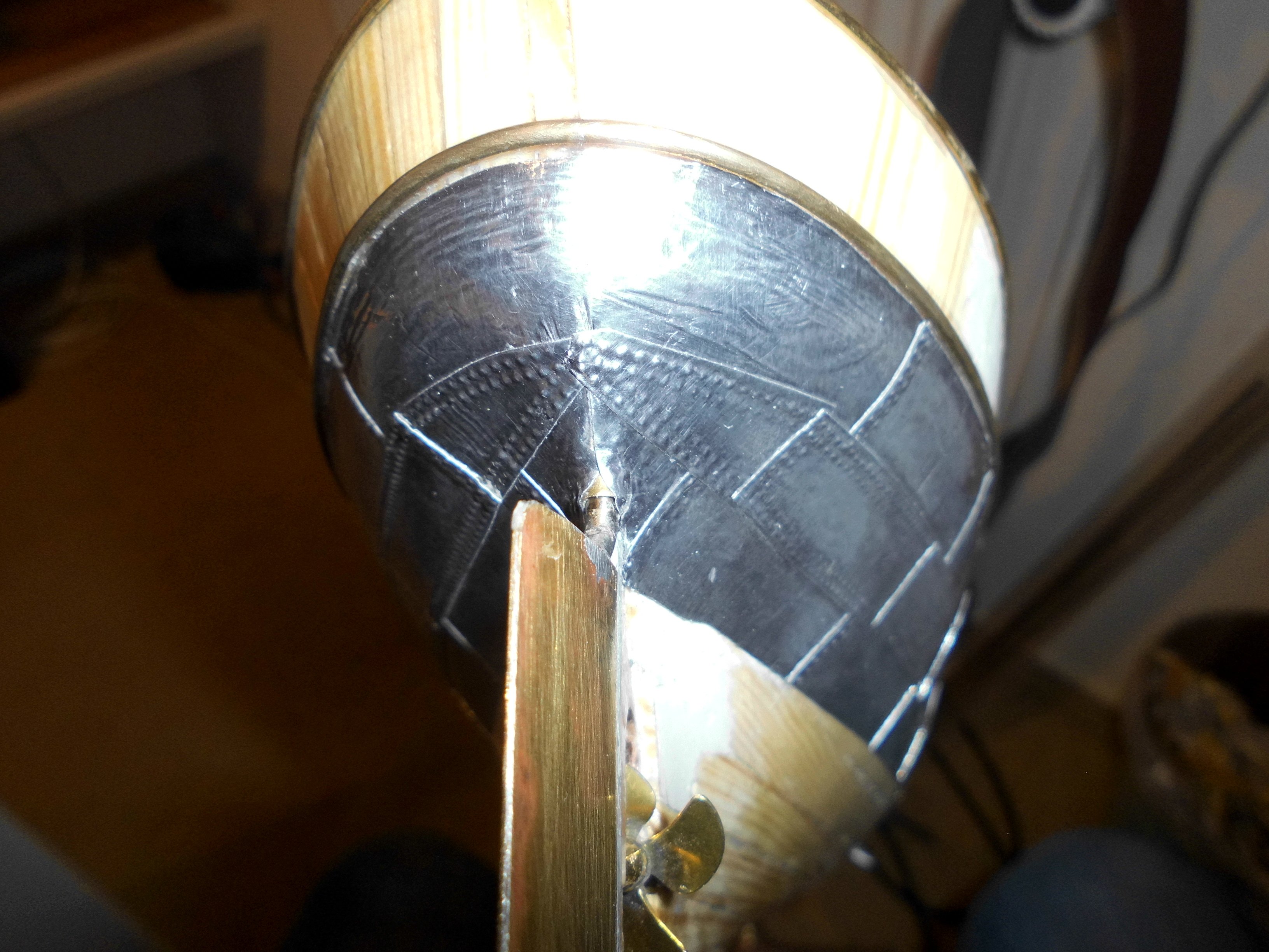
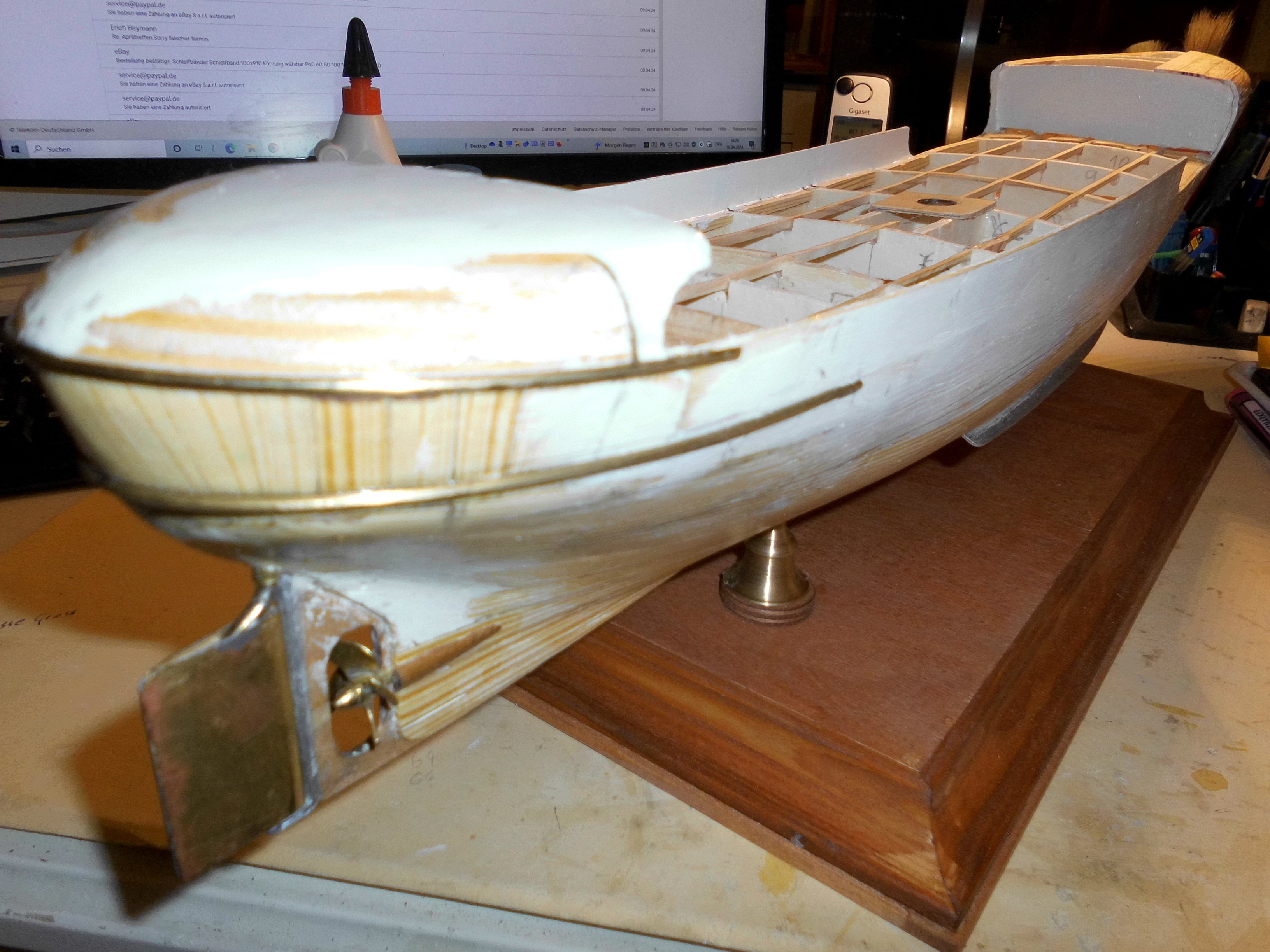
the Elbe 1 is equiped with an old U-boot diesel motor of 650 PS for propulsion. I fitted a 4-blade prop (like shown in the Plan, although I see a 3-Blade one in one of the dry dock pics. The 4-blade in 20 diam. brass with M3 hub looks better to my eyes.
Here a few details I made yesterday ......
Nils

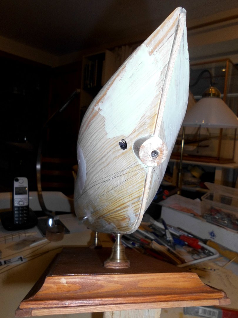
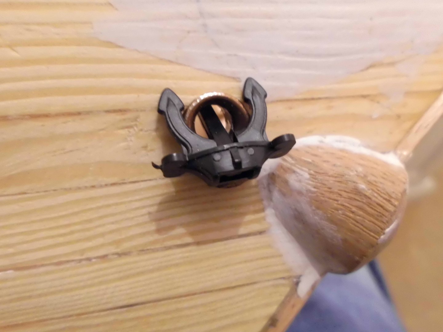
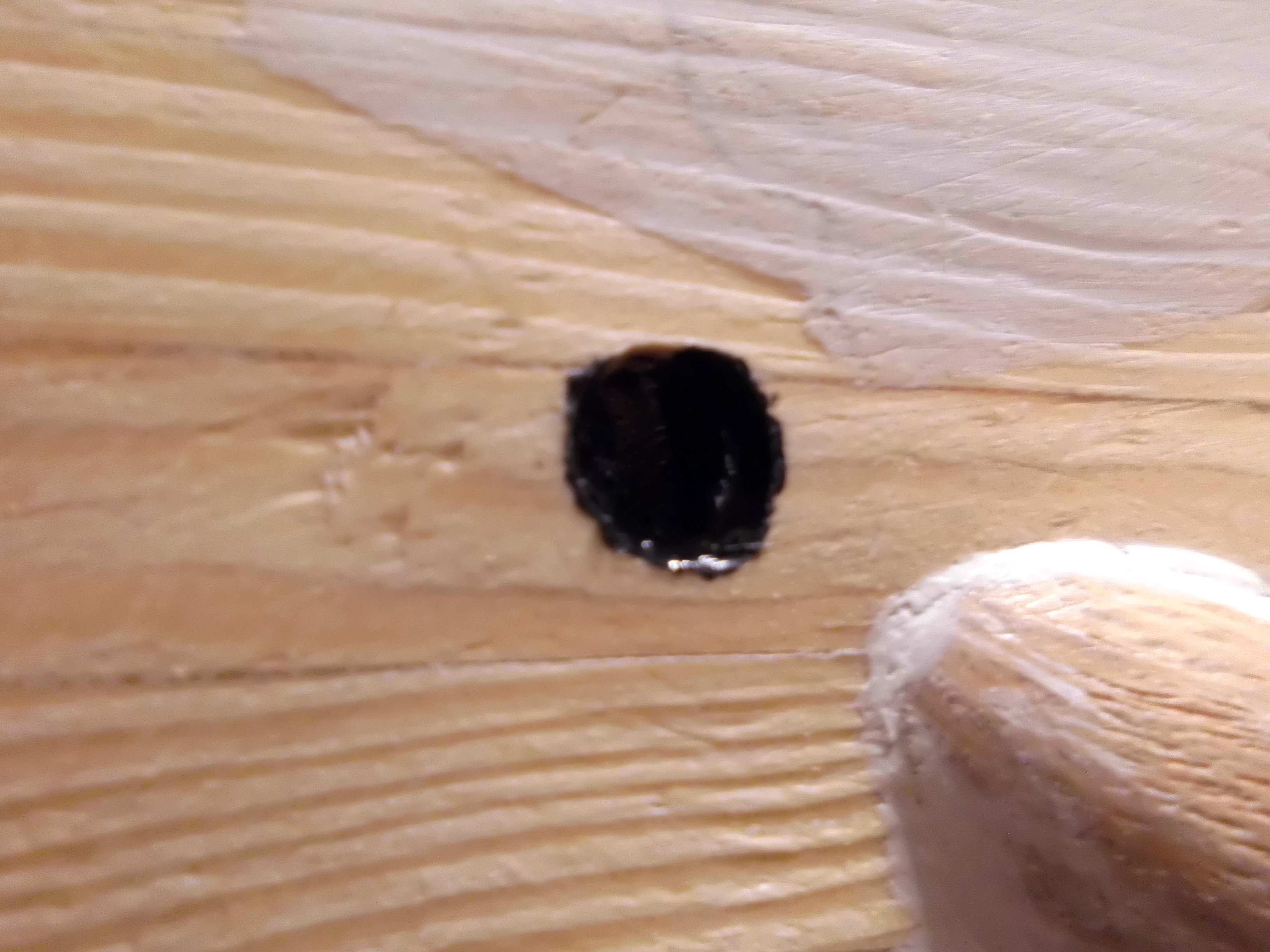
the stb. side anchorshaft

inside of the shaft blackened
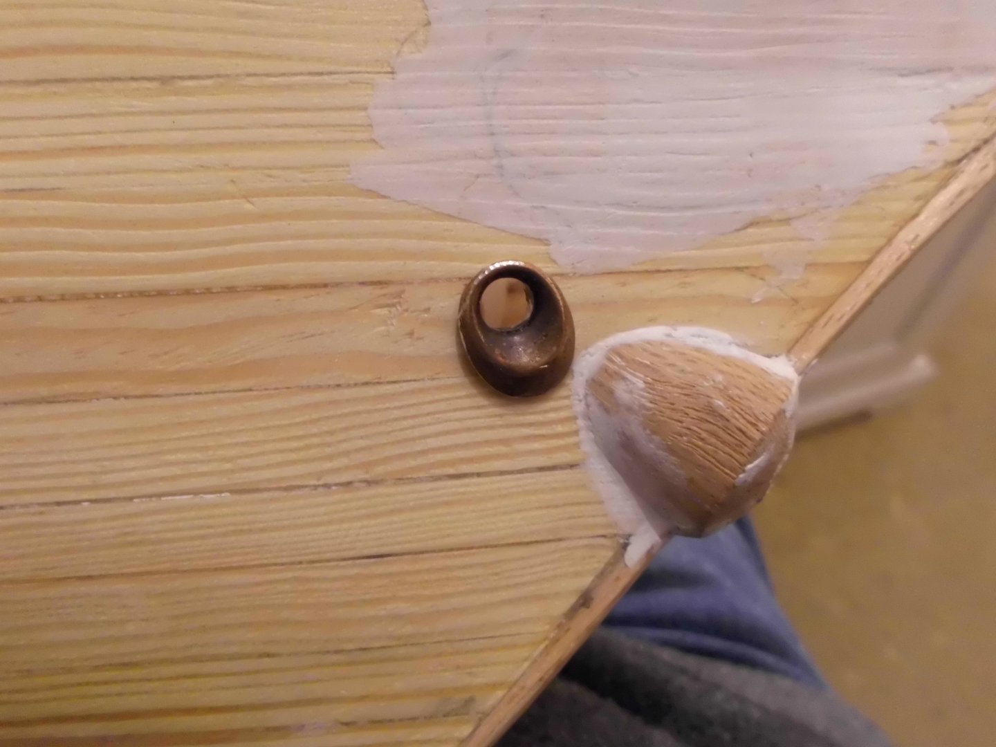
fitting of the anchor fairlead

anchor dryfit, (40 mm long anchor with with slip in shaft )
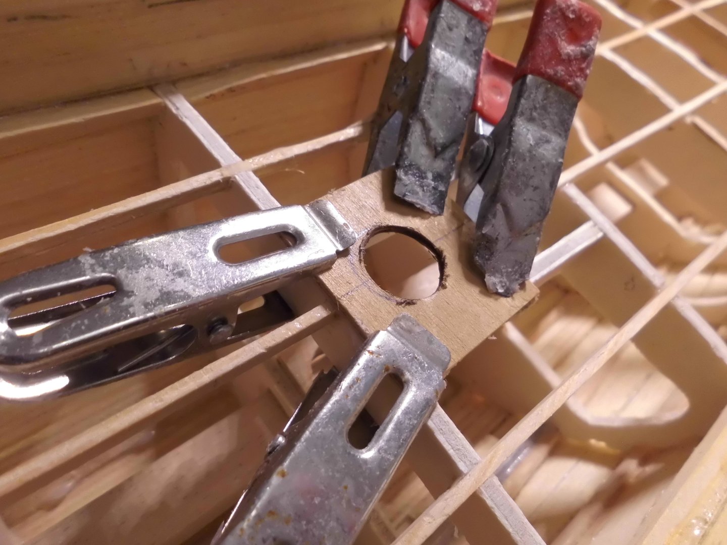
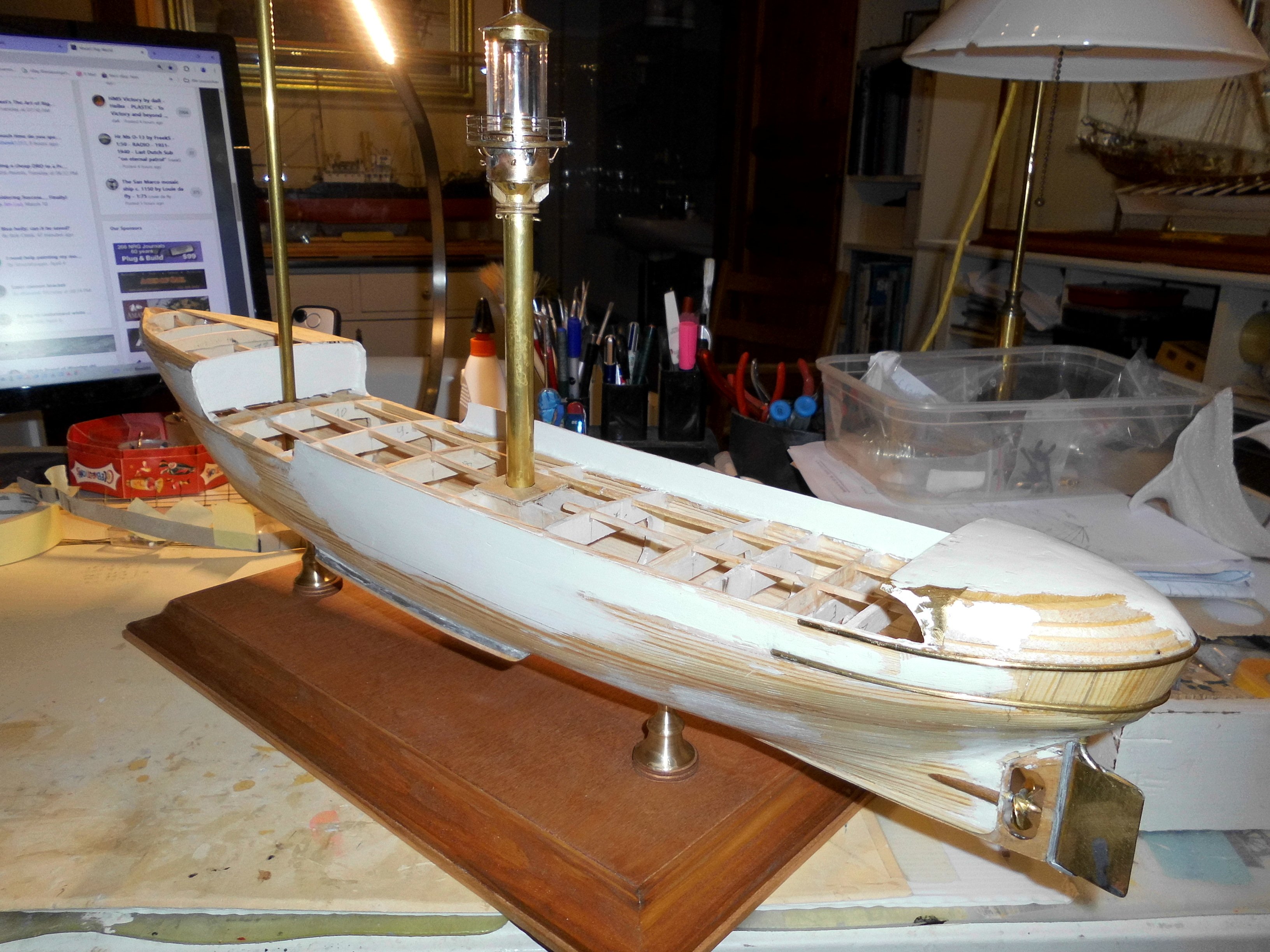
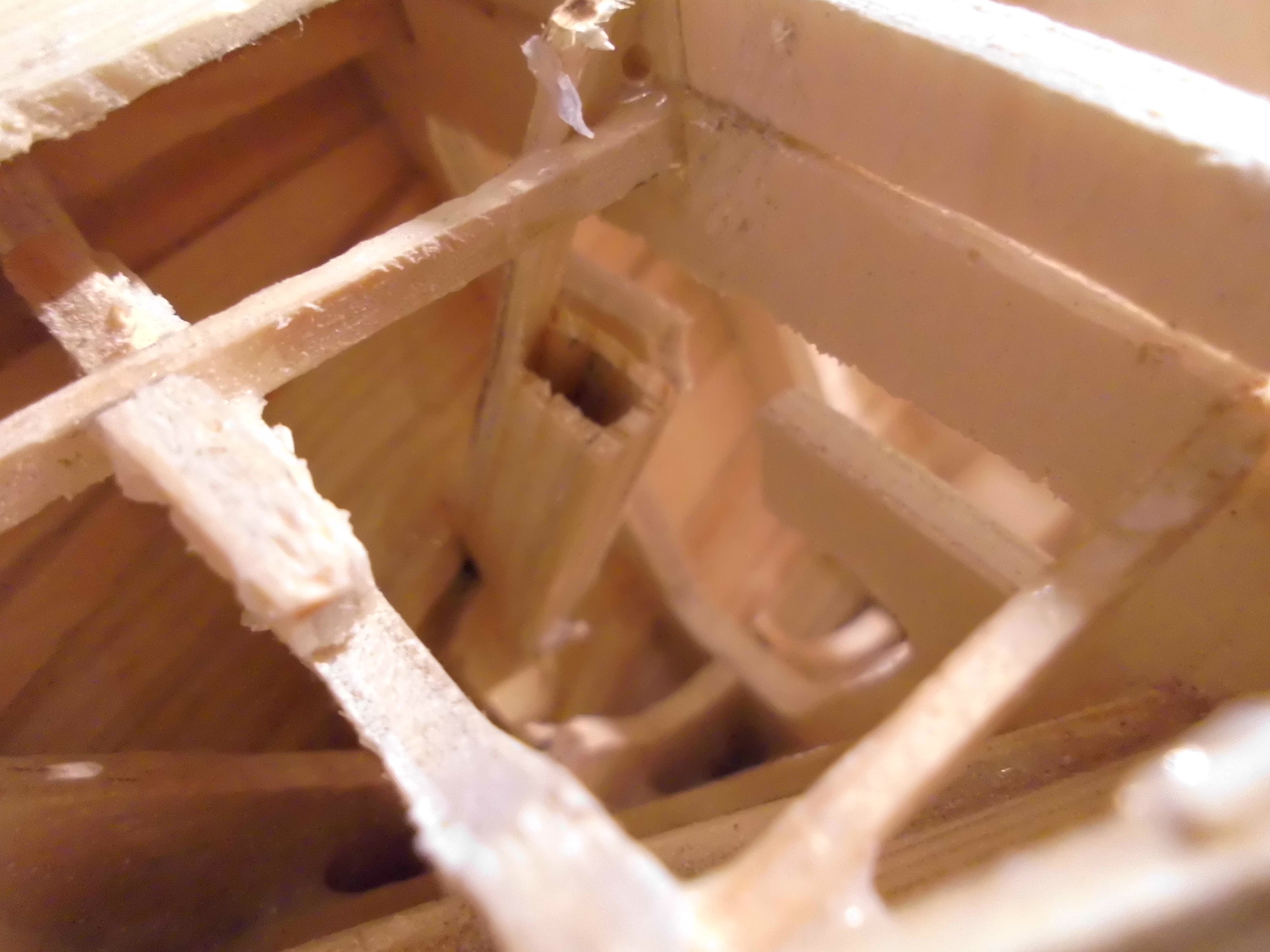
this is the deck- level support and guide for the 13mm tube of the lighttower. The lower 13mm socket is fixed to the squarebar obove the keel
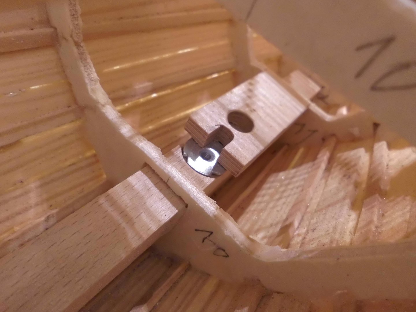
this takes up the lower socket for the foremast, the deck will also be equipped with a reinforcement at the point of going through. Here the stong "backbone" , (directly over the keel) which also takes uo the spindle press-in nuts can be seen
- Retired guy, mtaylor, Canute and 14 others
-
17
-
Update
Preliminary check :
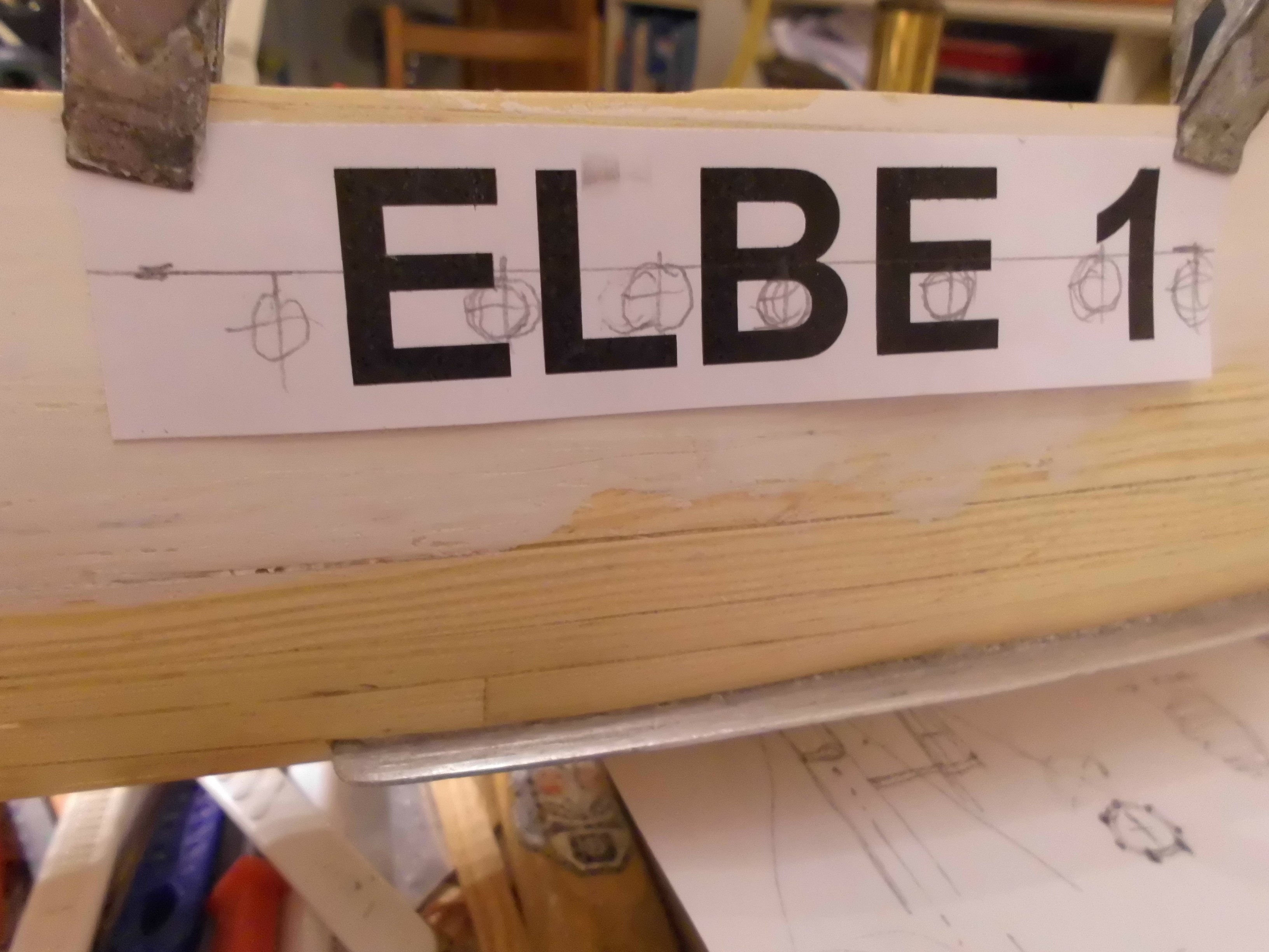
I made a black dummy for the white lettering on the later bright red hull. On the plan there are shown 20mm high letters. I will purchase them from very thin white selfadhesive foil.
There are three criteria to fulfill:
1) a halfround bumper rail on hight of the main deck will be horizontaly fitted to the hull, whereby the rail needs to run exactly on mid hight of the letters (letters E + B ), or slghtly below it.
Hopefully the foil of the letters will follow and remain sticking tight to the area around the rail without partially lifting off.
2) the horizontal line for the portholes, in adequate distance beneath the deckline, has to lay horizontaly exactly in the lower blanc spaces of letters E + B
3) the drill holes for the portholes have to be clear of the hulls frames in those areas (This also mirrored for the other side of the hull)
Nils

Dummy with 20mm high letters
The outside diameter of the silicone glassed brass portholes will be 6mm, these have to be fitted into the hull without cutting away the broadness of the lettering too much
-
many thanks Roel and John,
Roel,
I think you are right asuming that the mushroom anchor is not regularily hoisted.
John,
that was my thought also, but I remembered the dry dock pic proving me mistake ....
perhaps the constructors were not expecting "knots" in that chain causing possible chain break in stress situations
Nils
- FriedClams, FlyingFish, Jack12477 and 2 others
-
5
-
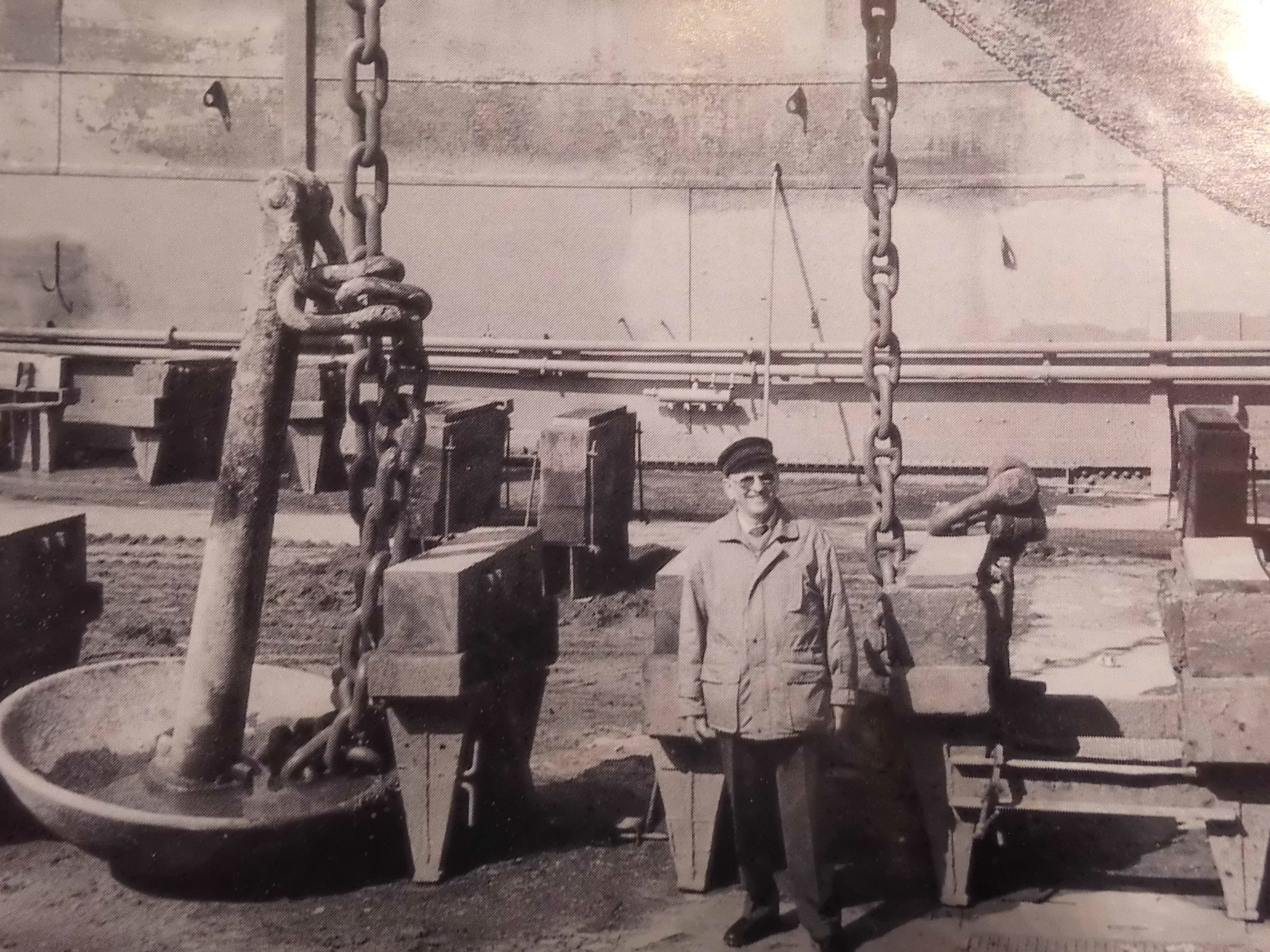
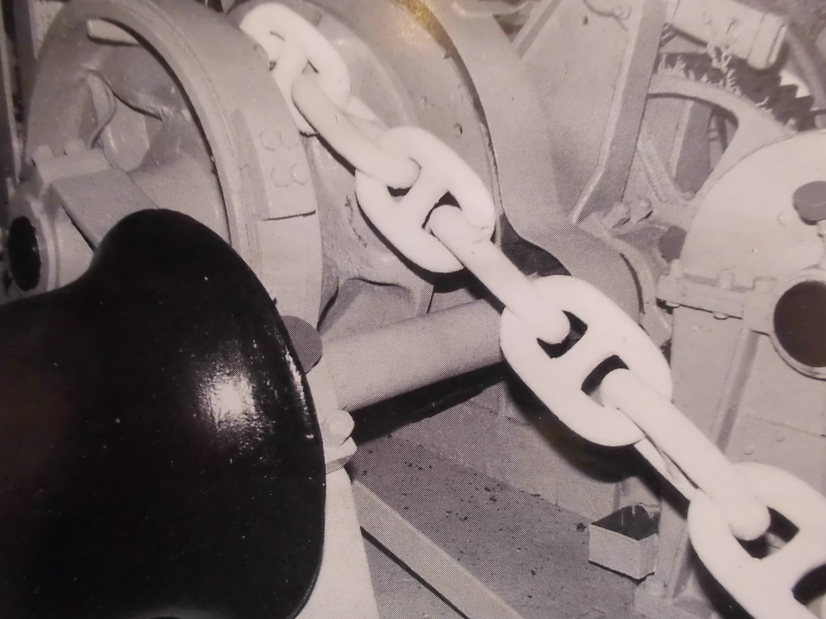
Many thanks for your comment input here Joachim,
and welcome to the build.
I looked up the version of the anchor chains when I got started. The mushroom anchor chain does not have these studs, but the stationary at the bow side Hall anchor indeed has a stud-chain.
Fortunately the autor (model builder Helmut Thomas) shot some photos of these details, in real in the dry dock, to be seen on the enlosed pics
Regards from Glinde to Westerwald
Nils
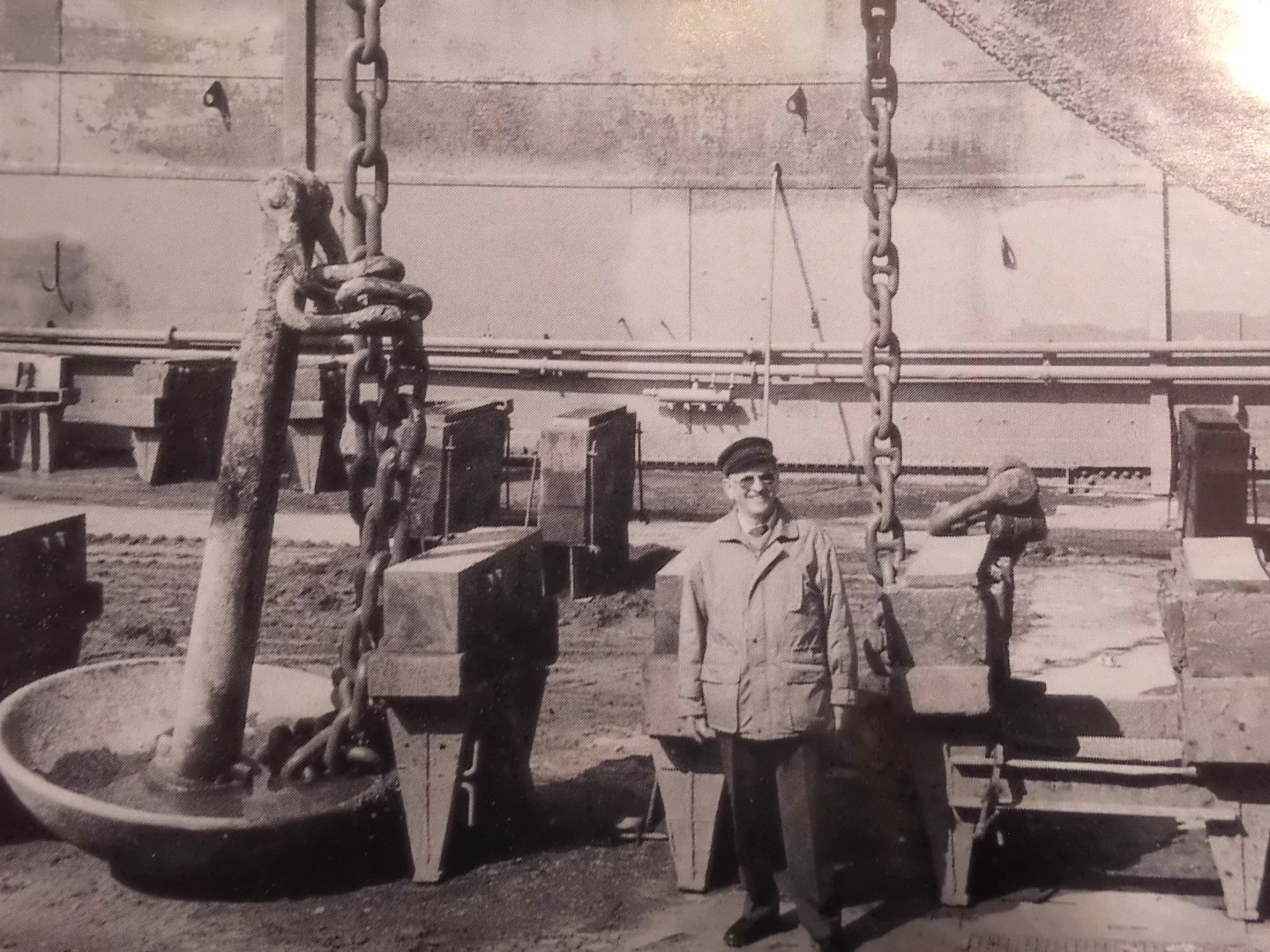
the lft side chain is the one for the mushroom anchor
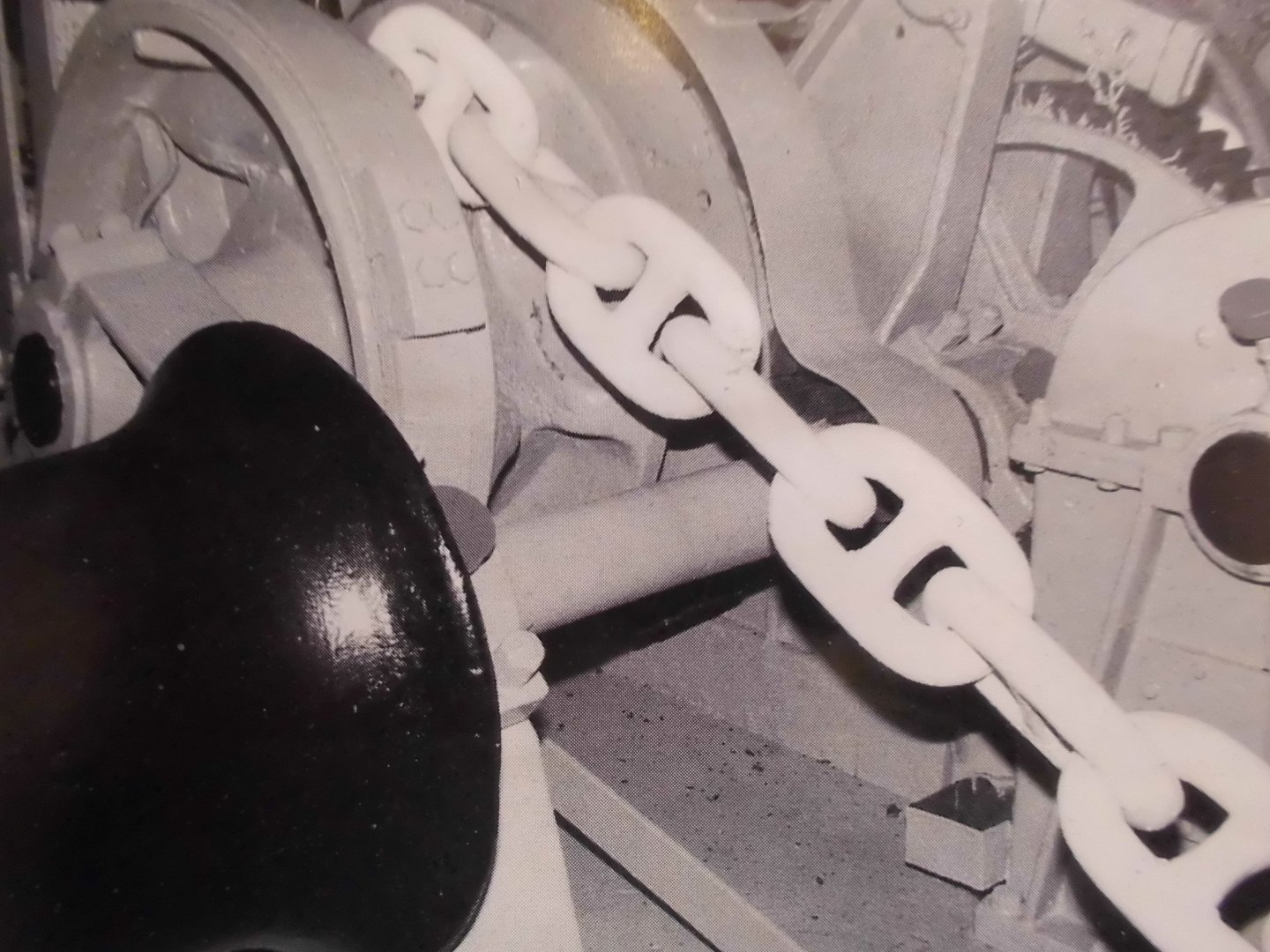
this is the chain for the sideHall-anchor
- FlyingFish, wefalck, Jack12477 and 8 others
-
11
-
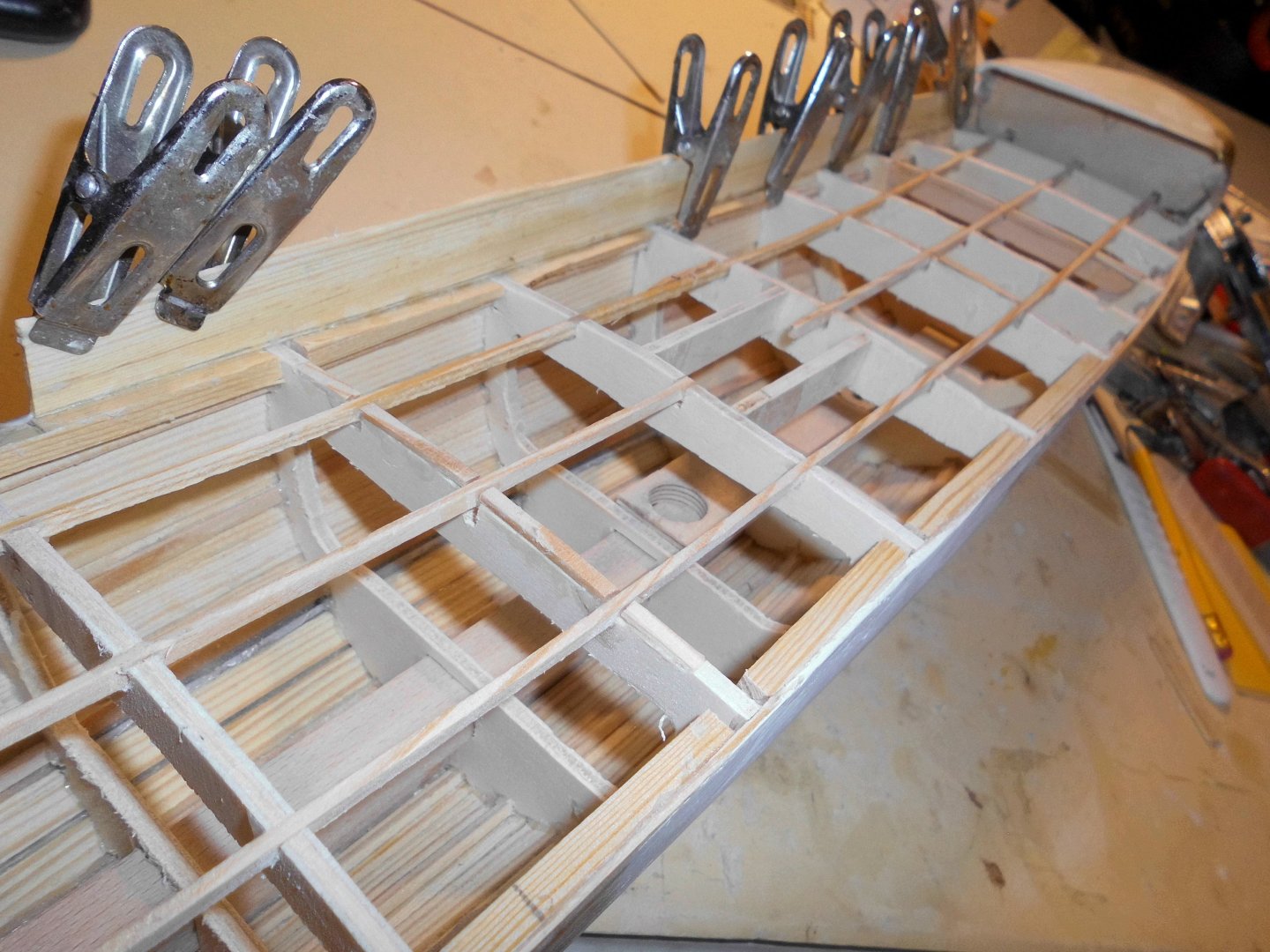
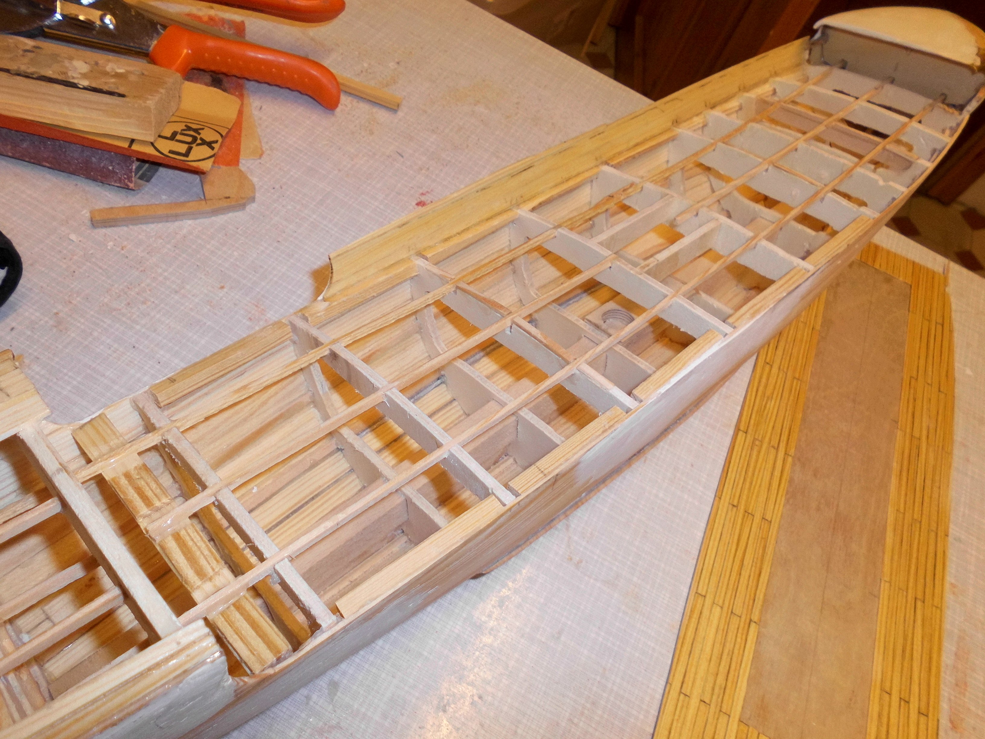
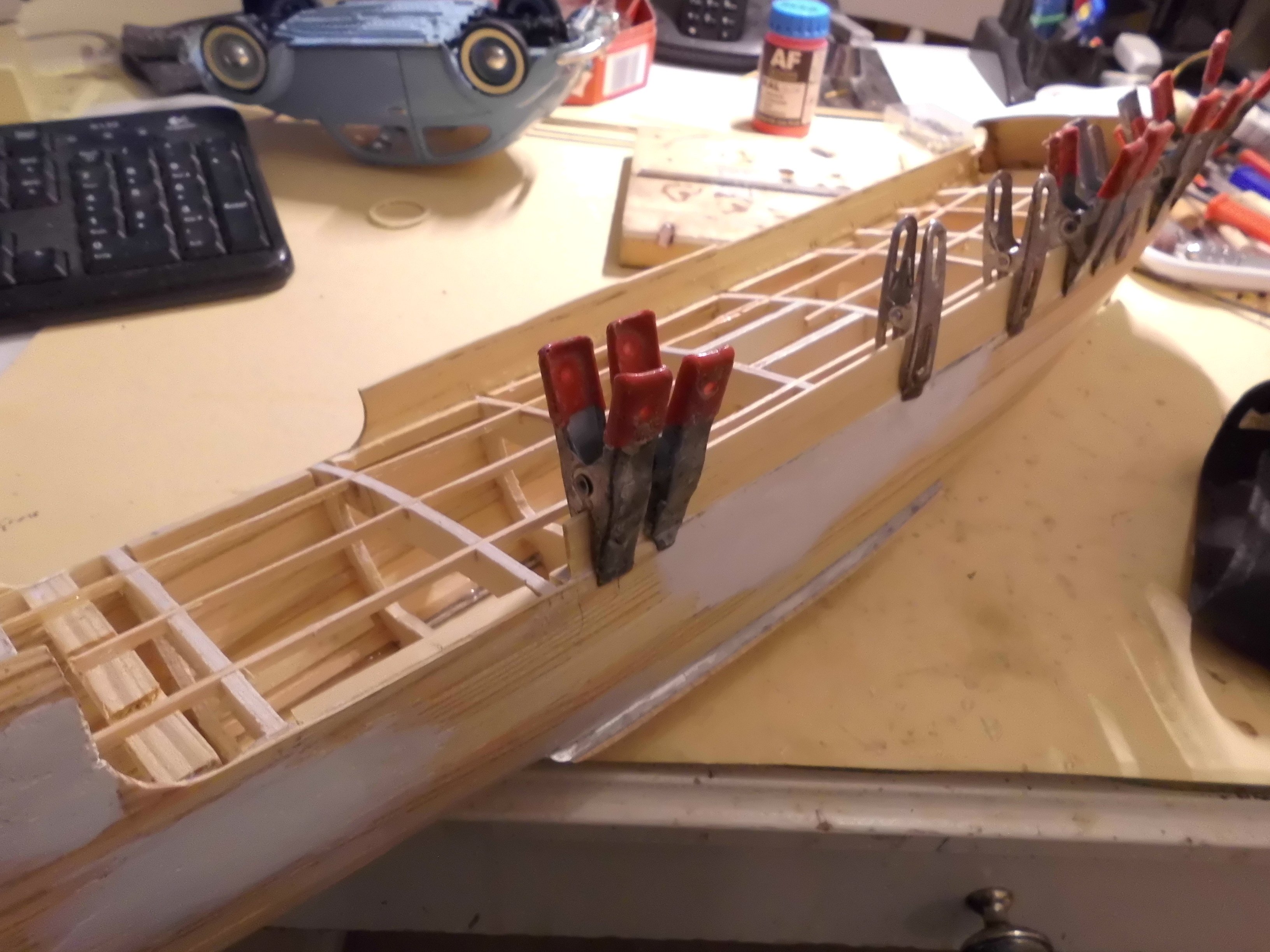
Update
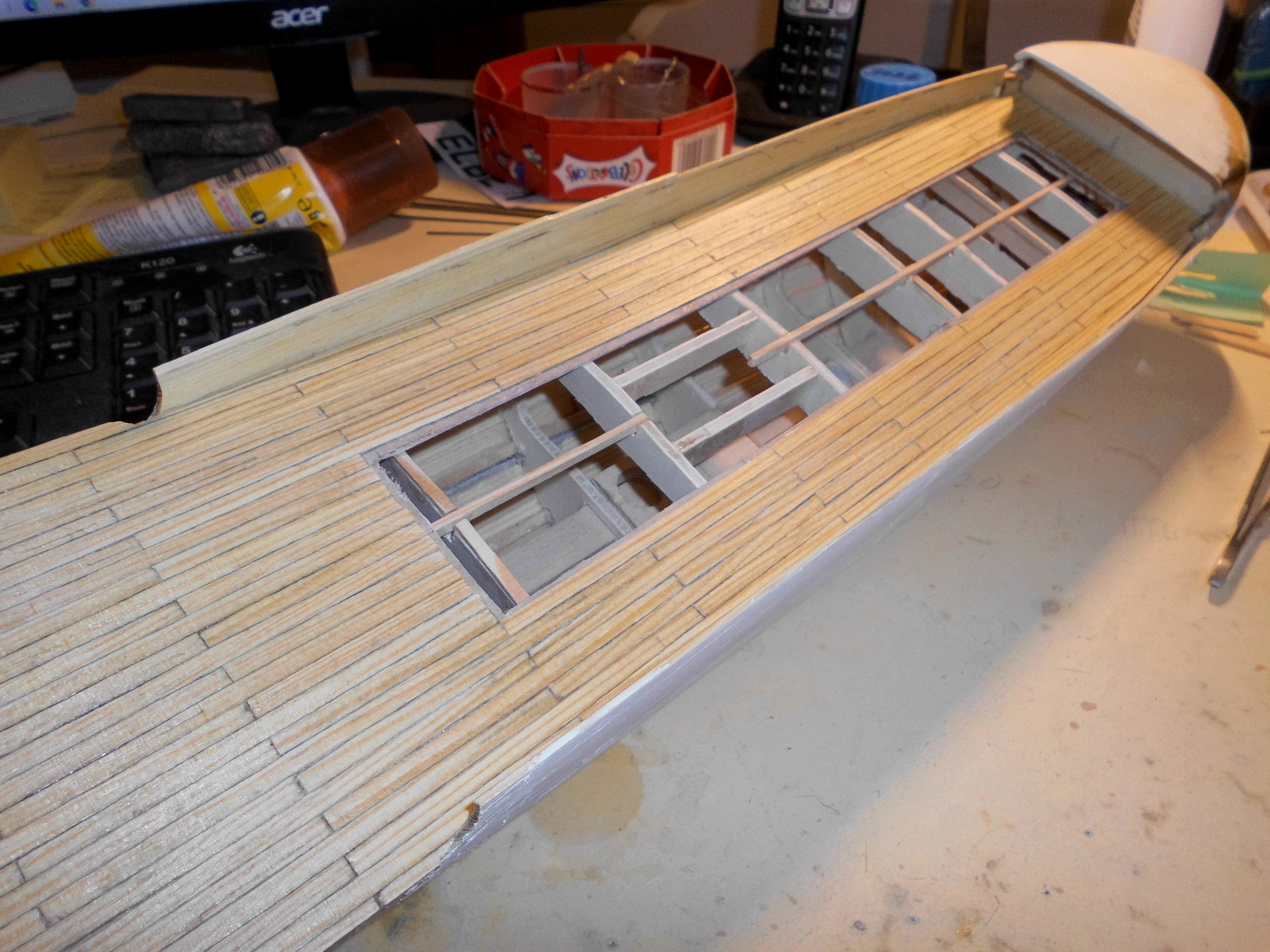
installed the anchor port fairlead into the forward side wall and fitted the operational Hall-anchor. also the bulwarks, the deck and fitting the deck in on the deck beams and between the bulwarks not permanently glued in yet, and the upper bulwark tops still have to be trimmed. I left an outcut in the deck for later access to the interior. The insides of the bulwarks and the vertical transverse frame (fore and aft) have to be painted before glueing in the deck
Nils

mushroom anchor brought out
stb. bulwark mounted

all deck beams checked for smooth deck fit
the planked deck

bulwark flush with upper side
operational Wall-anchor fitted

port side bulwark

deck neatly fitted in (dry fit) .
- Blue Ensign, Canute, Jack12477 and 12 others
-
15
-
thank you very much Greg,
I`m happy that my "Eagle of Algier" could be helpfull for inspiration with your build. You`ve realy created a wonderful model, so neatly built. In fact the Eagle is off the same Amati plan, only magnified to scale 1:48
I`m looking foreward to see your sails and rigging as well. Wishing you further success and much fun with your build you can be proud of.
Nils
- Greg Davis and catopower
-
1
-
1
-
very nice build Greg,
Nils
- Greg Davis and catopower
-
1
-
1
-
thank you John,
I have to install the anchors and their chain-tubes before I close the forecastle deck planking
Nils
- Retired guy, mtaylor, Canute and 1 other
-
4
-
very nice build Lars Peter,
Nils
-
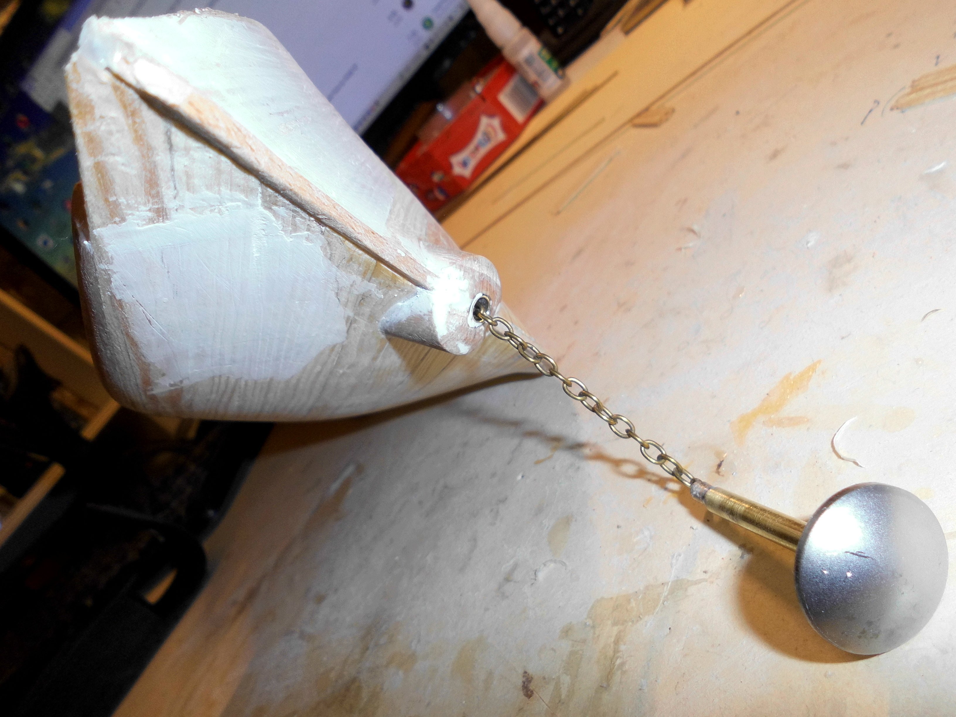
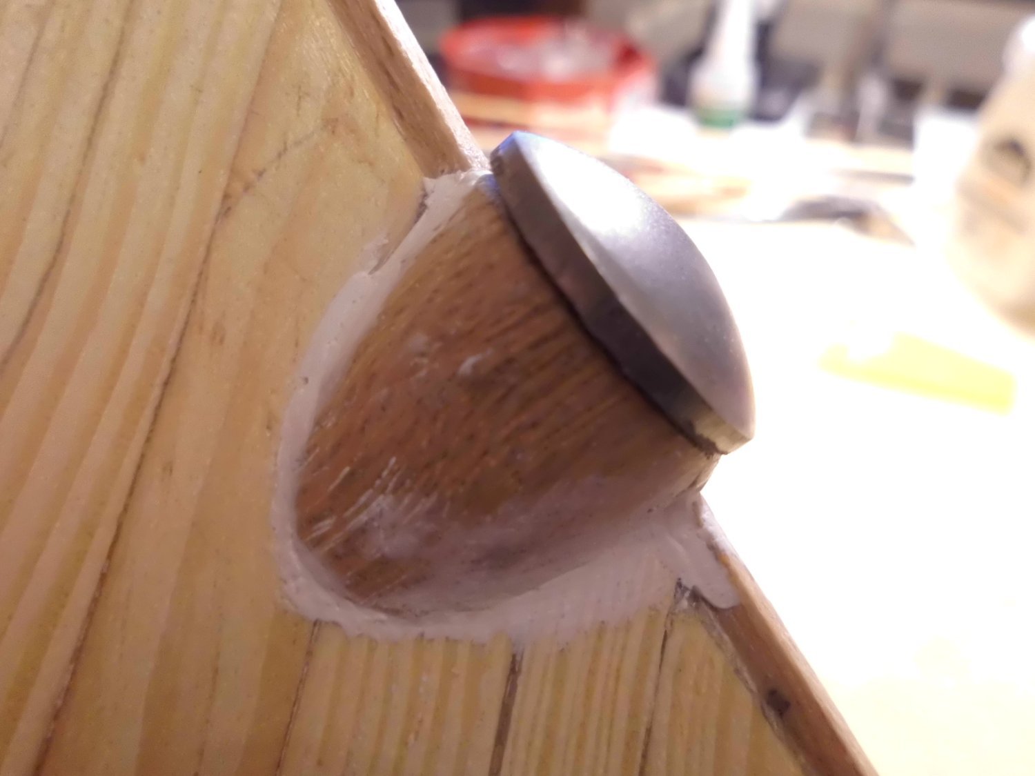
Updeate
made the mushroom anchor with chain today
Nils
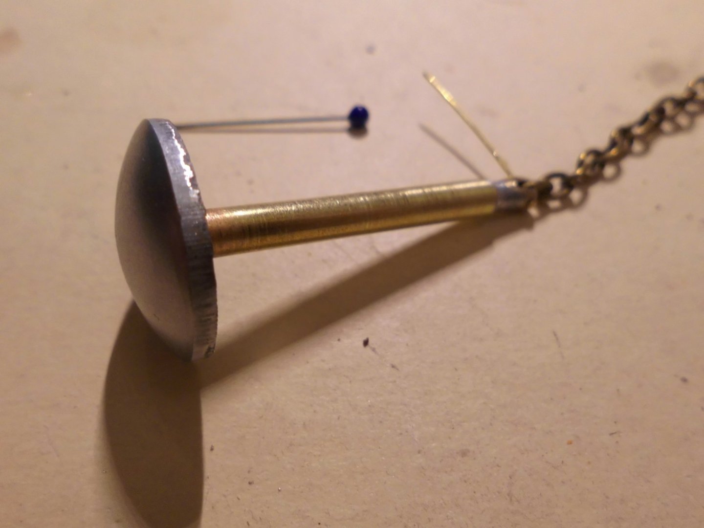
the size of a pin needle in the background

and against the pod
- KeithAug, FlyingFish, vaddoc and 11 others
-
14
-
thank you very much B.E.,
its nice to have such an appreciation from a master builder like you are,
Nils
- mtaylor, Blue Ensign and Canute
-
2
-
1
-


HMS Indefatigable 1794 by Blue Ensign - FINISHED - Vanguard Models - 1:64 scale
in - Kit build logs for subjects built from 1751 - 1800
Posted
a beautiful built launch B.E.
I also much like the tpo be painted figurines
Nils