


AnobiumPunctatum
-
Posts
1,267 -
Joined
-
Last visited
Content Type
Profiles
Forums
Gallery
Events
Posts posted by AnobiumPunctatum
-
-
On 4/30/2020 at 12:39 AM, catopower said:
TThe order for both wooden kits, the Wutender Hund and the new Kogge von Kampen, just shipped from Poland this morning. Not sure how long it will take to get to Ages of Sail, but they're on their way now. Probably be 3 or 4 weeks before they show up online.
The stern castle of the "Kogge von Kampen" is based on a shipwreck which was found in Kamen Netherlands. It's showing an older type of a stern castle. I am quite shure, that the rest of the kit is based on "Kogge von Bremen"
The cog "Wütender Hund" shows in my opinion the classic cog also with a stem castle. It's a generic cog model. Most historical pictures are showing the stem castle. There is always a discussion, of the Bremen cog was finished before they got lost, because she don't has this.
- ccoyle, popeye the sailor, mtaylor and 1 other
-
 4
4
-
If you choose the HMS Sphynx of a ship from this class, it is perhaps a good idea to go in contact with Alxander. He made excellent drawings of this ship.
- mtaylor, chris watton and dvm27
-
3
-
-
-
-
-
The cog is looking really nice.
- Chuck Seiler, Louie da fly and mtaylor
-
3
-
-
Wonderful Jorge. There are not so many Tritons, which already have reached this point.
- mtaylor, Kevin and Jorge Diaz O
-
3
-
-
-
After finishing the ensemble I got the information that the step between stem and knee of the head doesn't exist. There is a drawing in Steel's Naval Architecture, that shows this detail. I am missing this book in my library and follwed the design which David descirbes in the Swan Class series by my first attempt.
Now I've reworked the comstruction:
-
Your section is looking fantastic
- Ainars Apalais, Lynn Young and mtaylor
-
3
-
Congratulations Karl for finishing this beautyful model.
- mtaylor, Retired guy and Jeronimo
-
3
-
-
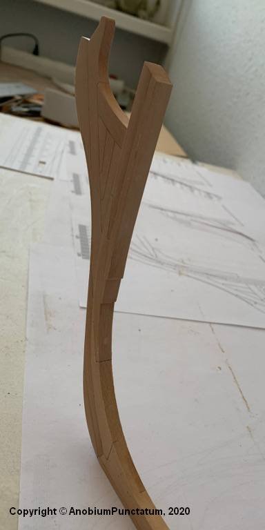
Actually, the weather is too nice to work in the shipyard...
...but a little bit I did manage to do this weekend.
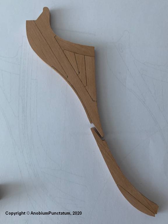
The two prepared parts of the "Knee of the Head" were carefully fitted to the steven and then glued together.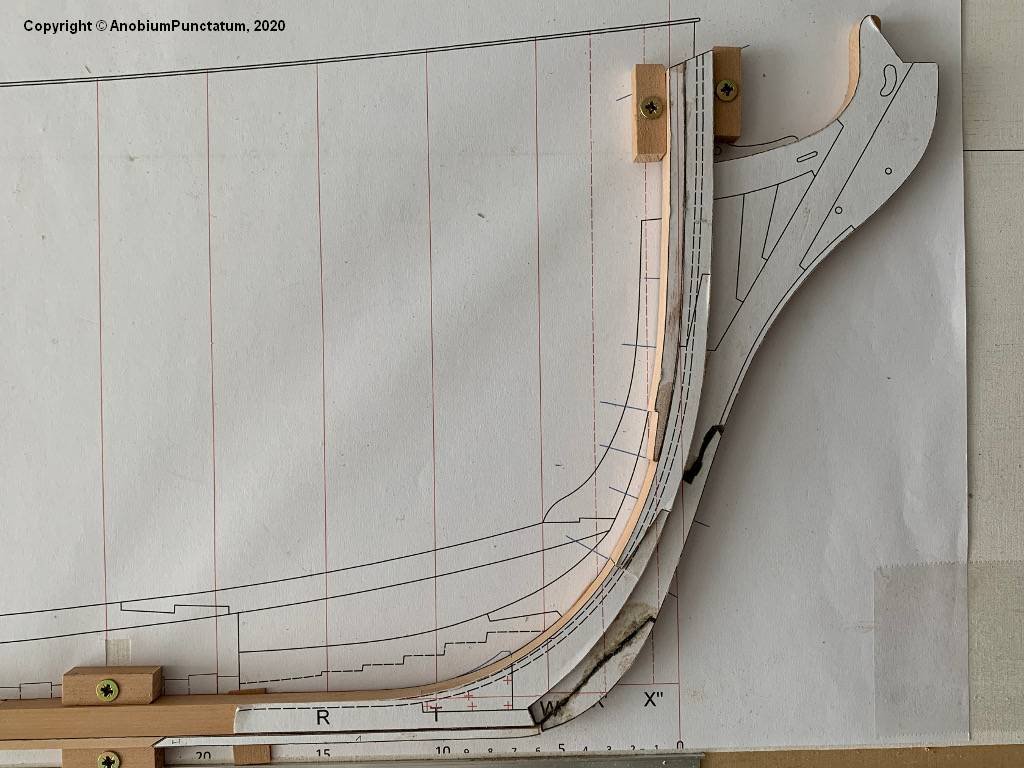
Next, all templates were carefully removed and the fit was checked again.
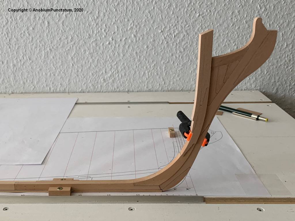
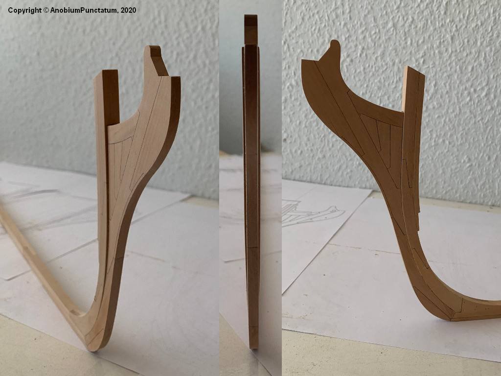
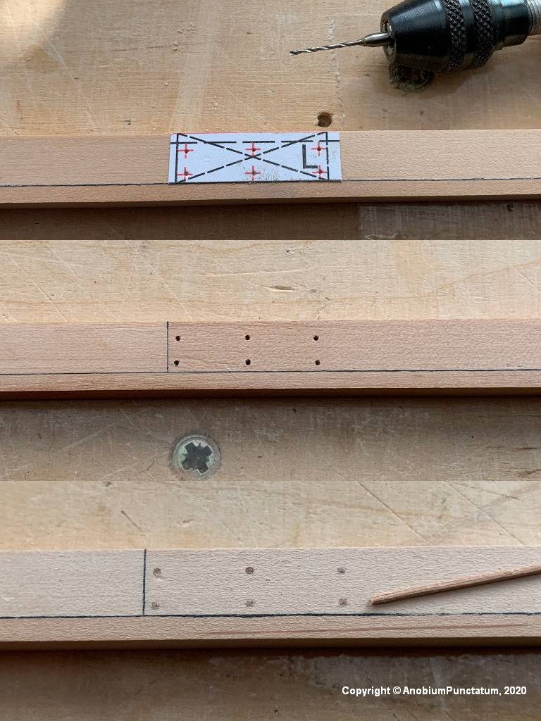
To make it easier for me to glue the Knee of the Head to the stem I drilled three holes of 2.0mm and fixed the component with brass wire. At this step the fit was checked one last time and some slight corrections were made.
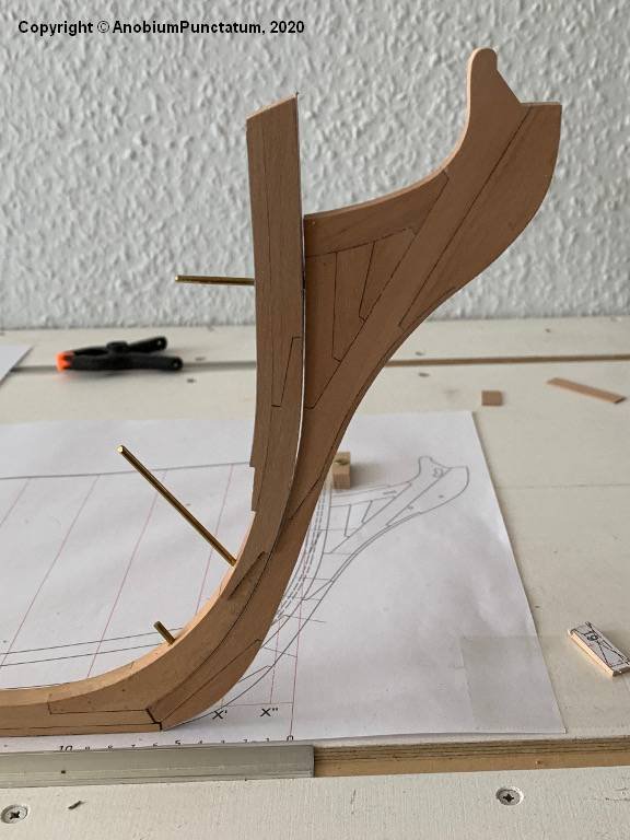
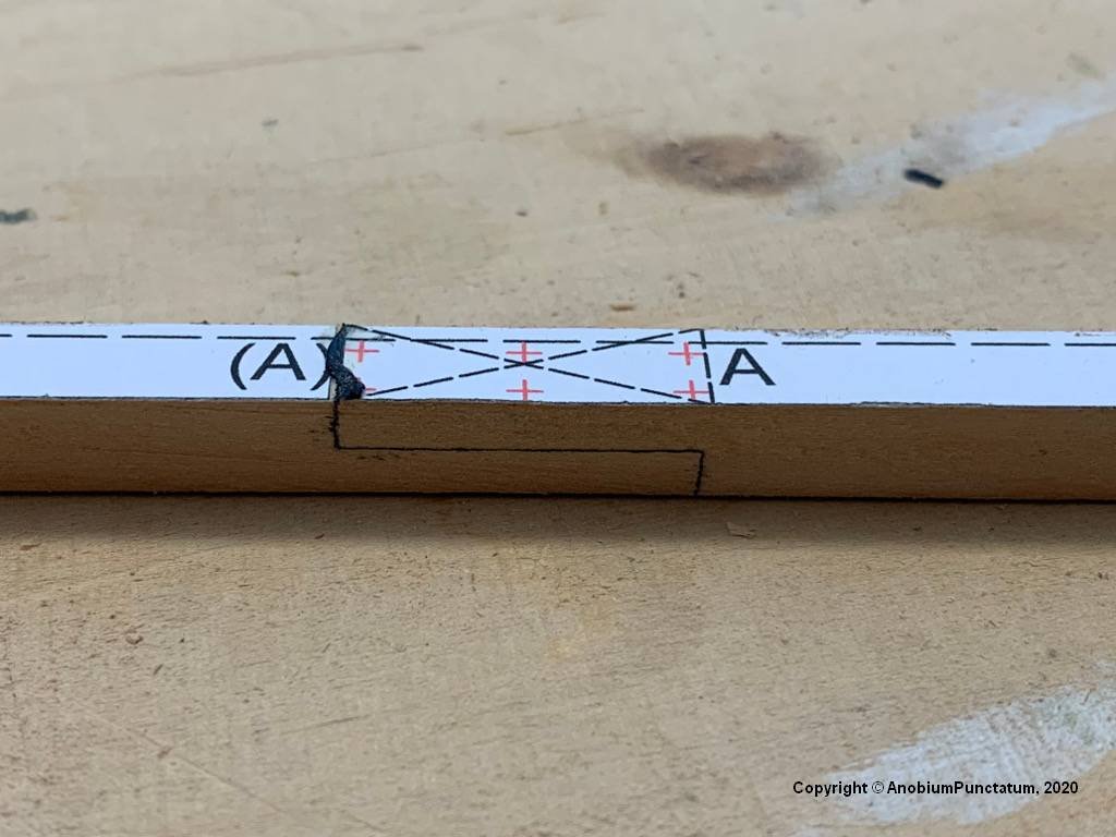
Now the Knee of the Head was sandes into shape. It tapers from the keel to the upper corner of the leading edge from about 10.5'' (according to SR 9.5'') to 7.5''; the trailing edge has a constant width of 10.5''. To transfer the measurements to the wood, I made small templates in CAD and glued them to the component. The stern changes its width from 10.5'' at the transition to the keel to 16'' at the top edge. I have also made a template for this. Because of all the sanding I forgot to take pictures of this stage of construction.
The last three pictures show the finished ensemble. On the second last picture you can hopefully see the wooden dowels I glued to the model instead of the brass rods.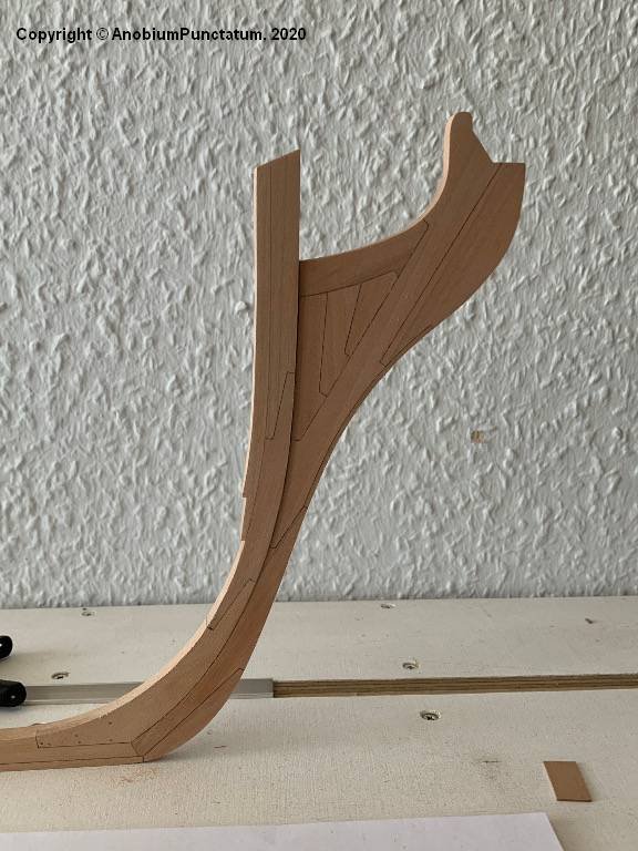
-
Thanks for the Likes.
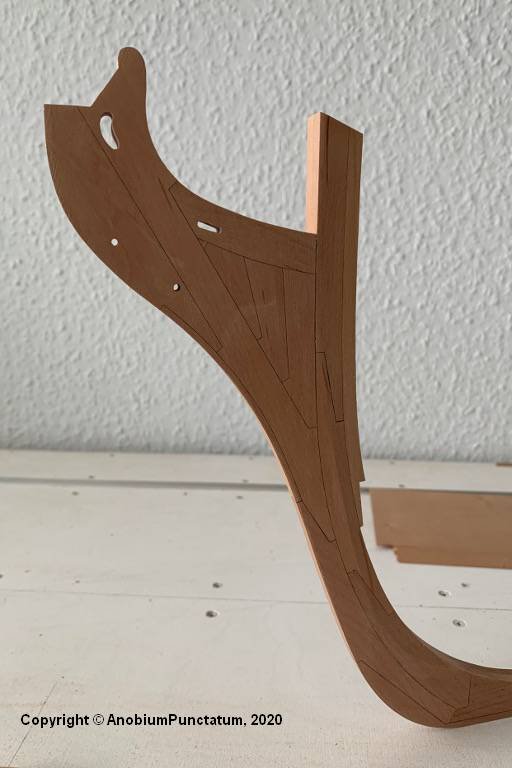
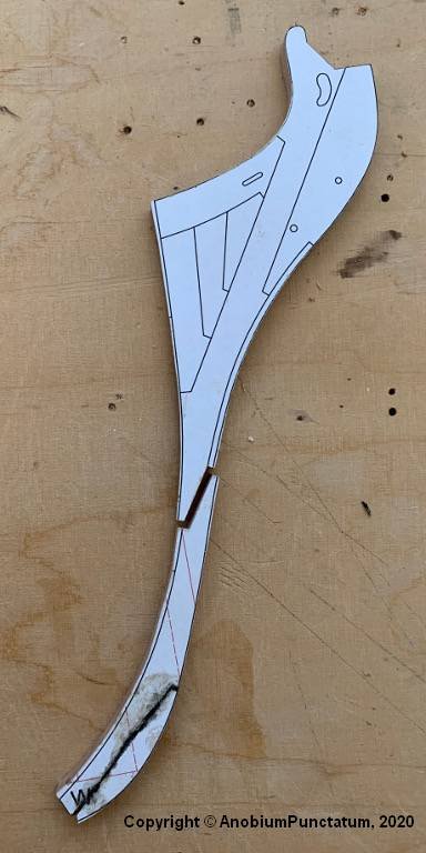
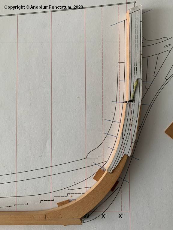
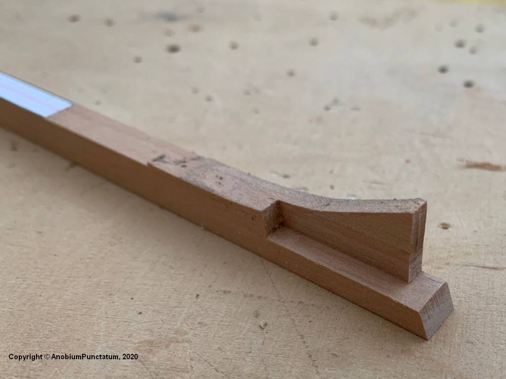
Today I prepared the "Knee of the Head". I have divided this one into two parts to make it easier for me to adapt to the stem later. First the chocks of the upper part were adjusted and glued together. For the caulking was again single layer cellulose used. To compensate for small tolerances, the templates were again exchanged for a single one after completion of the assembly. The main piece and the other components of the upper assembly were then added.
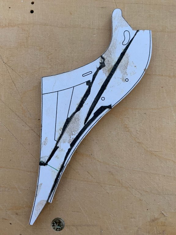
The lower assembly was then adapted and assembled.
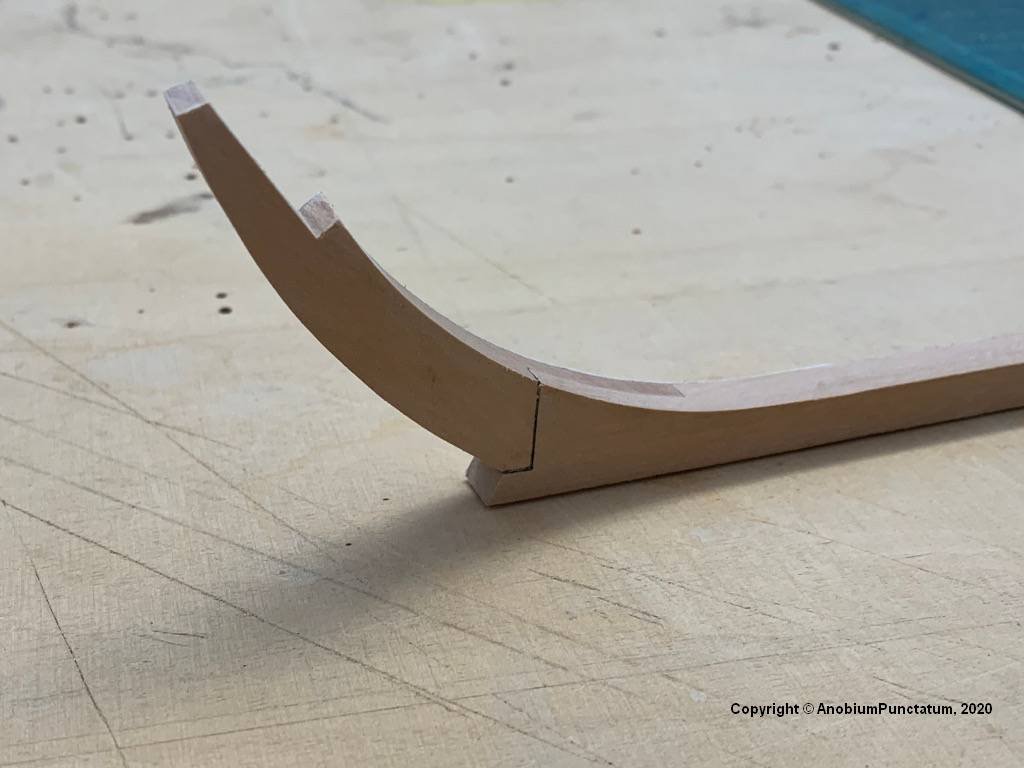
The following two pictures show the current status:
Since my vacation is coming to an end, the shipyard is now being exchanged for the home office. Nevertheless I hope to finish the "Knee of the Head" next weekend.
-
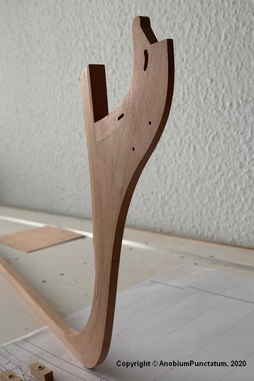
Further with the "Upper stem". There are only two parts that have to be glued to the lower part of the stem, which was already shown in the last part. The issue is complicated by the fact that even tiny angular deviations in the "Joint" lead to deviations at the upper end of the component. Aggravating is the fact that the component is about 1.7mm thicker than the keel
At first I built a small jig, which fixes the keel during the adjustment work. To check the position of the components, a template was aligned on the working surface and fixed with adhesive tape. Thin wooden plates were placed under the keel to compensate for half of the height difference.
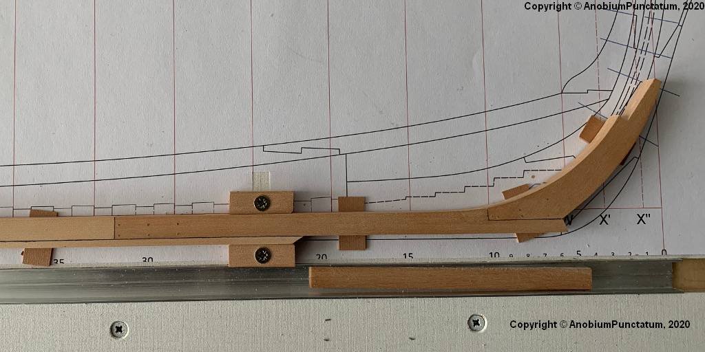
Next, the two components of the "upper stem" were glued together. A little more material was deliberately left at the sides to compensate for the construction tolerances later. Then the joint between the new component and the "Lower stem" was adjusted with my milling machine, chisels and sandpaper until the upper end of the stem was in line with the template. Now the components could be glued together.
The old templates were removed and a new template was glued and aligned. Finally, the stem was sanded into shape.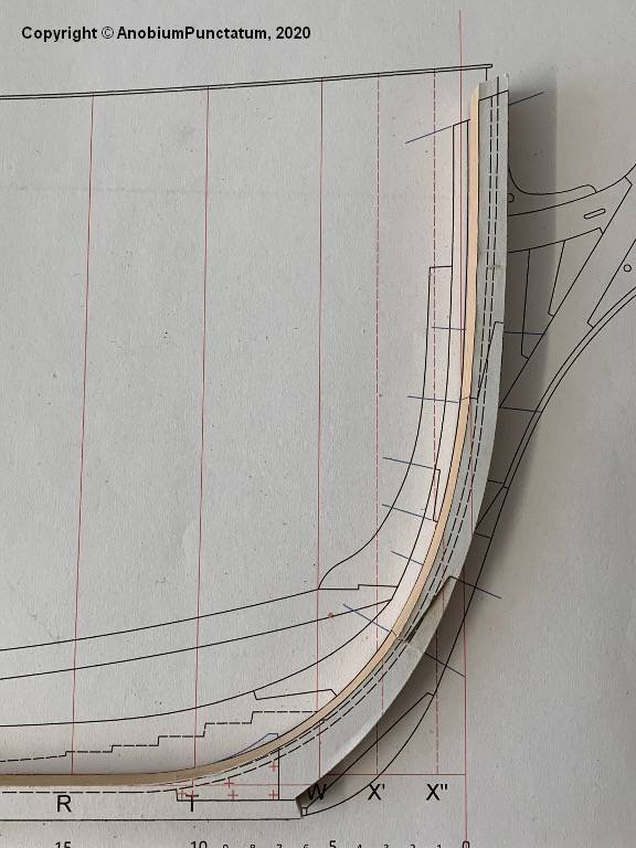
- mtaylor, Dubz, Edwardkenway and 9 others
-
12
-
Welcom to the Triton shipyards, Brian.
As far as I remember have all drawings the same scale: 1/48. So you have only to check, that you print every frame with 100%. For safety you can check the length of the ruler: 240'' = 127mm in 1/48.
- mtaylor and Jorge Diaz O
-
2
-
-
The description of my reconstruction you will find here.
On Easter Monday the time had finally come. The keel of his majesty's frigate HMS Triton was laid.
First the 5 components for the keel were sawn out.
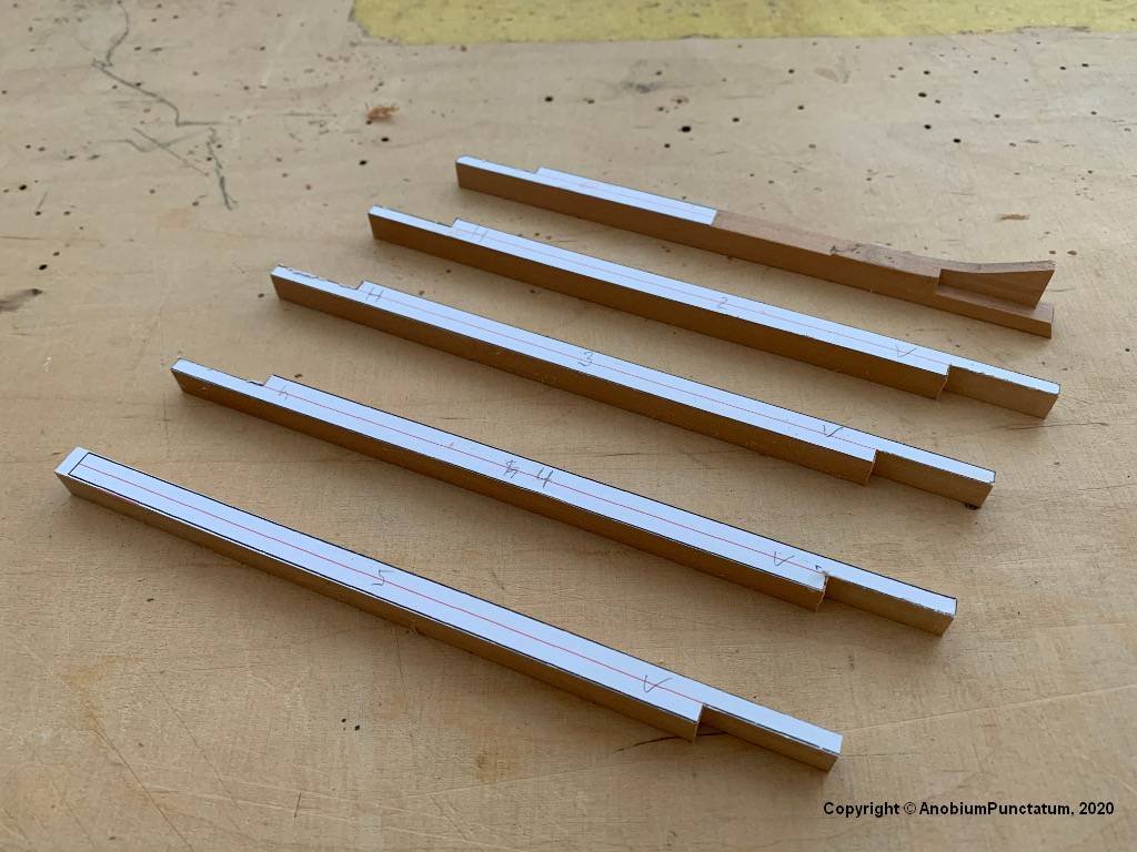
I have simplified the design of the joints considerably, as they will be completely covered later on by further components. I will continue to apply this principle during the further construction in order to adapt the building as far as possible to my craftsmanship.
The first cliff that had to be overcome is the joint between keel and lower stem. I worked this out with my milling machine and chisels.
After I had attached the wrong keel, the joints have to be dowelled. These dowels are a bit too big for the chosen scale, but I cannot draw pear wood thinner than 0.8 mm. I know that many modellers swear by bamboo, but I find pear on the finished model more discreet.
I have simulated the caulking with single-ply pulp.
-
Really nice progres Jorge. I like the coloring of your model.
- mtaylor and Jorge Diaz O
-
2
-
Chuck, I had the same idea. The Hanse Kogge is a really good model of the cog wihch was excavated in Bremen. I think it's the best model of this shiptype you will find in the market. I own a book from the museum in Bremerhaven which contains all drawings they made during the excavation. The model matchs this drawings quite well.
- popeye the sailor, Canute and mtaylor
-
3
-
Translation help needed - Renaissance German
in Nautical/Naval History
Posted
I speak German, but I couldn't read the text. I think that this are an old dialect and letters.