BANYAN
-
Posts
5,952 -
Joined
-
Last visited
Content Type
Profiles
Forums
Gallery
Events
Everything posted by BANYAN
-
 A great result using the plug method Eberhard; looks good and with the few minor repairs you mention will really good (especially at that scale). cheers Pat
 -
What a great concept Glen; your imagination, and more importantly your ability to convert your ideas into practical projects, is to be commended. I look forward to your adventures on this one also. cheers Pat
- 134 replies
-
- 5
-

-

-
- Captain Kidd
- bottle
- (and 3 more)
-
Great to see you back Steven and that you didn't let the mishap defeat you. cheers Pat
- 740 replies
-
- 4
-
-
- Tudor
- restoration
- (and 4 more)
-
Oliver Lang (senior) developed a new way of putting on chain plates. See "Extracts from ‘Improvements in Naval Architecture Improvements’ by Oliver Lang (1848) – British Museum 1397 e18"; specifically VI (page5) Preventer eye bolts for shrouds. Removed them from the strake in line with the chain bolts, which, as formerly fitted, destroyed the strake and timbers of the frame in that range, by cutting them to pieces, and wet coming into this part of the ship decayed the timbers; and, when under repair, I have seen the said timbers drop asunder, being cut off with holes and rotten. By removing those large eye bolts to the next strake above, it not only relieves the strain from that part, but preserves the strength of the timbers and prevents decay. This improved mode was adopted first in the Hind, 1805, afterwards in the Leonidas, 1807, Clarence, 1811, and has since become general. The eyes Michael asks about may simply have been (as suggested by MarkP), eyebolts for the preventer backstays prior to Lang shifting them to a separate strake as shown in the German illustration provided by Thanasis. cheers Pat
-
Congrats on your 'record' build Rob, might have been relatively quick but the quality did not suffer - a wonderful model. I have also very much enjoyed your journey and the various discussions. cheers Pat
- 3,560 replies
-
- 1
-
-
- clipper
- hull model
- (and 2 more)
-
Very nice work on your model Vlad, good to see you back. cheers Pat
-
Veeery niiiice! cheers Pat
-
Taking the time to fair the hull properly results in a much better model Bruce; we can all wait while you get this done. cheers Pat
- 43 replies
-
- 3
-
-
- mediator
- first build
- (and 1 more)
-
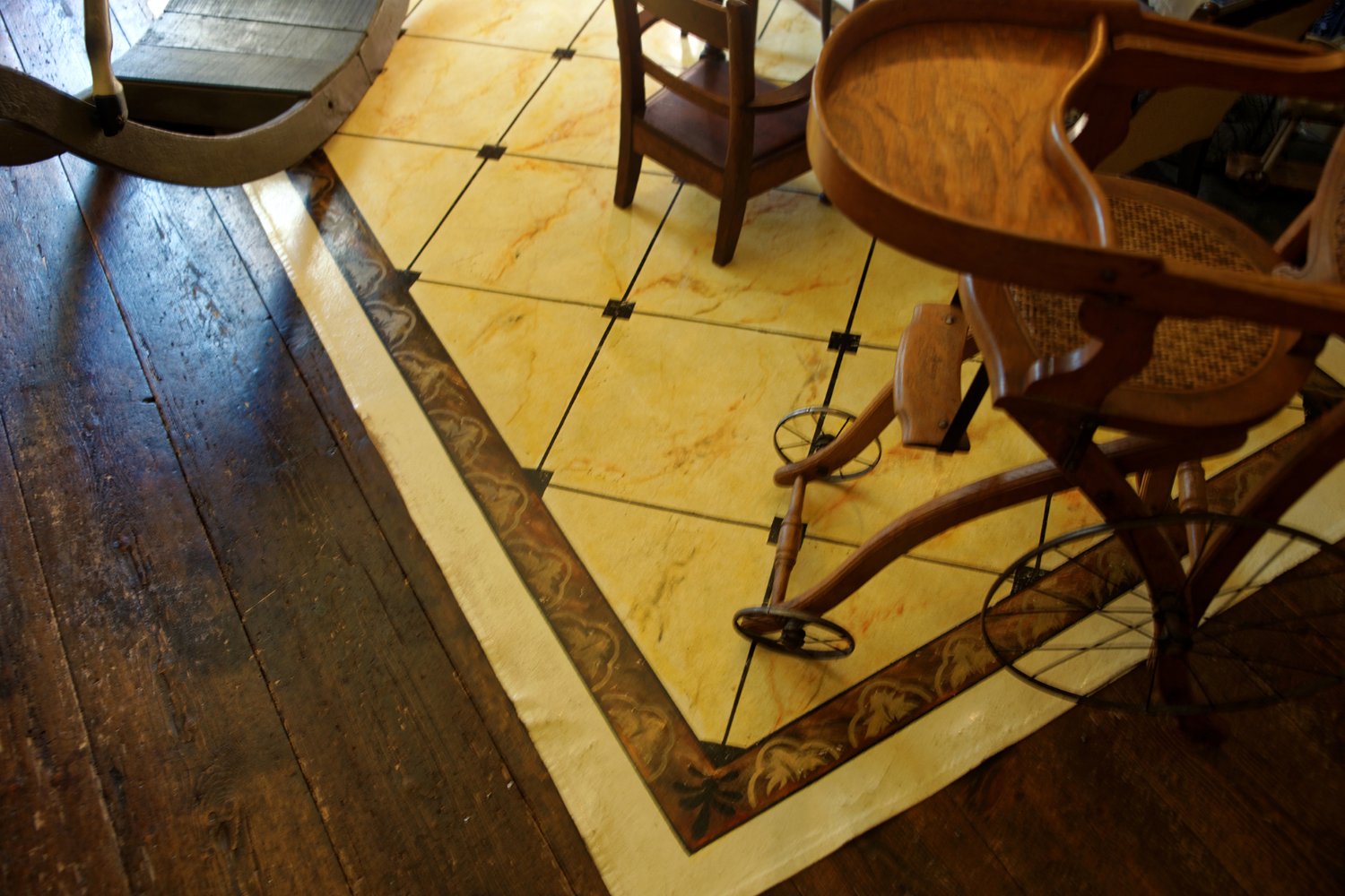
Here's an example of one of these oiled canvas mats. This was in a heritage house (Runnymeade) we visited in Hobart, Tasmania. I was pretty impressed with the overall quality. Youy can see the wear and tare Wefalck refers to on the edges where the mat is more prone t foot traffic etc. cheers Pat

-
Bob, thanks for posting that image - one learns every day. cheers Pat
-
Looking forward to seeing this little project progress Eberhard, especially the way you tackle them - I have some small boats to do soon also, so I hope you don't mind me poaching your techniques cheers Pat
-
Hi, I am not a yellow-wellie sailor (as in yachting) but from the imagery I have seen, the gaffs were in the lowered position and parallel with the boom; trysail gaffs (depends on what you are calling a trysail, as I have found there are many interpretation from small triangular storm sails to smaller replacement sails the same shape as the fore-and-aft sails) were only set-up when the sail was rigged (if the former interpretation). cheers Pat
-
Ultimation Model Slicer Anyone?
BANYAN replied to Bill Jackson's topic in Modeling tools and Workshop Equipment
Also an 'unnecessary' tool for me. These types of cutters use a 'V' profile cut (even when sharp) due to the razor blade cutting edge, leaving an oblique end profile that needs squaring for a good fit. I got rid of mine a long ago and simply hand or power saw cut 'fat' of the line, then touch up with my disc sander to the line. cheers Pat -
Rob, some clippers had two spiderbands (for belaying pins) at their base; perhaps an option? cheers Pat
-
The plaudits offered by other builders are well deserved Keith, let me add to the list of appreciative followers. This is a very high-quality model of an interesting subject - it has made for many hours of pleasant reading/viewing. cheers Pat
-
Rob, your model of GoS is looking great, and a pleasure to follow the updates. I have just noticed though, that you have used chain for the boat gripes; I am assuming this is as per research you have conducted. As the chain will have been pretty hard on the boat planking surfaces, and planks themselves, it may have been used in combination with wooden pad pieces to keep the chains off the planking, and/or leather (or other) Scotchmen (anti-chafing mats/pieces)? I admit not looking back through the log, so I apologise if I have raised something you have already discussed? For the purposes of modelling, however, what you present serves the purposes of how and what was used. Only raised as FYI. cheers Pat
-
NAIAD 1797 by Bitao - 1:60
BANYAN replied to Bitao's topic in - Build logs for subjects built 1751 - 1800
A great testimony to your skills Bitao; a truly high-quality model. cheers Pat -
Ditto, I have several of these to correct Rob; good to see you not taking the 'that'l do' path. cheers Pat
- 3,560 replies
-
- 2
-
-
- clipper
- hull model
- (and 2 more)
-
Stunning work and detail as usual Keith; it is always a pleasure to see the updates you have done. cheers Pat
-
NAIAD 1797 by Bitao - 1:60
BANYAN replied to Bitao's topic in - Build logs for subjects built 1751 - 1800
Love those deadeyes and offer congratulations on your resolving a better way of making them. I think Greg (dvm) says it all in his post. cheers Pat