yvesvidal
-
Posts
3,627 -
Joined
-
Last visited
Content Type
Profiles
Forums
Gallery
Events
Everything posted by yvesvidal
-

NONSUCH 30 - 1:24 SCALE - By Model Shipways
yvesvidal replied to kurtvd19's topic in REVIEWS: Model kits
Seems like a very nice kit. The finished model is gorgeous. Yves- 1 reply
-
- 2
-

-
Well, we know for sure that Vanguard Models releases their kit infinitely faster than Amati.... Time to start saving !! Yves
- 488 replies
-
- 7
-
-
- Indefatigable
- Vanguard Models
- (and 1 more)
-
Rob, The ladder are provided in the kit. Quite easy to assemble (you almost do not need glue). Then I stained them with some oak stain. The treenails are simply done with a mechanical (0.7 mm) pencil. They are sealed with multiple coats of Wipe on Poly. Yves
-
1/200 Trumpeter IJN YAMATO - issued by MRC/Gallery Models
yvesvidal replied to yvesvidal's topic in REVIEWS: Model kits
Mike, Yes that 1/10th scale model is located in the Japanese museum, commemorating the Yamato, if I am not mistaken. That model is incredible. Yves- 104 replies
-
- 3
-
-
- MRC/Gallery
- Yamato
- (and 1 more)
-
Rod, this model is absolutely superb. Like you, I love the wood contrast with the beautifully painted hull and the brass pieces. It makes for a very traditional model and a museum piece, at the same time. Thank you for realizing this unusual and often left aside model, of a beautiful tugboat. Yves
-
1/200 Trumpeter IJN YAMATO - issued by MRC/Gallery Models
yvesvidal replied to yvesvidal's topic in REVIEWS: Model kits
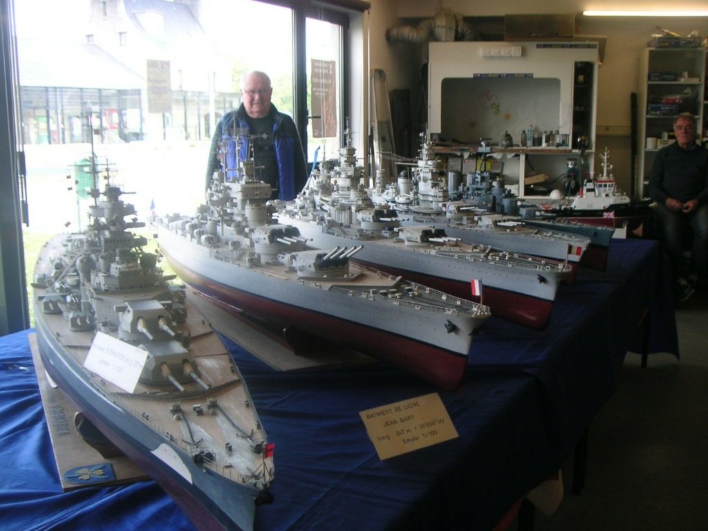
A few pictures from a French Forum, showing the YAMATO in 1/100 scale, basically 8 times bigger than the Trumpeter model: The gentleman who built the Yamato, also built a few other battleships, all in 1/100 scale: Yves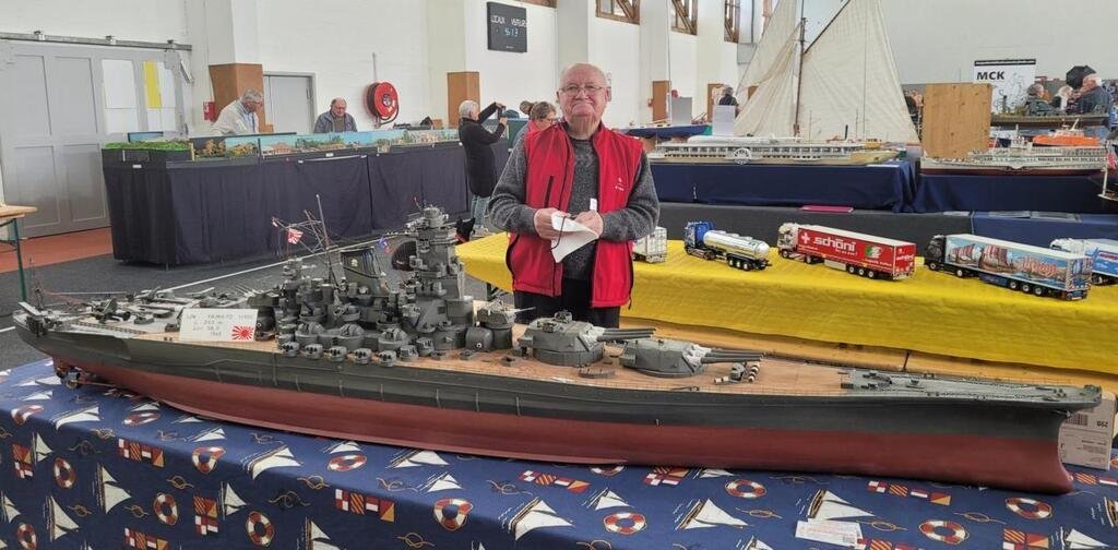
- 104 replies
-
- 10
-

-
-

-
- MRC/Gallery
- Yamato
- (and 1 more)
-
It looks like your friend will have his finished model, in a short time. Great beginnings so far... Yves
- 31 replies
-
- 2
-
-
- Shamrock V
- Amati
- (and 2 more)
-
Camel by RGL - FINISHED - Machinen Krieger - 1/20
yvesvidal replied to RGL's topic in Non-ship/categorised builds
I like that series of kit, especially their half hull submarine. They are great for dioramas or simply to display. I believe you can find figures of humans/girls that will fit inside certain machines. Yves -
Great idea to display the double capstan: it is always an interesting piece to start a technical conversation. Yves
- 857 replies
-
- 8
-
-
-
- Sphinx
- Vanguard Models
- (and 1 more)
-
Very interesting project of restoration for a dear person that steered you and motivated you into the path of scale model ships. I am so glad you can do that for her. Yves
- 44 replies
-
- 2
-
-
- Thermopylae
- Revell
- (and 3 more)
-
To get a sense of what the Harrier can do (Hollywood style), you need to watch (or re-watch) the movie True Lies with Arnold S. The end sequence is a blast to watch. Yves
-
What a beautiful sailboat. At times, I thought you had taken pictures of the real thing. Yves
-
Humpfrey, If you manage to paint and finish these crude Revell kits from the 70's, then a modern kit will be a piece of cake in comparison. Yves
-
I see that you have your modeling future, all planned. Yves
-
Beautiful work Tim. I like your approach to models, there is something different and special coming out of them. The weathering is very subtle and the overall effect is sublime, in my humble opinion. Yves
-
I ponder the same question.... If I had the money and knew some motivated people, I would open a small museum called the 1/48th Scale museum or the "1/4" to the Foot" Museum. I wish I could display the large collection of brass and plastic trains I have, planes and ships and invite other modelers to join in. I see a need to educate young people and give them the knowledge and interest to build things with their hands. Where I live (Raleigh, NC), there is absolutely nothing of that nature and this city (town would be more appropriate) is a cultural abyss when it comes to this kind of things. I still have to find a club where enthusiasts meet and discuss their passion. I am not even envisioning a public display.... Anyway, it remains a dream. Yves
- 460 replies
-
- 4
-
-
- Finished
- Flower-class
- (and 1 more)
-
Fantastic model, Alan. I am glad you followed my crazy recipes and insanity for large models 😁 I really like your case as it gives the model a very professional/museum like appearance. Yves
- 460 replies
-
- 2
-
-
- Finished
- Flower-class
- (and 1 more)
-
Richard, We all hope you are doing good and finding some time to work on that beautiful model. Yves
- 454 replies
-
- 1
-
-
- Union Steamship Company
- Stepcraft 840
- (and 3 more)
-
Microscale Kristal Clear is the product I was looking for. Very easy to use and makes great and realistic portholes: Yves

-
Kevin, there is a product by MicroScale that does a fantastic job of turning portholes into clear glass. I used it for my 3D printed Corvette, with much bigger portholes than your Britannic. The name escapes me but you will be able to find it easily. Dries very fast and very clear. Yves
-
SD 14 by RN77 - Marcle Models - CARD
yvesvidal replied to RN77's topic in - Build logs for subjects built 1901 - Present Day
As described by Kevin, this endeavor is complex and enormous. Good luck. Yves -
De-construction and re-construction: Sometimes, we need an additional challenge !! 🙂 Yves
-
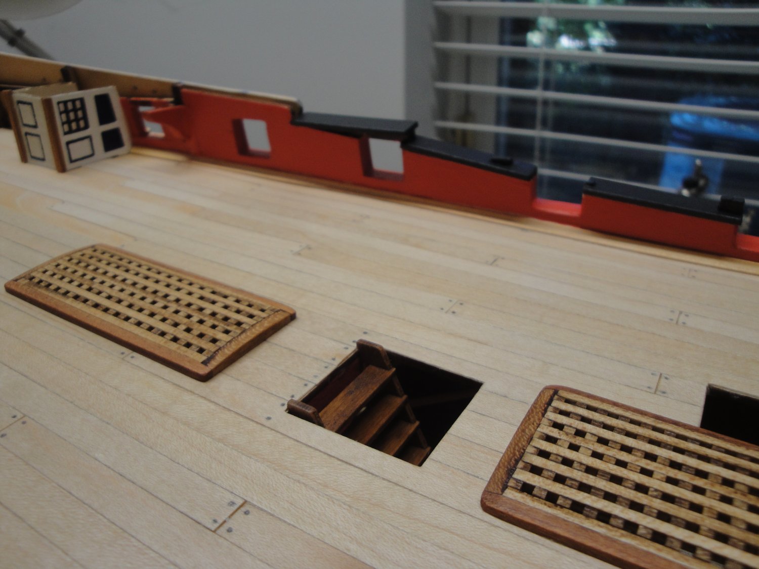
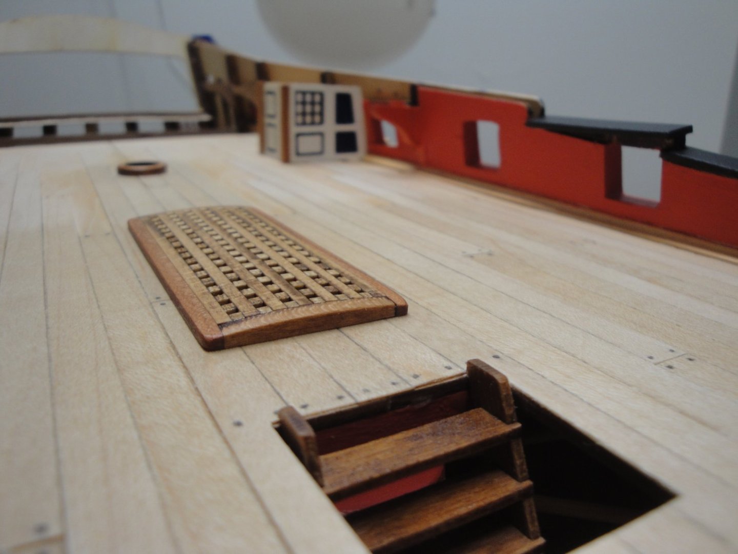
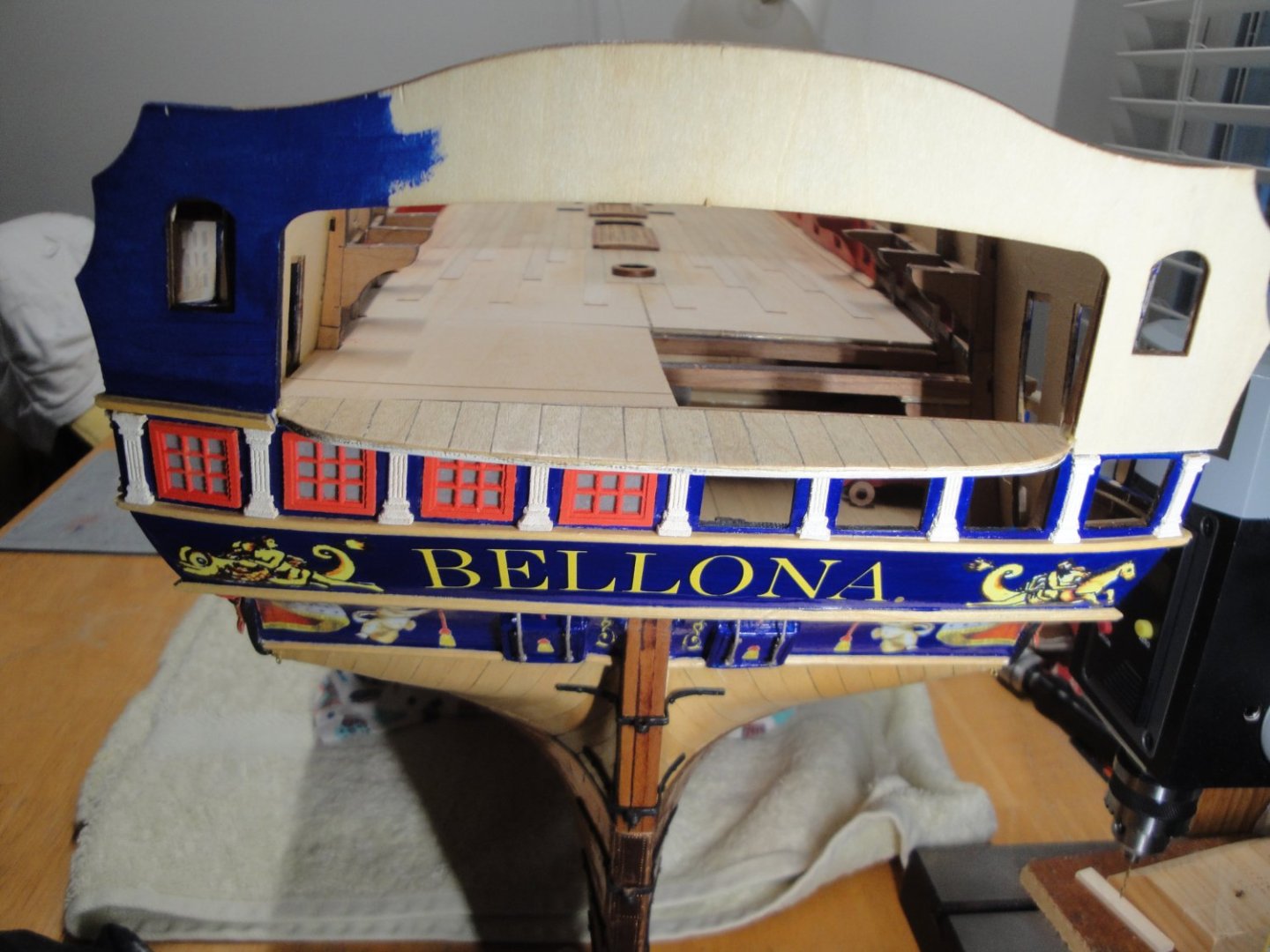
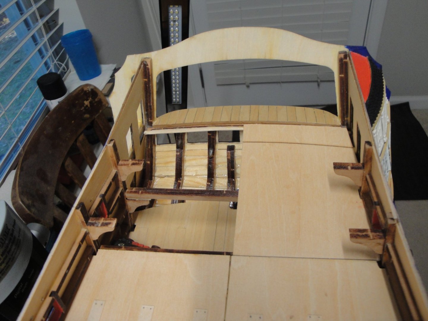
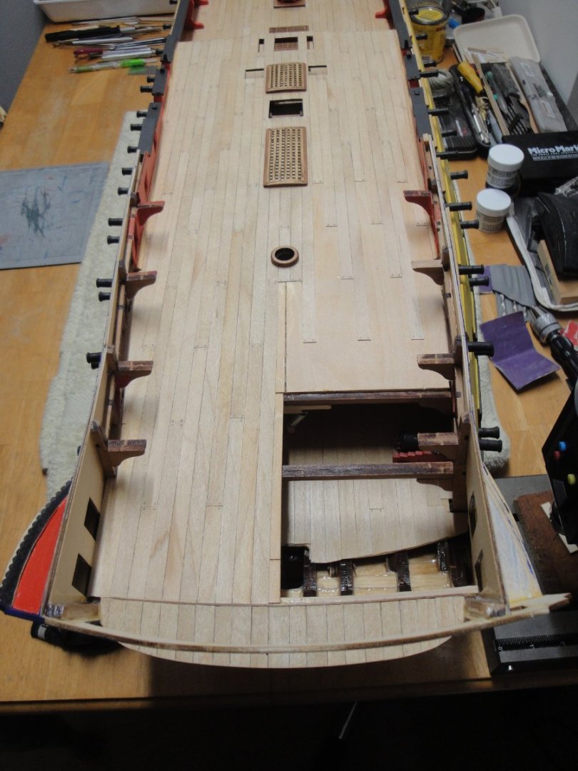
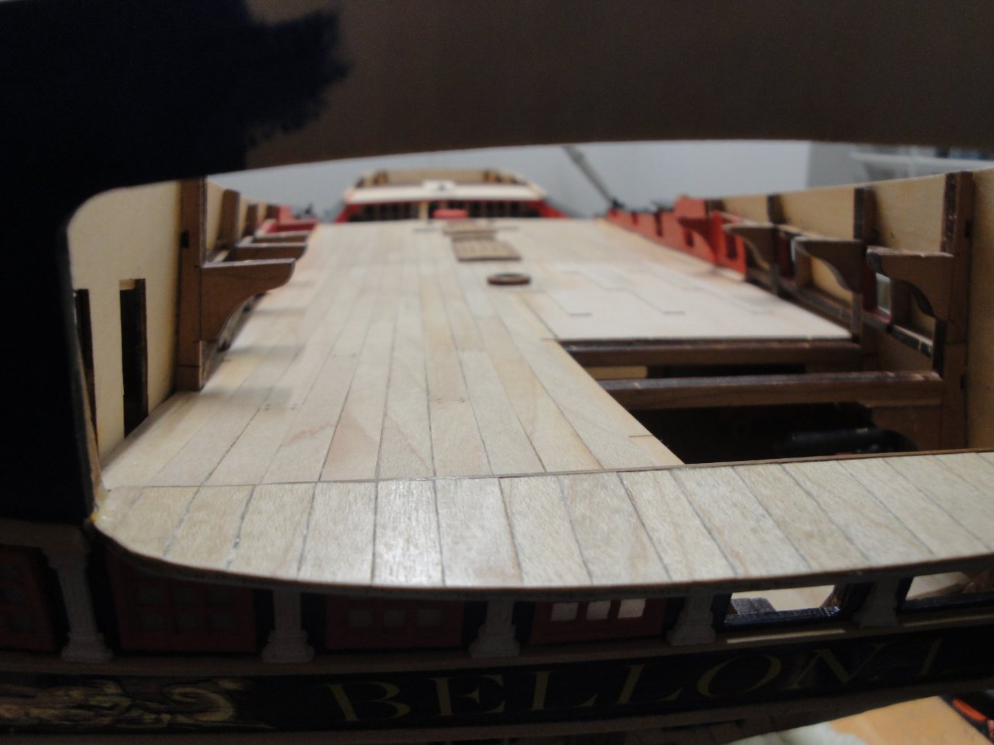
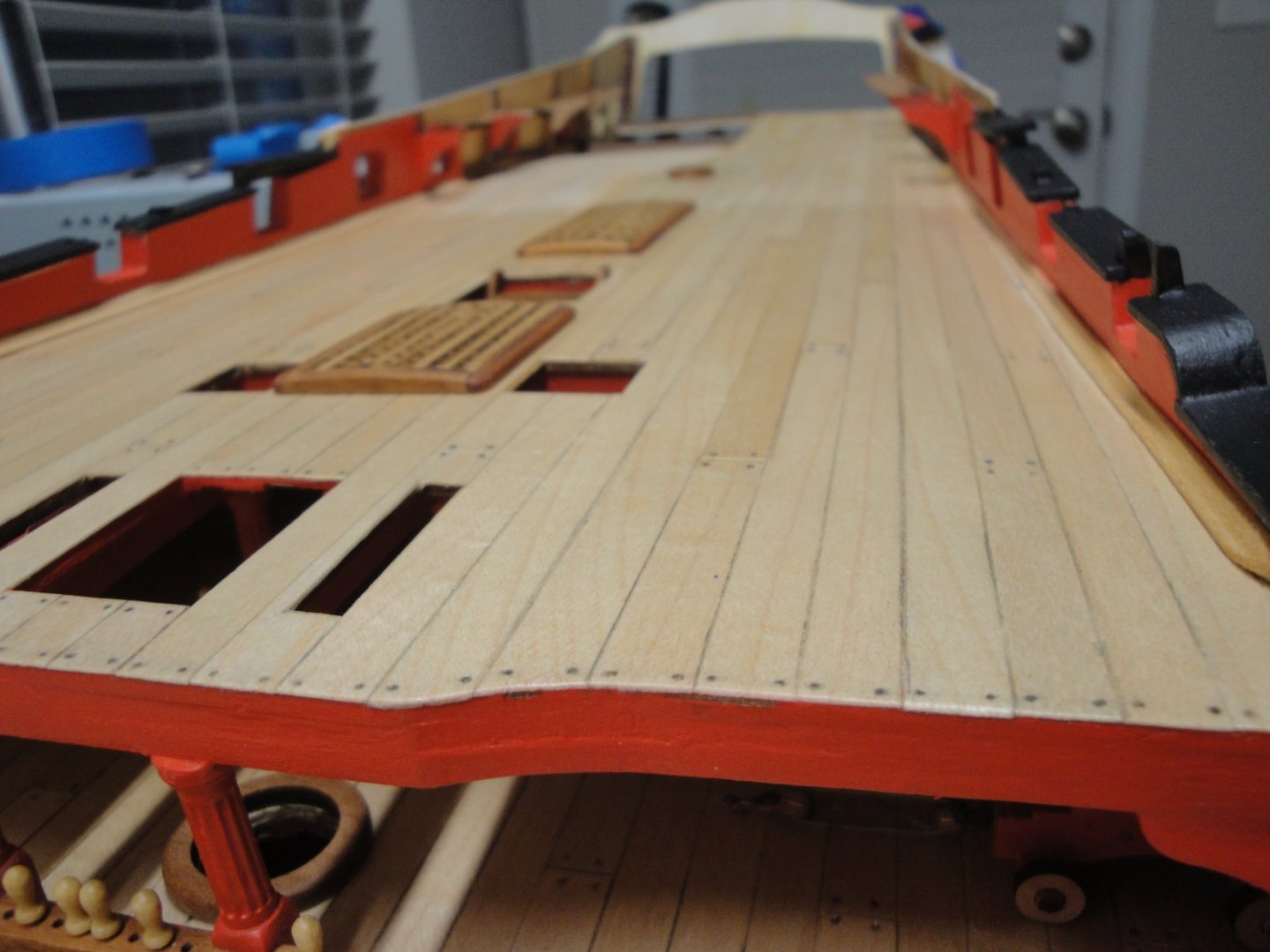
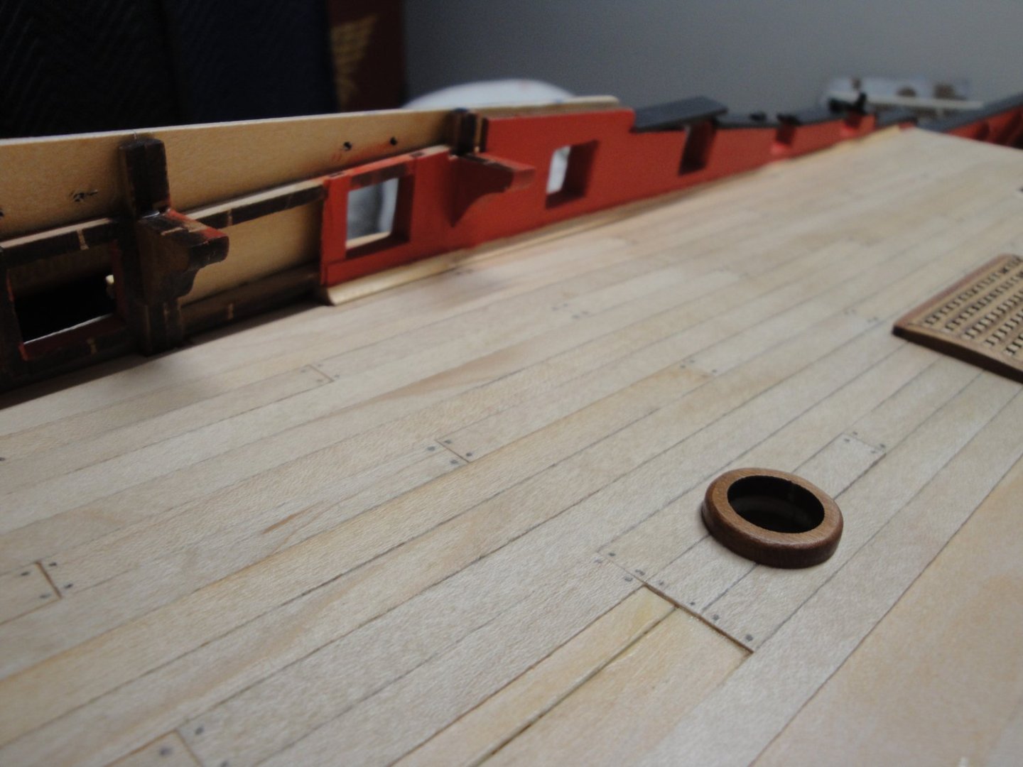
Just a quick update on the Quarterdeck: The gratings are made with a special box that came with Session #4. Apparently, it is an "upgrade" kit, that contains all the hatched and grtings for the Bellona. These gratings are pre-cut, slightly convex and are ten times easier to assemble than the original hatches provided with Session #2. I did not know that, because there was no relationship between the instructions that came with my kit and that "upgrade" kit. Anyway, I will be using these gratings from now on and may even try to remove the visible ones, on the main deck and replace them with these. We will see..... The fundamental problem with this Bellona kit is ..... THE INSTRUCTIONS or more precisely, the LACK of them. I find myself spending a lot of time, figuring out what is going to be my next step and how I am going to do it. Honestly, I don't think you can finish the ship by following blindly the instructions and their sequence of order. Anyway, enough rambling..... I am now working on trying to complete the rear quarterdeck. Before you can finish the planking, you have to install the poop windows: You absolutely need a finger on each side to position correctly these window frames. THEN, you can glue the sub-frame for the planking: And then you can plank..... As usual, a couple of Wipe on Poly on the maple planks, to give it more depth and protect the wood (0.5 mm thick). Above: that is a very big quarterdeck..... You could play bowling on it Oh, I forgot to mention: the lack of bulwarks in visible places such as this one (see below). The kit has nothing, so it is up to you to fabricate it: Yes, all this will be easily visible, as it surrounds the main wheel. At this stage, I have done everything I could in the quarterdeck.... I have been trying to postpone the inevitable task of building the second gallery and the "pleasure" of cutting carefully 81 window panes.... Call me procrastinator if you want, but there is absolutely nothing fun in this process. I am going to try to gather my courage and energy and do it again.... It is that story of needing one finger on each side..... to position perfectly these windows frames. If you follow the official instructions, you just cannot do it...... Every access you can get to the inner galleries is so precious. Yves

- 507 replies
-
- 16
-
-
Incredible model and lots of very thorough explanations and details. This model belongs in a Museum !!! I am using your Build Log on a regular basis as a reference for my Bellona. Yves
- 857 replies
-
- 4
-
-
-
- Sphinx
- Vanguard Models
- (and 1 more)
-
Mike, this is superb !!! It is now time to start the CAF Bellona..... Yves
- 150 replies
-
- 1
-
-
- agamemnon
- caldercraft
- (and 1 more)