


SJSoane
-
Posts
1,641 -
Joined
-
Last visited
Content Type
Profiles
Forums
Gallery
Events
Posts posted by SJSoane
-
-
-
Thanks, Håkan, we moved to a rural area in Montana with limited resources like shops, but beautiful views.
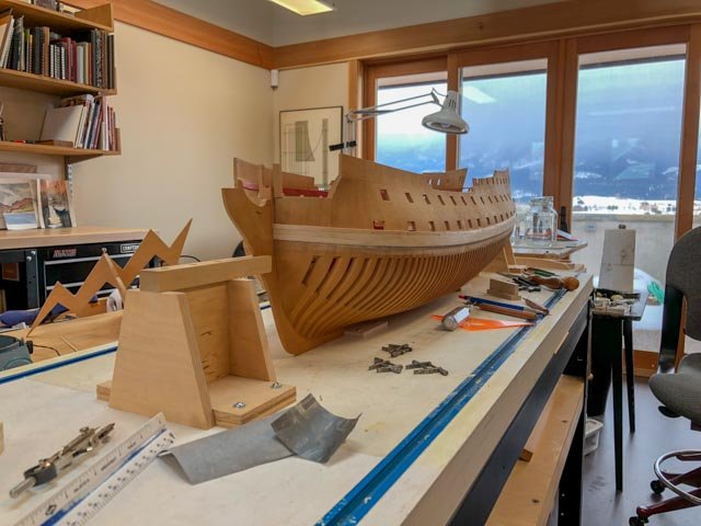
druxey, my wife is not only a retired architect, but also furniture designer (two of her designs are in the Kirkland Museum of decorative arts in Denver). The lightning bolt is a prototype for a candlestick holder she is working on. We share the shop, split right down the middle. We share most tools, but not my carefully honed chisels....🙂
Mark
- dvm27, paulsutcliffe, daHeld73 and 2 others
-
 5
5
-
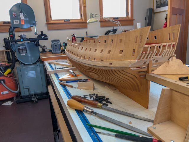
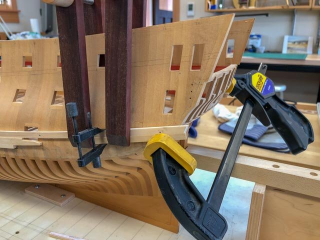
Finished the last port plank in the upper two strakes. Now I need to trim up the lower edge before beginning the final two strakes.
I got this done just in time, because you can see in the third photo a lightning bolt is about to attack the ship from my wife's side of the shop...
Mark
- DORIS, robdurant, garyshipwright and 20 others
-
23
-
Thanks, Siggi, that makes sense.
Mark
-
Siggi,
It is looking great. You are inspiring me to try to move faster!
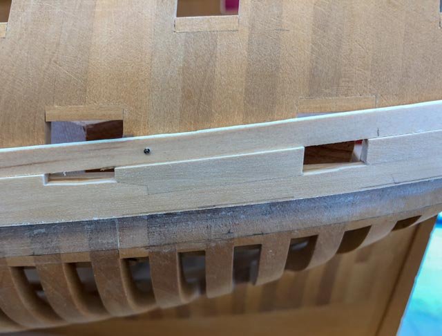
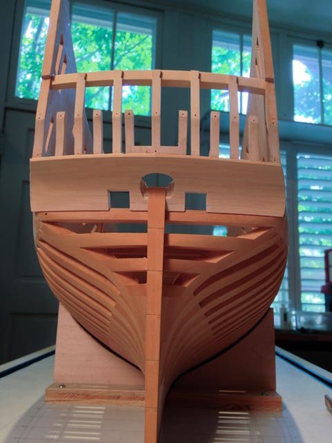
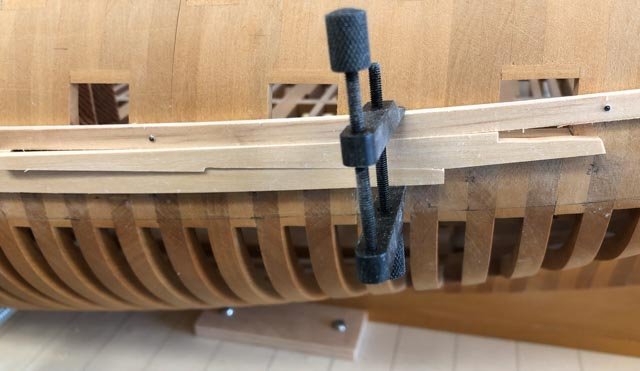
I notice the line you have drawn for the sheer rail, the next line of thicker planking further up the side. It does not match up or align with the "knuckle" or sharp bend in the foremost frame. It may be different in your ship, but in mine the two line up (see photo below).
Best wishes,
Mark
- mtaylor, giampieroricci, popash42 and 8 others
-
11
-
Thanks, druxey and Ed, you have both caught me from mistakes in the past, and please keep checking up on me!
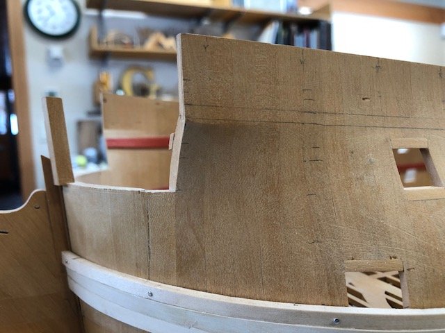
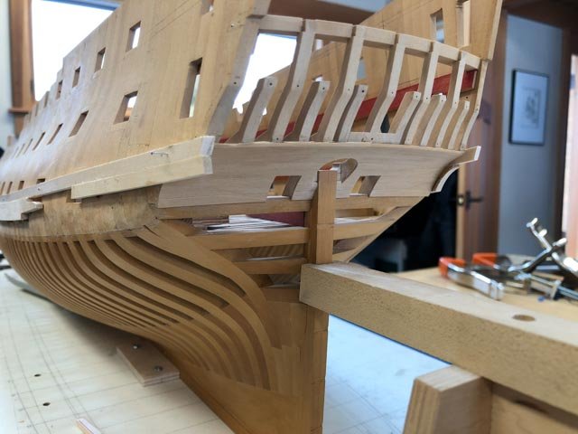
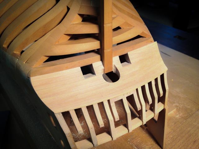
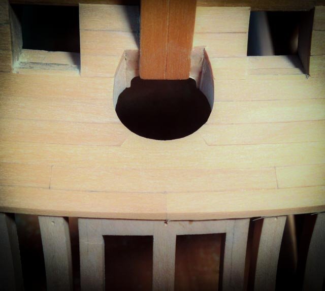
In this case, I followed the advice in the Naiad book and in David Antscherl's Fully Framed Model books, and planked the counter some time ago. Although it hasn't shown in my recent photos, I see. Here are photos from a few years ago when I planked the counter.
The photo from the port showing the wales underway does raise an interesting question on this, though. I had started to shape the wale to the counter on the starboard side, as you can see, but I quickly realized that I was likely to damage the counter because I could not see very well upside down. I assume I will have to turn the hull upside down again, and then shape the wales to the counter. And as long as I am at it, I wonder if it would be a good idea to color the wales upside down, where I can really see the critical painting edges between the lower edge of the wale and the hull (which remains unplanked in this model style), and between the wales and the counter.
I also need to try a few samples of coloring, which at this point will include Fiebing Leather Dye, Speedball ink, or possibly airbrushing with diluted acrylic paint. I am looking for something revealing the wood grain slightly, but I don't want to mess with a top coat of tung oil which I see has caused some problems for others in the past. As Ed well advises, I will test extensively off the model first!
Best wishes,
Mark
- Siggi52, Captain Poison, druxey and 14 others
-
17
-
Hi Gaetan,
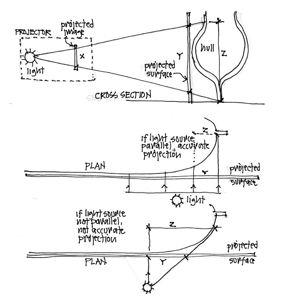
I have been thinking about your projector experiment. I have attached a diagram showing what the issues might be.
In the first diagram, showing the project and ship hull from the side, if the light source is a single point, then the image lines will radiate away from the source. An image at X is projected to a greater Y on the projected surface, but the image will be an even greater Z at the hull.
The second diagram shows the setup in plan. If the light source creates parallel rays, the image on the projected surface will be accurate, even around the curve at the bow. But if the light source is a single point, as in the third diagram, the distance on the hull at Z will be greater than the distance at Y on the projected surface. and the curve at the bow will not be accurate.
You could avoid this problem if you could take each point on the projected surface, and then project it onto the hull exactly at right angles to the projected surface. Maybe this could be done with your laser beam.
Just some thoughts in your very interesting experiment!
Mark

-
Two pieces to go. I discovered, when recutting the upper, sternmost plank of the wale, that leaving it much longer than necessary helped with steaming to the correct shape. Having a little extra length reduced the springback and gave a better purchase when gluing. Sometimes, as in the case of my first failed blank here, cutting rough blanks too close to final size is "penny wise and pound foolish". New lessons learned all the time.
Mark
- paulsutcliffe, robdurant, mtaylor and 11 others
-
14
-
-
-
-
-
Hi Doris,
Nice to see you back, and with this exceptional project.
Mark
- FrankWouts, mtaylor, DORIS and 2 others
-
5
-
-
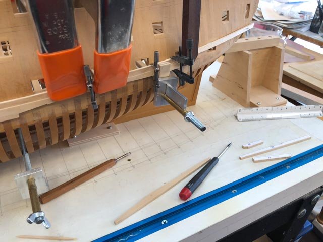
calling all clamps, calling all clamps, report to the port side...
After going off in a huff and recovering my composure, I got going again. Just four more planks to install on the port side, upper two strakes (blanks are next to the screwdriver in the photo below). This is a big step, because it locks in the two sides longitudinally at about the same level of humidity.
Good days for working in the shop here in Montana. We hit minus 11 degrees fahrenheit last night, the town of Butte about 180 miles away hit minus 24 degrees, the lowest in the lower 48 states, and the wind chill factor on the eastern plains hit minus 36 degrees. Not much point in going outside.
I can only begin to appreciate how cold it got on a winter North Atlantic station, or rounding the horn, taking in sail.
Best wishes,
Mark
-
Alan,
Once I walk away from mistakes and eventually regain my composure, I think of my restarts as just practice. It sounds like you got some exceptionally good advice. My own gunports benefitted greatly from striking a line along the length of the hull, so I could see how each flowed to the next. Without seeing the overall line, it would have been too easy to slightly misalign and you would never know until it was all done and too late.
Having said this, I haven't quite regained my composure on my own recent Bellona mistake; I will follow your lead in this!
Mark
-
I always knew we are especially wonderful, our scrap boxes confirm it!
Mark
- mtaylor, druxey, paulsutcliffe and 1 other
-
4
-
Håkan,
That first photo shows just how complex the bevel must be to roll from clinker to carvel at the rabbet. Well done.
Mark
- mtaylor, popeye the sailor, G.L. and 1 other
-
4
-
-
I cut and cut, and it was still too short...
There went a morning's work, with a piece pre-trimmed too short to meet the gunport edges. I tried the board stretcher, but it just could not quite manage the task.🙂
All of the pieces from this point to the stern are just a smidgeon too short, so I have to remake them all. My CAD drawing slightly underestimated the length of the wale when it was turned into a true projection, and so I cut the blanks at the stern with too little to spare. I had cut them long enough oversize on the starboard side to adjust when put to their true location, but for some reason I failed to do so on the port side. Just when you think you have got a process down, the demons jump up and grab you.
Time to go do something else!
Mark
-
-
-
-
Thanks, Mark. One learns a lot about full size construction from little models. I still marvel at the idea of the shipwrights steam bending a 32 foot long, 8 inch thick by 12 inch wide plank, hoisting it into position several stories off the ground, and then clamping it before it begins to cool. Just about impossible for me to comprehend.
Yes, we are living through what old-timers here call one of the worst winters in memory, true across much of North America and Europe, I understand. (It still doesn't feel as cold as when I lived in London many years ago in a student room with a single bar electrical heater. I gained a strong appreciation of British toughness in the face of weather, certainly tougher than I was...🙂)
But between the dumps of snow and low wind chill factors, we occasionally get out to ski here. And of course, a big snow storm is a terrific opportunity to brew a big pot of coffee and work in the shop!
Best wishes,
Mark

HMS Montague 1779 by garyshipwright - 74-gun Alfred-class
in - Build logs for subjects built 1751 - 1800
Posted
Gary,
The planking is looking really great. Are you going to leave some of the side un-planked to show the framing?
Mark