


SJSoane
-
Posts
1,621 -
Joined
-
Last visited
Content Type
Profiles
Forums
Gallery
Events
Posts posted by SJSoane
-
-
druxey, I have pondered putting little dabs of wood planking under each truck, but it seemed it would be confusing. Acrylic is an interesting idea. Do you know of any examples where someone has tried this? Would it be a little rectangle under the entire carriage, or separate pieces under each truck? I imagine I could drill down through the trucks into the acrylic for pins. The deck is 4" at 3/16" scale, so only a 1/16" actual.
Hi Alex, thanks for the welcome back. It has been a long time! I was just looking at your Sphynx build, admiring your gun barrels. My efforts at casting metal guns have not been satisfactory, and I was thinking about turning them like you did. Can you show me the shape of the cutting bit you used with your duplicator, to allow cutting close up to each side of a ring, but still having a smooth surface in the rest of the barrel?
Mark
-
I wonder if the Nautical Research Guild would do a line of neckties for modeling...👔 Pretty sure I would not wear one, but you never know.
I am three strakes away from the end. The last ones will require some bending and shaping, so will slow down my progress a little.
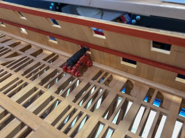
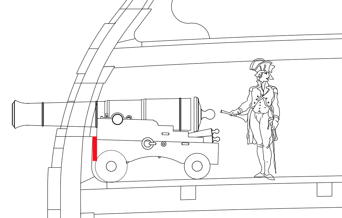
While waiting for glue to dry, I started thinking ahead to some next steps. At some point, I need to install the guns on the gundeck. I have not figured out a way to pin them in place, since I will not have decking under them. Perhaps a spacer connecting to the spirketting, as shown in the red rectangle in the drawing below?
Mark

-
Thanks, Michael, very clever!
-
Hi Gaetan, I have wondered about building at your 1:24 scale, since I highly admire your work. But I would have no room in the house for the final project!
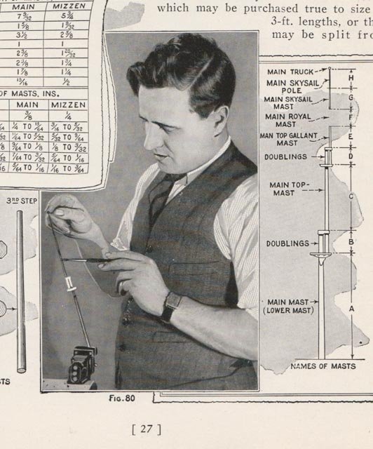
I was just given a booklet, entitled "Building a Model of the Flying Cloud, by James Tate, 1929. It has a lot of interesting information, and also images of how modelers apparently used to dress, with tie and waistcoat. At least the waistcoat keeps the tie from wrapping around your lathe!
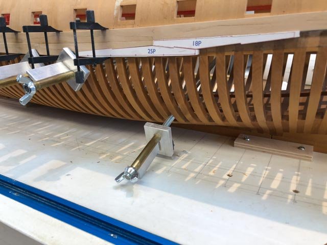
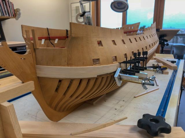
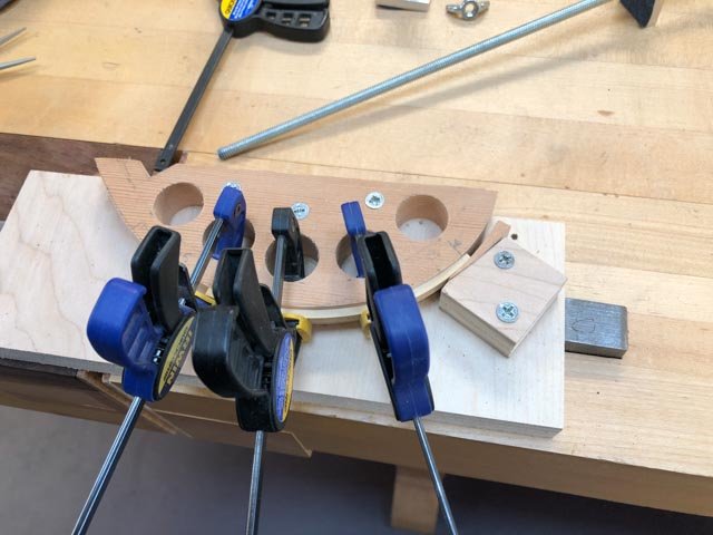
I am proceeding with finishing the wales. Pretty straightforward after lots of practice so far on this little project. Here are a few unusual items of note:
In the third photo, I am showing a strake that still had too much springback after clamping to the hull overnight, I avoided forcing the piece into place by faying a small spacer onto the inner face to match the curve of the hull, and after it was attached, I faired the outer face to match the rest.
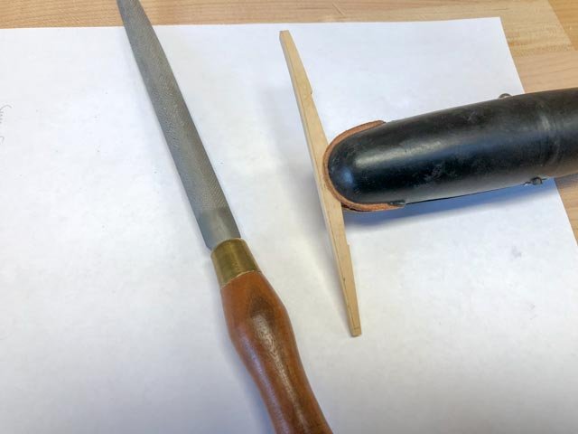
The first photo shows a jeweler's clamp I bought many, many years ago, and never used. But I have acquired a case of tendonitis, which makes it painful to hold small pieces for sanding. This clamp eases the pain. Should have used this years ago.
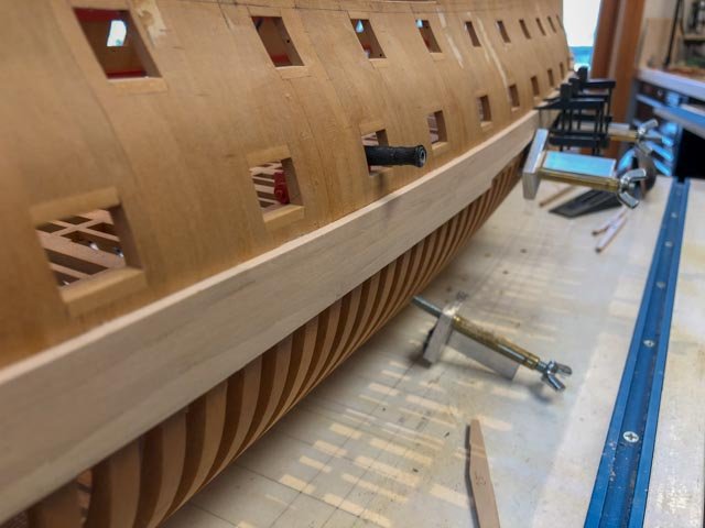
The final photos show progress, including a closeup of the hooked joints.
Mark
-
Hi Michael,
I am just catching up on your log after some time away. I am very impressed by your willingness to rework things until they meet your very high standards. A lesson for us all.
A quick question regarding the rail on the boom. Were you using the sanding block on a rail previously roughed out on the mill, or was that a new rail shaped entirely with a sanding block? If so, how did you index the slots?
Great work!
Mark
-
Hi Ed,
Just catching up after being away for some time. The detail and craftsmanship continues to amaze. One does not realize just how many specialized parts and pieces there are, until seeing your closeups. All the more astonishing how all of this evolved over time, and became more complex, in the latter years of the sailing ships. Fewer crew, more complexity in the machine.
Mark
-
-
Beautiful work, Doris. I apologize if I missed it earlier in your post, but are you making negative moulds into which you press the clay? If so, are you carving those from wood?
Mark
- Piet, FrankWouts, DORIS and 2 others
-
 5
5
-
Just catching up. It looks lovely, Gaetan. Exquisite craftsmanship, as usual.
Mark
-
Greg, Grant and druxey, thanks for the comments about clamping. I don't know why I could not come up with such a simple idea the first time around. It seemed obvious after getting away from the problem for six months.
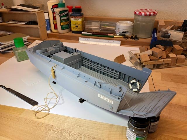
Mark, I did not think to photograph the LCVP build, probably should have. It was a nice break to have the parts already made, just needing assembly and painting.
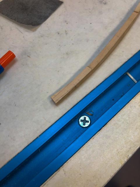
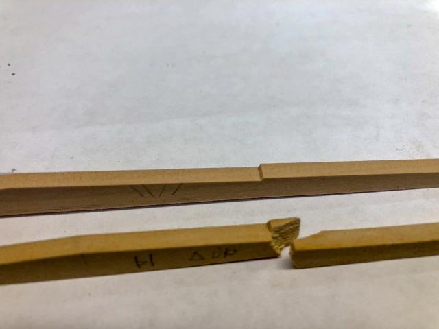
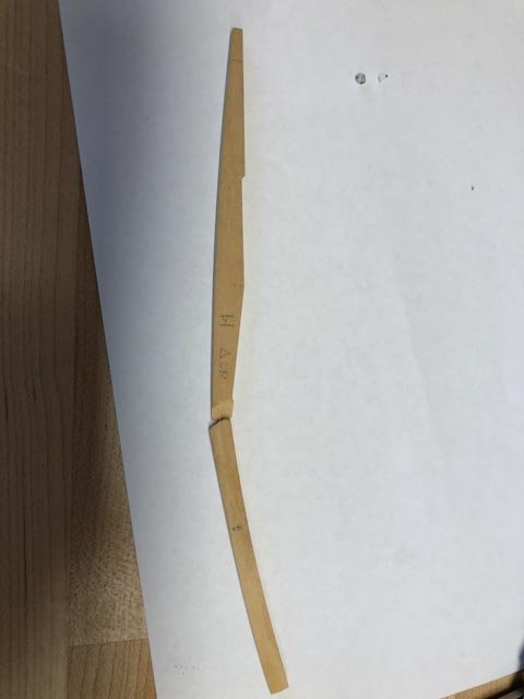
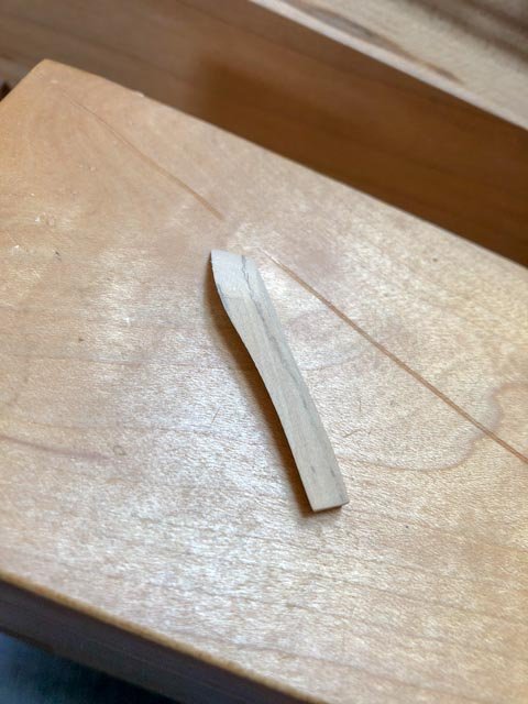
Hubac's Historian, I looked at the split more closely after your comment, and as you can see below, it did not split along the grain which is running mostly parallel to the piece. It split on a diagonal across the grain, which perhaps makes sense because I understand a failure in bending wood will always result from the fibers in tension on the outside of the curve letting go. Some steaming techniques at full scale have a compression strap on the outside to prevent this.
Also, I notice that it broke at the point of the hooked scarph shoulder (see unbroken one beside it). I vaguely remember an architectural structures class that said failures will tend to occur at the points of discontinuity in the material, and this seems to confirm it. I may have this wrong, if any engineers want to correct me.
I also noticed that this particular piece is the longest in the wales, at 37' by 6" by 1'-9" at its widest. Can you imagine how they hoisted the real thing out of a steaming box and clamped it onto the hull before the plasticity disappeared? Working at scale continues to make me appreciate the complexity and craftsmanship of the real things.
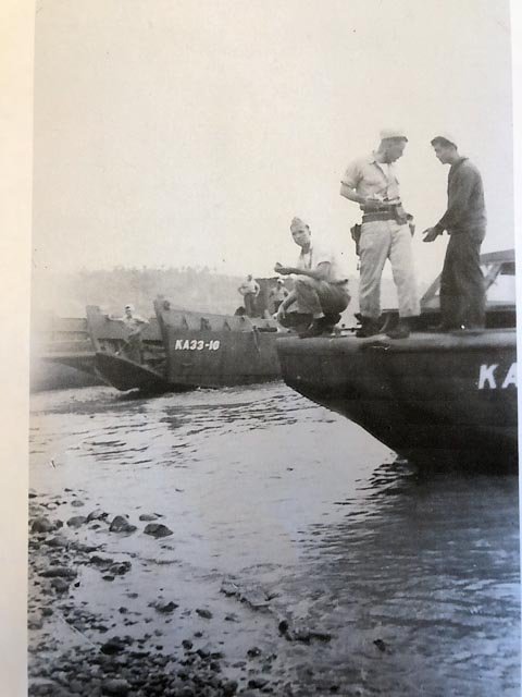
Druxey and Alan, thanks for the comments about my father. He was only 21 at the time, and three quarters of a century later he could still recall vivid details of his service in the LCVPs, some prompted by looking at the model!
Mark
-
Hi everyone,
It has been a long time since the last post. We had 11 groups of friends and family come to visit us in our retirement this spring and summer, and however nice it was to see them all, it sure killed any momentum I had going on the Bellona. No work at all this summer.
I also took some time away from the Bellona to build a plastic model of an LCVP (Landing Craft Vehicle Personnel) for my father's 95th birthday. He is seen with the sidearm in the first photo, with an LCVP in the background.
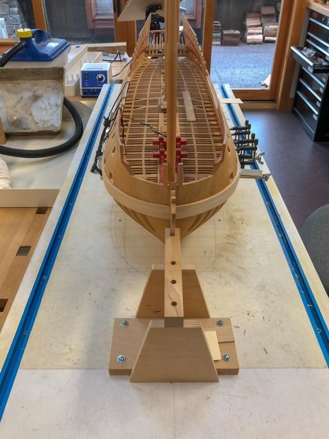
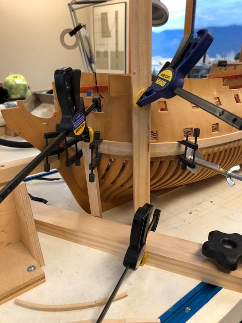
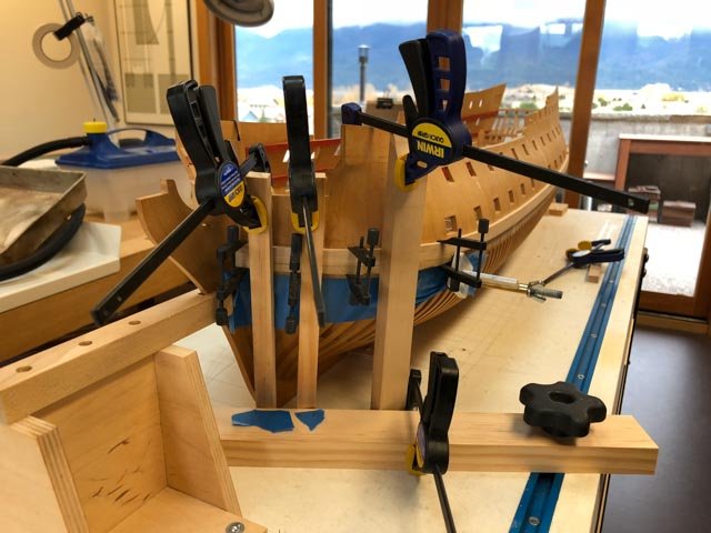
Back to the Bellona, I picked up where I left off, finishing the lower two strakes of the port wale. Too clever for my own good, I steamed the foremost two strakes together, thinking I could clamp them into the fixture at the same time. I pulled the long one out, and then discovered the shorter one had slid back in the steamer. By the time I fished it out, the first one had cooled to the point that when I tightened up the clamps on the fixture, I heard a loud crack. Missed my window of plasticity in the steamed wood, and had to make the two strakes all over. One always learns from mistakes; now I know how long that window is...
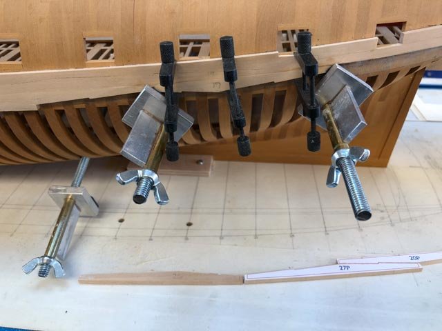
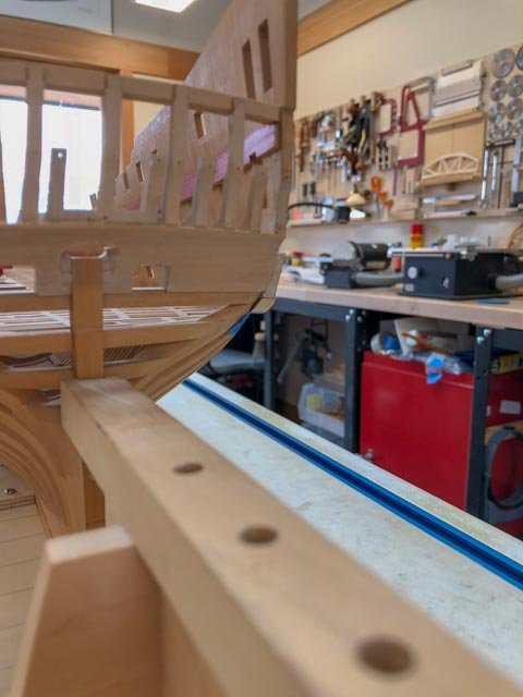
I did finally figure out how to clamp these lower strakes, which had given me so much trouble on the starboard side because I could not get a fore-aft clamp to them (the gundeck behind is in the way of a clamp). This time, I fastened a batten across the building board, and used this to restrain the feet of several vertical boards. When the tops were clamped against the hull, their middles pulled the wales snug against the hull.
I hope to make more progress this fall, now the snows are threatening.
Best wishes,
Mark

-
Hi Alan, thank you so much for following up on the rigging warrant. £420 for the 6 pages exceeds my retirement discretionary income, so I will have to wait until a hopefully cheaper digital copy comes out in the next year or so. I have a way to go before rigging seriously comes into my project, so the timing might work out OK. Do you know how I would find out if and when it is digitized?
druxey, that is fascinating to see, thank you. I had read about girdling (mostly in Patrick O'Brian books), but this is the first I have seen what that looks like. Presumably, this simply increases the girth of the hull, providing more lateral stability and less roll. It doesn't seem like a few inches would do much, but multiplied by the length, that is probably a lot of additional bouyancy at midships. I wish I understood more about the science of hull shapes.
Mark
-
Hi Mike, I look forward to hearing how things change for you at the larger scale. More opportunity for details, etc.
Mark
- mtaylor, Stuntflyer, FrankWouts and 2 others
-
5
-
-
-
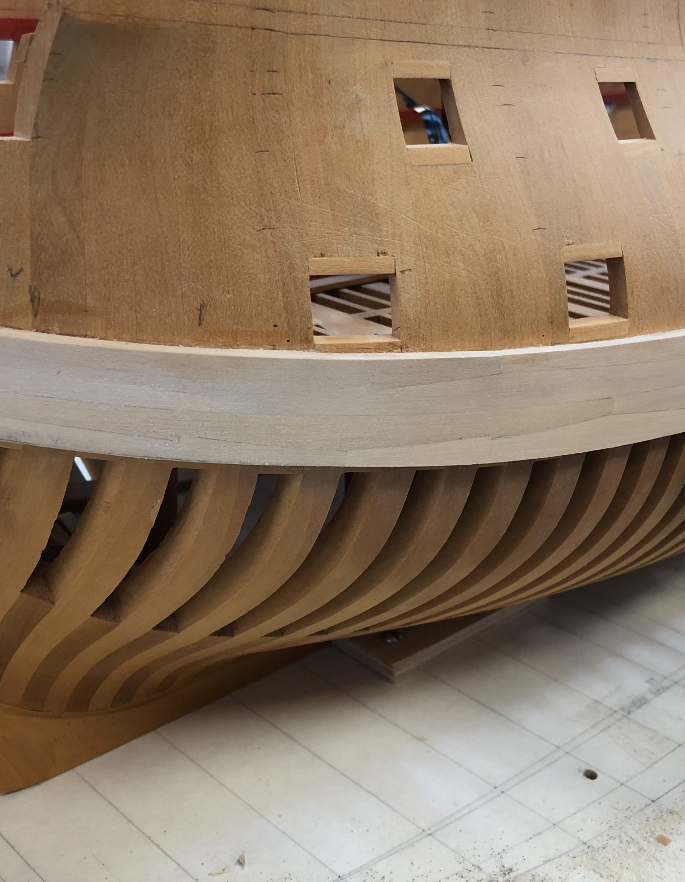
Thanks, druxey and Mark P, I think we have resolved how this complex junction is managed. The Bellona sheer drawing shows a larger radius curve at the lower, aft corner of the wale, and from the way things are lining up on the hull, I think it is because of the natural curve of the plank immediately below the wale. At least that is how it seems to be emerging as I try to fair these pieces.
druxey, I see your wale does tuck under at the lowest, aft corner; this is reassuring, because mine really looks like it wants to tuck under. Mark P's image shows a wale more straight up and down. I am sure this has entirely to do with the particular geometries of the under body for each ship.
The famous architect Lou Kahn once asked, "what do you want, brick?", to determine how to use it according to its own inherent nature. I would apply this to wales at this point: "wale, how do you want to follow the natural lines of your hull?" Apologies for weird thinking...
And by the way, beautiful model of the Resolution, druxey!
Mark

- mtaylor, aviaamator and albert
-
3
-
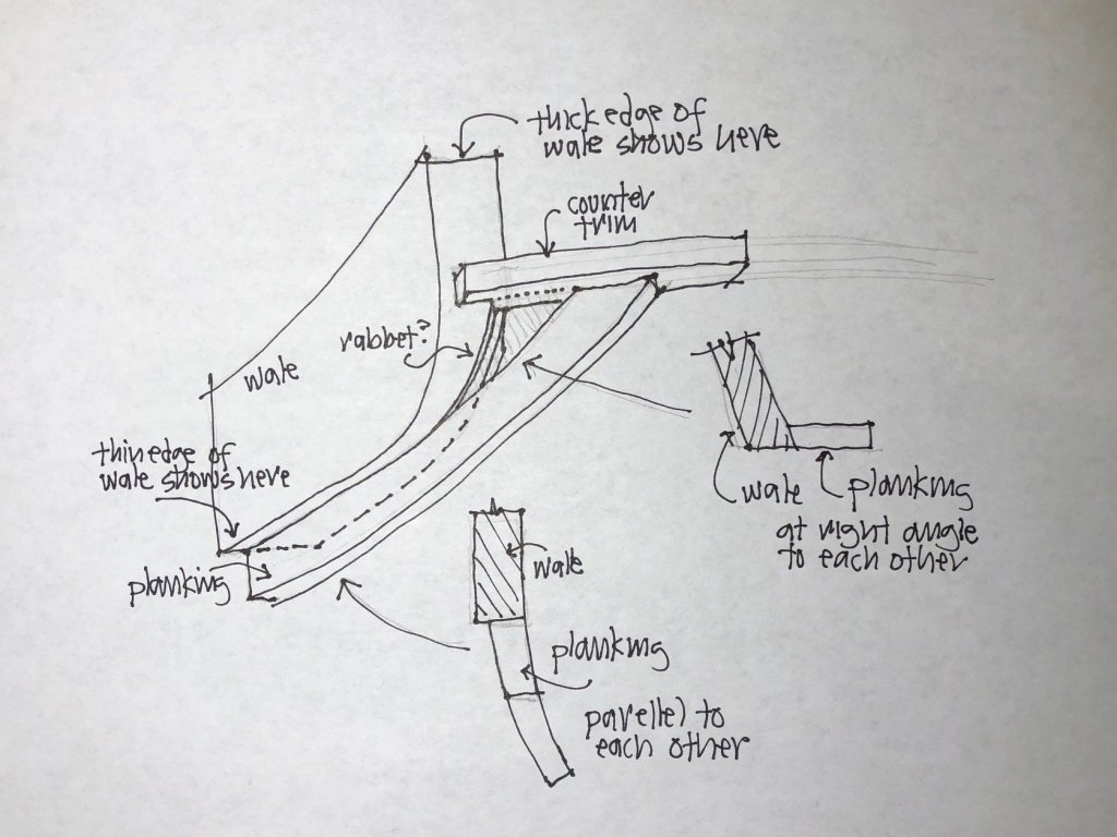
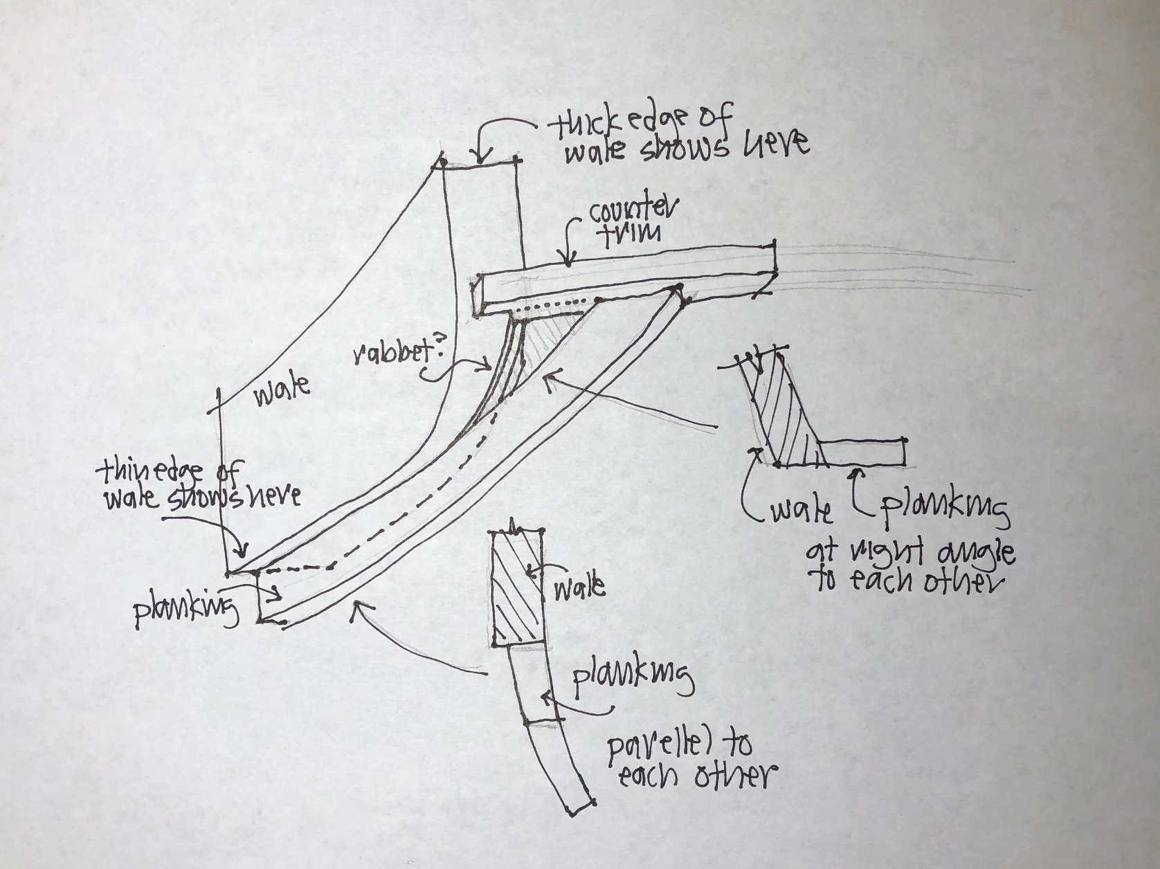
Thanks, Mark, this is a very helpful view. I think it confirms where my hull seems to be taking me. The wale is revealed at full thickness at the aftmost end where it is vertical and hits the lower counter, but shows only 3-4" along its lower edge where the lower planking is parallel to the wale and abutting against it.
The triangular plank we have been discussing looks like a transition piece, itself standing at right angles to the wale at the top, but allowing the lower planking to come from parallel to right angles to the wale as it bends around the corner.
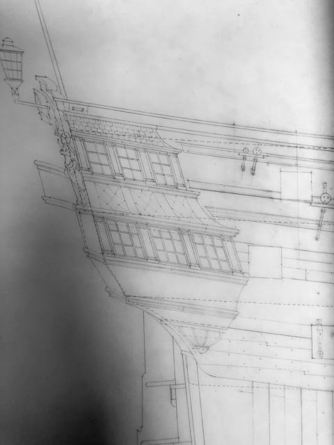
The attached drawing shows how perhaps a rabbet would provide a landing for the small triangular piece, where the rabbet would be narrow at the top and increasingly wide at the bottom. This is a difficult drawing to visualize; it tries to line up with the perspective of Mark P's image above.
This would be a fairly elegant solution to reconciling all of these at this corner, as best as one might expect given the complexities.
Mark
-
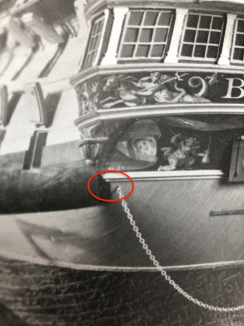
hi druxey,
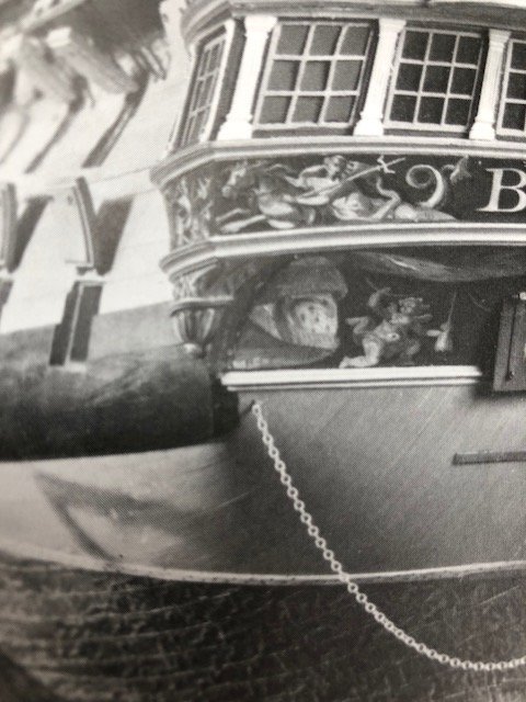
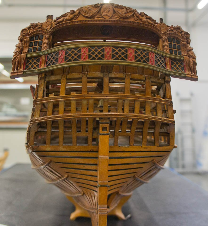
Well spotted, I never noticed that. Could it be the little corner of planking just above the chain circled in red below? If so, the wale in the first model has wrapped much further around the corner than in the second model. In the second model below, the triangular plank hits the inner side of a much thicker wale at an obtuse angle, and could not be confused for a smooth continuation of the wale plank as in the first model.
Mark
-
Just for fun, I looked again at the photos I took of the 1st Bellona model. It shows the lowest, aftmost plank of the wales curving around under the stern, like the planking presumably would do below it. This is not consistent with the original Admiralty sheer plan, nor with the 2nd Bellona model with the copper sheathing. I will have to assume that this was a modeler's convenience, dealing with the reality of skeletal planking in this portrayal of the ship. Unless anyone has seen a wale curve under the counter like this.
Mark

- Jeronimo, albert, paulsutcliffe and 2 others
-
5
-
Amalio,
Outstanding project, some of the very best craftsmanship I have seen. You are a source of inspiration!
Mark
- Obormotov, Amalio, Tigersteve and 1 other
-
4
-
Thanks, druxey, that confirms for me that I am on the right track. This is definitely a spot that is less than gracefully worked out, in the big scheme of design. I think a lot of fiddling had to go into reconciling the various parts that intersect here. I have noticed that on some other ships, the lower edge of the wales align exactly with the trim across the lower end of the counter, making the junctions below this easier to reconcile. Look at Siggi's nice junction at this spot, for example, on the 1745 Establishment ship.
But for some reason, the Bellona drops the wales partly below this, causing them to run partly into the counter, and partly into the very complex compound curves below. This has to be the point where the construction crew asks "what the [insert favorite explicative here] was the shipwright thinking here?"
Mark
- paulsutcliffe, gjdale and mtaylor
-
3
-
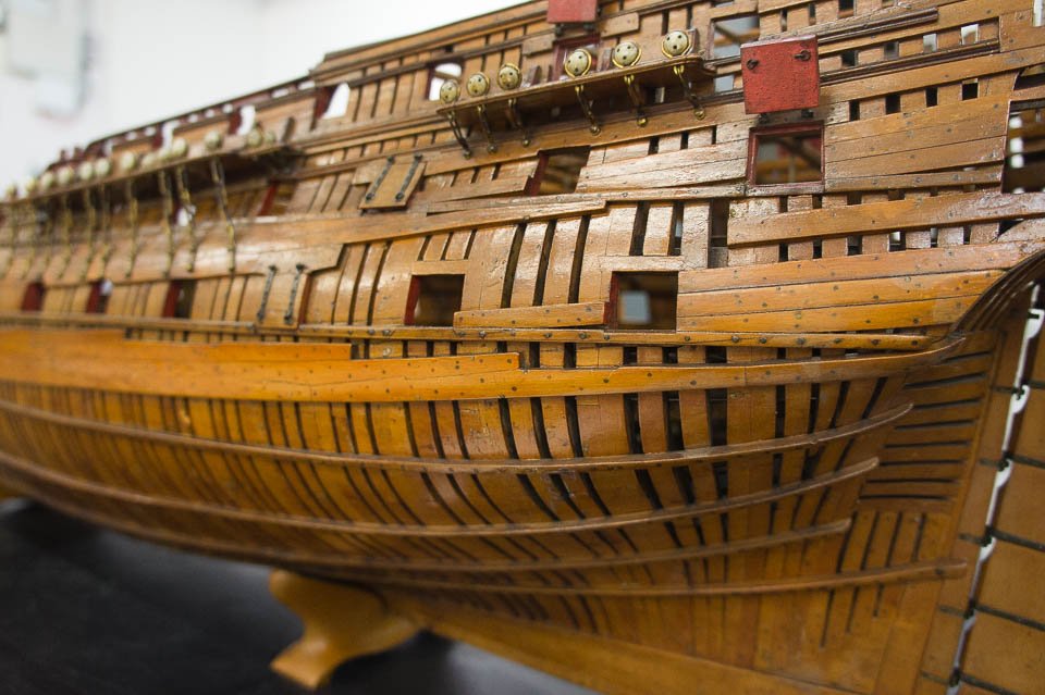
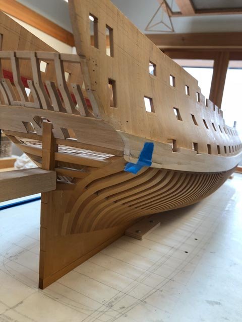
I spent a happy day carving the last plank. However, in trying to make everything fair together, I noticed that a gap appeared to be forming between the curved end of the wale (see the curve in the drawing below), and the hull framing itself. I thought I had messed up my framing somehow. But then I looked at the photo of the second Bellona model below, and noticed that the wale shows its full thickness along the counter and along that lower curve, but not on the lower edge. The planks are clearly coming around that curve, and then tucking in behind the wale at the curve itself. If this were not the case, the short little planks at the curve would be covering up 4 inches of the wale, which it does not appear to do.
So, I am assuming for now, until someone tells me otherwise, the wale does indeed stand away from the hull at that curve, enough for the lower hull planking to die into it. I have had a devil of a time visualizing what is going on at this junction...
Mark


- mtaylor, Mike Y, Captain Poison and 12 others
-
15
-
Thanks, Gary, for the comments. It is kind of hard to realize now, but I learned to draw before CAD was invented or at least used in architecture offices. I am a dinosaur! Gaetan, I haven't checked my family tree lately....🙂
It took pretty much all day, but I got the second to last plank in on the wales. It has a very sharp twist athwartships, and a good bend aft. I could not get a clamp on the end for love or money to steam it to shape. And I could not imagine a former that would deal with the springback accurately. So I fayed a double wedge shaped piece onto the inner surface, fitted it to the hull surface, and sanded down the outer surface to parallel. The join is on the under surface of the wale, where hopefully no one will ever look and the black stain will cover it (as long as none of you give away the secret).
The final piece is even worse, and I can't visualize yet exactly how it lands and what its aft edge looks like. The second Bellona model shows a sharp corner at the lower, aftmost edge (see photo), but the sheer drawing shows it gracefully rounded. I will put a big block against the location tomorrow and start carving until it looks right.
Mark
-
I will add to the other comments the same compliment: those sculptures are beautifully done!
Mark
- mtaylor, FrankWouts, DORIS and 5 others
-
8
HMS Bellona 1760 by SJSoane - Scale 1:64 - English 74-gun - as designed
in - Build logs for subjects built 1751 - 1800
Posted
Thanks Alex, I will try grinding down a cutting tool like yours, and have a go with the duplicator. I may have additional questions once I get started!
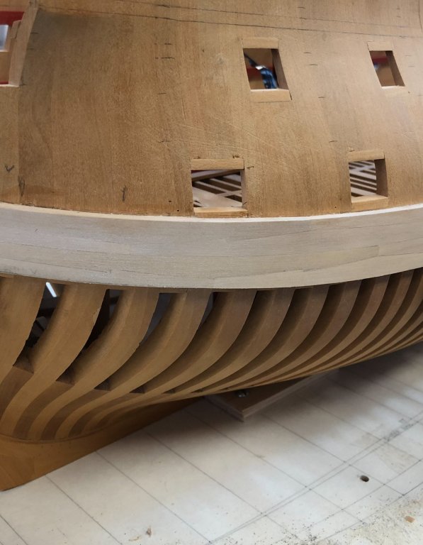
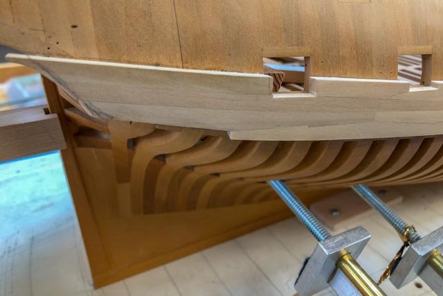
druxey, you really got me thinking about the deck. In the middle of the night, I suddenly wondered why many years ago I had rejected the idea of decking under the guns. I think at the time I wanted to show off all of the deck framing. But once I realized this will all be covered up with subsequent decks, I thought why not just build 5 strakes of decking under the guns and be done with it. I will have photos of the original framing to remind me what it looked like, and a solid deck is going to be a much better anchoring point for the guns. I do worry about them shifting around over the years to come, when it will be exceedingly difficult to get in and re-fix one in place if it comes adrift.
The first photo shows what it might look like, with the correct thickness of planks. The second photo shows that I have one plank left in the wales, before the carved one at the very aft end. This one also has a nasty bend, and I have had to fay a spacer on the end as I did on the starboard side. Should be done tomorrow!