


SJSoane
-
Posts
1,641 -
Joined
-
Last visited
Content Type
Profiles
Forums
Gallery
Events
Posts posted by SJSoane
-
-
Thanks, Joe, for your kind thoughts. Having just recently retired, I am enthusiastic about having more time in the shop, and yet I have an increasing awareness of more years behind me than in front of me. It helps keep me focused on making stuff as long as I can!
Mark
- paulsutcliffe, druxey and daHeld73
-
 3
3
-
-
Thanks, Jason. I have looked at those photos for years, and I always assumed the stem was the same as the wales, and the bluish tint was just a different light falling on the black vertical surface. It does appear now to be the same blue as is seen behind the friezes.
- daHeld73, mtaylor and paulsutcliffe
-
3
-
Last night I was looking at various images I have of the Bellona's bow, and suddenly realized that the paint on the stem is dark blue, not the black of the wales. This changes everything! I will need to paint the blue with opaque acrylic paint for the friezes, and I can do the same for the stem. So I can cut in a clean line with paint, rather than staining black and worrying about the stain running.
It never hurts to look at the sources again...


- mtaylor, aviaamator, paulsutcliffe and 3 others
-
6
-
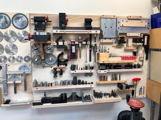
I mounted my lathe and mill on laminate MDF as Doug just showed; nice surface for cleaning up. And after previously experimenting with tools in drawers, I more recently tried mounting them all on the wall, where I could see them all. I prefer this method now.
Mark
- aviaamator, KeithAug, Jim Rogers and 10 others
-
13
-
-
-
Hubac'sHistorian, that is worth trying; I will experiment with that, including the idea of using an airbrush. With good masking and the hull turned upside down, an airbrush might do the trick.
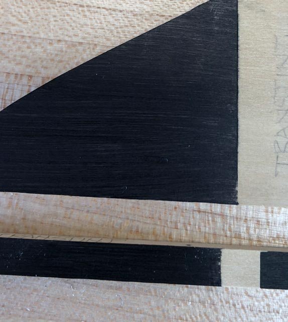
Meanwhile, I tried two other finishes, that are getting closer, but not quite yet.
I scribed very deep lines with a scalpel, which seemed to help. Then I taped with Tamiya tape burnished down.
The one on the upper left and lower left are both Transtint black dye mixed into General Finishes gel topcoat wipe on urethane, which is my main finish for the natural wood. This was put on with a rag.
The one on the lower right is the Speedball black ink used by Ed Tosti for his Naiad project. I used a paint brush. In another test, the Speedball also ran, so I am not sure why I got such a clean line on this experiment. Before risking the entire hull, I will play with these a little more until I get reliable results every time.
Best wishes,
Mark
- mtaylor and paulsutcliffe
-
2
-
I echo Ed's comment. Beautiful project.
Mark
- aviaamator, mtaylor and albert
-
3
-
Thanks for the likes, and thank you Paul and Albert for your kind comments.
Thanks Greg and druxey, for thoughts on the staining/painting issue. I don't think I will have problems on the wales on the upper side, because I can paint/stain before installing the black strake, so I can get a clean line there. And the lower side I think I can cut in with masking tape and an incision, because the wales are physically a separate piece from the hull. I take your point, Greg, about errant stain; I will probably turn the hull upside down and mask the entire thing except the wales before commencing.
The challenge is on the stem itself, where the paint edge simply stops on the same surface as seen in the Bellona photo above.
I looked back at Alex M.'s terrific Sphinx project, reminded again what an outstanding project that was. He reported that he used acrylic paint for the wales, which would make sense for the predicament I find myself in. Undiluted paint would sit on the surface, and allow a sharp edge to be cut in, whereas diluted paint and stains soak in and run along the grains past the tape. The problem with paint is that it will cover up the wood grain. The Bellona model looked painted, not stained, and perhaps I need to get used to this idea for my model. Or maybe I can work a way to cut in an edge with paint, and then stain up to the paint.
I think I will have the same challenge when it comes to painting the gun port stops in red; I had been hoping to use my red stain, and may have to consider paint.
I will try a few more experiments and see what I can come up with.
Best wishes,
Mark
- mtaylor, daHeld73, Hubac's Historian and 1 other
-
4
-
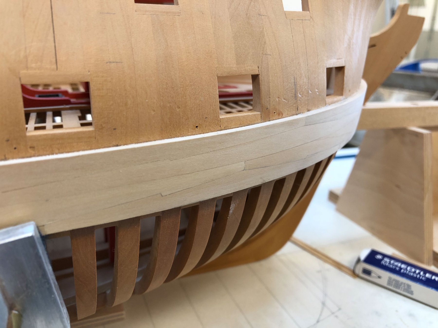
Thanks, everyone, for the likes. And thanks, druxey, I may try upside down when I get to the multiple twist stern planks. For now, the straight side is going quickly--at least as quickly as I seem to be able to work. As I move along, I am scribing the lower edge relative to the top edge with a compass, to ensure parallel edges. I am trying to sand these lower surfaces to the correct size before attaching, because I need to protect the hull surface below which will always be exposed; no lower planking for me!
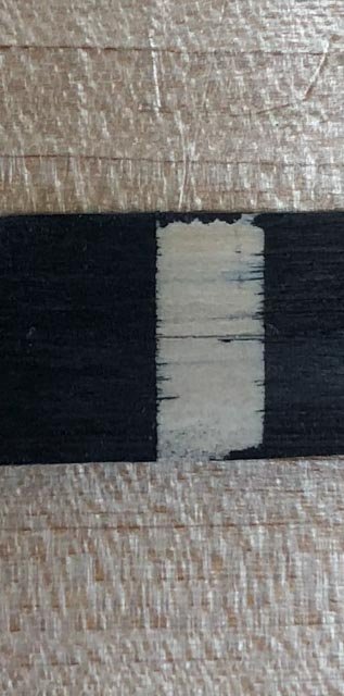
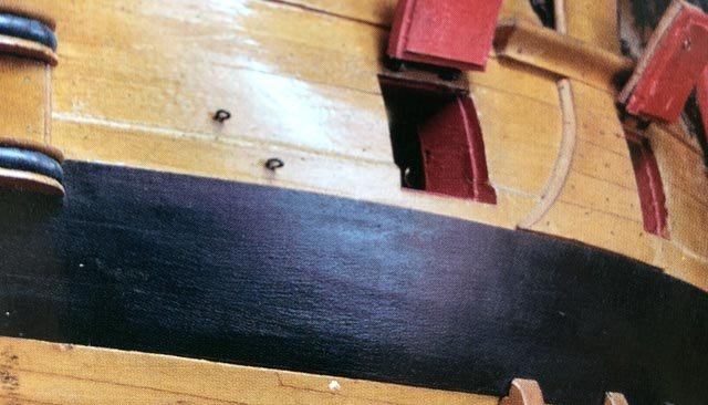
I tried a sample of blackening using Fiebing's black shoe polish. However, I see I have a problem cutting a clean line as I will need to do on the stem pieces, as seen on the 2nd Bellona model below. On my sample, I used Tamiya model tape pressed down with a burnisher to make an edge; on the left side, I also scored the wood with a scalpel, I thought fairly deep. But both sides let stain run past the edge. Any thoughts on how to cut a clean edge using the shoe polish?
I pulled out some samples I made a number of years ago, using Floquil flat black diluted to act more as a stain. It also ran under the masking tape. I will try Ed's Speedball ink next, but I suspect that since it is also watery, I will have the same problem. I don't want to point fingers, but look at the wiggly line painted on the Bellona model...
Mark

- Wintergreen, Jack12477, KORTES and 16 others
-
19
-
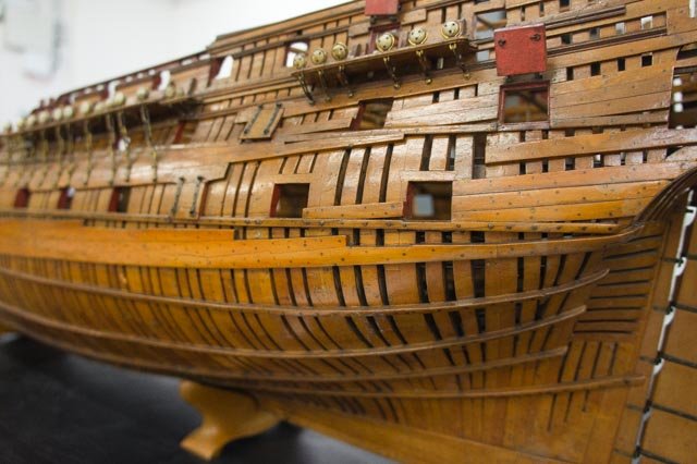
Your loving restoration is really showing the beauty of the model!
Mark
-
Hi Michael, thanks so much for the nice comments. And thanks, druxey, for guidance on the black strake.
Work proceeds on the lower two strakes. These have proven to be more difficult than I expected, more difficult than the upper strakes. Perhaps because the hull begins to curve inwards at the lower level, combined with the challenges of clamping that low down and on the curve of the bow. I reached the flat section, and hope to pick up the pace before hitting the challenging stern section.
Best wishes,
Mark
-
Michael,
Looking great! What are those short railings along the lower deck? Is it more obvious once the lifeboats are installed?
Mark
-
Russ, what were those hatch covers made of in the real ship?
Mark
-
-
Thanks, everyone, this is beginning to converge on what seems to make the most sense.
I will assume the Bellona scantlings were at the thinner end of these ranges, since everything seemed to grow larger towards the end of the eighteenth century. The scantlings for 80 gun ships in the 1719 and 1750 Establishments most closely match many other sizes for the Bellona 74 that I have been able to verify from other sources, so I will assume the 6 ½" for the thickness of the black strake as set forth in the Establishments and further stated by the Ship's Repository a few decades later. Looking at the fully planked Bellona model, this was of a constant thickness, although it does seem to have a rounded upper surface as seen at the gunport. And the later sources and the Bellona model appear to call for a 1'-0" width (plus ½" in some sources), close enough for me at 3/16" scale.
In most of the primary sources that call for a second plank above this, they specify a plank 1" thinner than the wale, or 5 ½" in this case, wearing off to the 4" planks above. But this does not appear to be the case in the Bellona model itself. The difference in thickness between the black strake shown in the model, and the planking directly above it, looks to be more like 2" --since the planking above is 4", this exact difference would be 2 ½". And so there appears to be no special second plank above the single black strake with its rounded top, just the normal 4" planking.
Given this, I am inclined to follow druxey's lead here, and use a single strake, not painted, 6 ½" X 1'-0", with a rounded top.
So why would the Bellona model use only one black strake, as called for in the Establishments that finished in 1750, and not two strakes, as called for in all of the sources and all of the contracts for individual ships a few decades later? I will assume that the experimental Bellona design in 1758, the first 74 in the British navy, drew upon the last Establishment revision of 1750 for most or all of its scantlings. As best I can tell, the old 80 gun ship in the Establishment was about the same overall size of the new 74; so why not use the well-tested scantlings for a ship of that size? The creative energy would have gone into changes in deck and gun layouts to convert from an 80 to a 74 of the same size, not changing the fundamental fabric of the structure.
And of course the later 74s following in the footsteps of the Bellona grew increasingly larger; and so a few decades later, their scantlings would have likewise grown.
Interesting that an additional transitional strake above the black strake creeps in over the next few decades. I have no idea for explaining this evolution!
Druxey, did you round the top of your black strake, like in the Bellona model?
Mark
- dvm27, daHeld73, paulsutcliffe and 2 others
-
5
-
As I wait for planks to dry after steaming, I started looking at the black strake again. Since the Bellona was a transitional ship designed in 1758, between the earlier Establishments (finishing in 1750) and the later consolidations reflected in Steel (1805) and the Repository (1788), the scantlings are not easily confirmed. Here are the data points on either side of the Bellona's time:
Only establishment shown in Allan Yedlinsky's book is for 1719 for an 80 gun ship--because the Bellona was the first 74-- (blank for 1745 and 1750 because presumably the same): "One strake above [the wales] 6 ½" thick." (and no width specified).
Steel: 2 strakes, one 7" X 1'-1 ½", the other 6" X 1'-0".
Repository: 2 strakes, one 6 ½" X 1'-0", the other 5 ¼" X 1'-0".
Brian Lavery's book on the Bellona calls for 2 strakes, 6 ¾" reduced to 5 ½", but this has no reference to a primary source.
My own photo of the Bellona first model does not seem to show a black strake (at the stern, the wale is showing 5 strakes rather than the specified 4, so the partial upper one must be the black strake but it is the same thickness of the rest of the wale; not helpful).
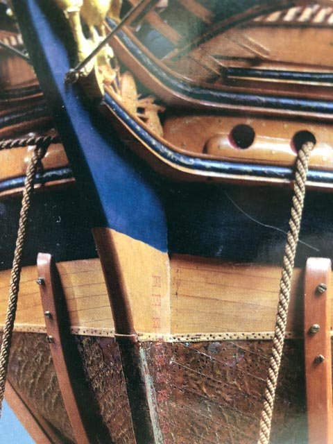
Very compelling is the photo of the second Bellona model, shown on Lavery's Ships of the Line cover (see photo below). It appears to show only one strake thinner than the wale but thicker than the planking above, and compared to the width of the wale (4'-3"), this black strake appears to be about 1'-0", the width of individual strakes called out in Steel and the Repository.
And then there is the very good discussion on Gary Shipwright's build log with Gary and druxey (page 14 in the link below), which suggests that there is an additional strake above this one, that tapers from the black strake to the planking above. Assuming the lower strake is 6 ½" thick and not tapered, and the planking above is 4" plank, then the second black strake would be 5 ½" tapering to 4". At 3/16" scale this will be very subtle!
Mark
- Jack12477, daHeld73, paulsutcliffe and 6 others
-
9
-
-
I further recommend the Tamiya tape. Used that a lot building plastic models with my son years ago, and it has transferred nicely to wood projects.
Mark
- mtaylor, russ and popeye the sailor
-
3
-
And thanks, Hubac'sHistorian. The mountain view makes up for the remoteness. And the long winters provide more inside time in the shop!
- mtaylor and paulsutcliffe
-
2
-
-
Hi everyone,
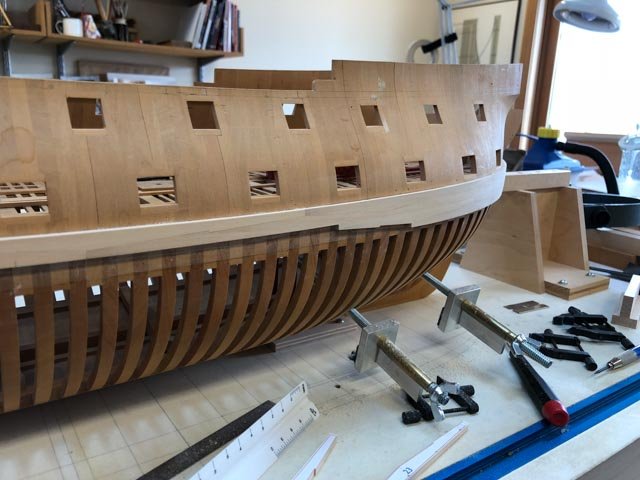
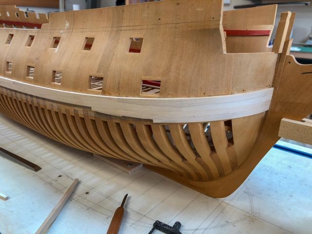
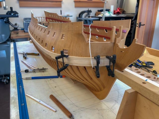
Thank you, everyone, for the helpful suggestions. It turns out that it was spiled accurately but it had the opposite of spring-back from the steaming and bending; it was bent a trifle too much, so the middle was sitting about a 1/16" away from the hull in the longitudinal direction while the ends were touching the hull. Finger pressure was enough to get it in place.
So after trying a number of failed clamping ideas, I went with Greg's suggestion to use spots of cyano in between the carpenter's glue. After experimenting with a few spare pieces, I just went for it. It took rather longer than 90 seconds to grab, and I was able to get some vertical clamps in. And all held well. Nice to have that behind me, and I learned a new good trick.
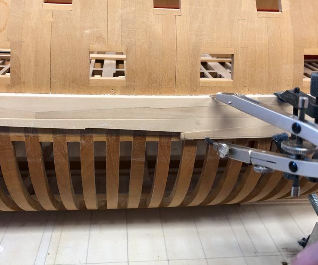
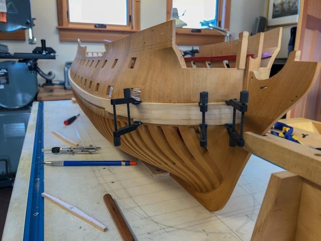
I also took off the batten, because my clamps are too short to span the entire wale plus the batten. Without the batten, you can begin to see the true lines, as in the second photo.
Mark
-
After more careful fitting of the lowest, foremost plank, it bows in the center, keeping the two ends tight against the hull if I can just pull the center tight to the hull by about 1/16". I am contemplating a Spanish windlass, using a cord I managed to thread under the gundeck to a point on the port side opposite the line of force needed. If I smoked, I would smoke a pipe now while contemplating whether this would distort my hull or put creases in the hull where the cord is pulling tight. Since I don't smoke, I will try gently tightening to see whether things start creaking or not.
Mark
HMS Bellona 1760 by SJSoane - Scale 1:64 - English 74-gun - as designed
in - Build logs for subjects built 1751 - 1800
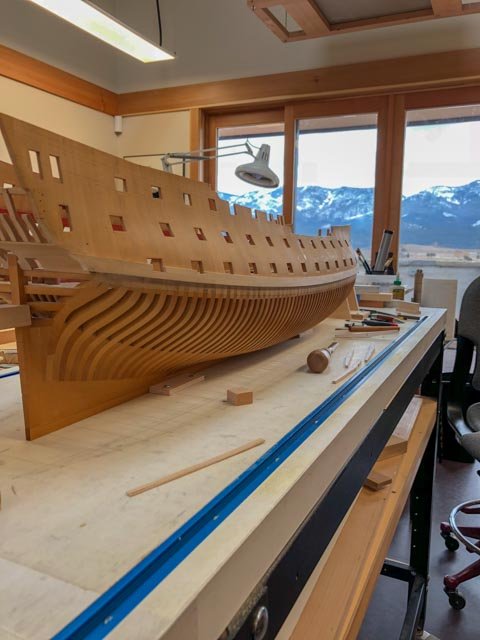
Posted
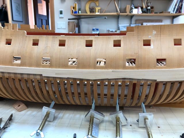
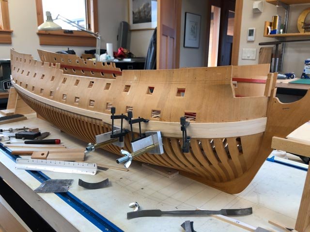
Work proceeds on the starboard wales, with only three planks--the most twisty of all--to go. While the uppermost one is steamed and clamped against the hull waiting to dry, here is an update.
I have decided to mock up a single gunport and adjacent wales, to see how I am going to manage controlling the red stain around the port, against the plain external planking and the black wales. Like the black wales, I am concerned about the red stain around the gunports running into the grain of the adjacent planks, and only a test will tell me.
I did have a little more success using the Transtint black dye mixed into the urethane clear finish. Rather than dealing with a watery liquid like shoe dye or ink, this allows me to pad on a tinted gel. And it has the same level of matt as the uncolored finish.
I will also experiment with airbrushing the blue acrylic paint onto the stem, and also onto the upper works where the friezes will go. That should help me keep a clean line. I am thinking about ordering the Caldercraft Admiralty paint "French Blue", unless someone has had a bad experience with this paint, or thinks it is not the right color. They are supposed to match the colors around Nelson's time, which is almost a half century after the Bellona; I can only assume the blue color would not have changed, for lack of any further evidence. I have only the second Bellona model to go on, for a match.
Mark