


SJSoane
-
Posts
1,641 -
Joined
-
Last visited
Content Type
Profiles
Forums
Gallery
Events
Posts posted by SJSoane
-
-
Håkan,
Nice story about your real boat.
I have always marveled at how clinker built hulls can be shaped without ribs. You are demonstrating well the complexities involved in this construction method.
It really does rely on the "eye" of the shipwright, doesn't it?
Mark
-
Hi Siggi,
I see your dilemma. I never looked very carefully at the wales with two separated black strakes, because they were before the time of my ship. I cannot see the joint in the first example you showed, which is the condition you are constructing. Are there any other examples you have in your great collection of photos that you could show here?
I would assume that the three strakes are indeed separate from each other, not hooked to each other. Why call it out as wales and stuff between, and then paint the three strips separately, if the joints in the underlying construction are not three separate, continuous lines? Anchor stock or butt and hook would obviously have the joint line wavering up and down, crossing back and forth across the paint line. This does not seem logical.
If this is the case, then the hooked joints called for in the establishment would only apply to a single strake's planks connected together horizontally. I would assume the joint would be like the first or third sketch, since the second does not have a hook. I assume it would be like the third sketch, only because the Bellona's wales a few decades later put the hook in the center of the scarph, not offset like your first sketch. I would assume the later joint in the Bellona evolved from the earlier one you are trying to understand.
But this is all speculation on my part. I look forward to seeing how you resolve this!
Best wishes,
Mark
-
Thanks, John, your comment means a great deal to me.
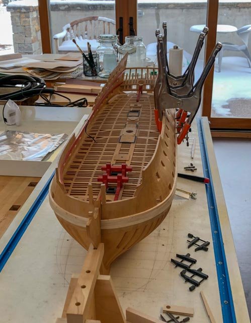
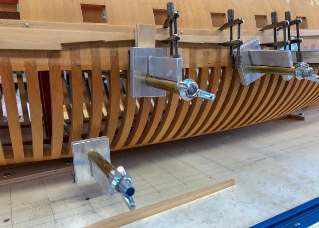
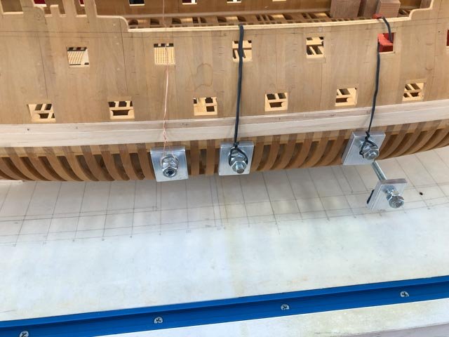
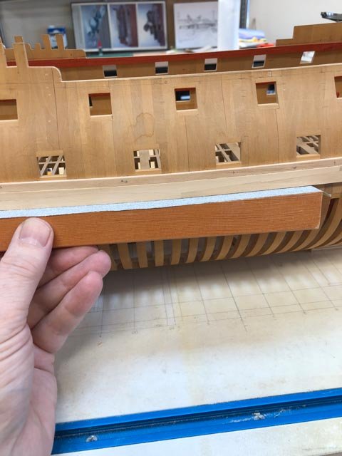
Work proceeds on the port wales, using the old clamps at midships to grab from below where the deck is too high relative to the wale for a clamp from above. The second photo shows hanging the clamps on the starboard side to keep them level when tightening.
And a view of both wales from the bow, although the lower two strakes are not yet installed and the battens are not yet removed.
Mark
-
-
-
Hi druxey,
I tapered the plank down to about 1 ½" oversize at the rabbet, leaving room for some leveling. The temporary batten above the wales is not tapered, and is blocking our view of the tapered plank below in these photos. Incidentally, this was also causing me some problems in seeing if the plank was truly clamped tight at this point, one of the reasons I made the custom clamping block to ensure a tight fit. Next time I should taper the batten as well.
And thanks for checking. It is easy to lose track of details in these complex, multi-step phases. I forgot to trim the length of the first plank before I steamed it, and so had to pare it back while holding the curved surface steady on a cutting block. Would have been easier if I had done it when the piece was flat.
It was thrilling to see all of the teams march into the Olympic stadium last night. Young people all over the world united in a common cause of attempting to achieve their very best! And there was a ship and a boat....
Best wishes,
Mark
-
Thank you, Gary, druxey and Håkan for your kind comments. It helps me keep going.
druxey, thank you for confirming that I should work on the port side top two strakes, before going back to the starboard lower two strakes. I want to trap the frame on both sides as close to the same time as possible, when the humidity is roughly the same. I worry about unequal pull on the two sides if one is restrained and the other is not when the humidity changes.
Last time, I fiddled with a variety of clamps at the bow. This time, I fashioned a wooden block that can be clamped against the bow by way of the back of the stem. It provides a good, clean, simple way of clamping. I need to take the time to make special clamps like this in the future; worth the extra time for a clean assembly process.
I also experimented with steaming and clamping the top plank on the port side directly to the hull, not to my former. The next day, the spring-back was so great that I steamed the piece again and clamped it in the former, now upside down, to make the piece symmetrical to the starboard piece. It now lays nicely against the hull.
Time to watch the Olympics!
Mark

-
Hi Alan,
I would either use a small adjustable bevel, or a card template (old manila file folders work well), to obtain the correct angle from the hull. Then you can transfer this to the cill to give you a pretty close idea of the angle you need to cut on the end of the cill.
I then use the following method for refining the first cut. Putting graphite paper between two surfaces you are trying to join or fair, squeezing tight, and pulling the paper out, gives a very clear indication of high points needing filing or sanding.Sometimes I use small files to remove the high spots. Sometimes it is easier to use sandpaper mounted on a 12" X 12" piece of plywood with 220 and 320 grit sandpaper spray mounted to it on either side. You gently slide small pieces of wood against this sandpaper to make small adjustments to sizes and angles. The advantage of moving the piece against a stationary sanding surface is that you are less likely to round the corners or edges as long as you keep "feeling" the flat of the wood. If you are having to adjust the bevel slightly, put pencil graphite on the surface and tilt the surface slightly for the first few passes, and then check to see if you are evening sanding the new adjusted bevel.
I find I can creep up on a fit very precisely this way, although it can be tedious. It is check and file, check and file, numerous times.
Your build is looking great!
Best wishes,
Mark
-
Hi Siggi,
It is great to see your new project. The figurehead is spectacular! I wish you could give a class on miniature wood carving.
I look forward to your progress on this very interesting and unusual ship.
Best wishes,
Mark
- CaptainSteve, mtaylor and Siggi52
-
 3
3
-
Hi Gary and druxey,
Here is the details of the drawing of the black strake from Brian Lavery's Bellona book ( p. 42).
number 10 is the wale, and 13 the black strake. It shows a distinct step between the two strakes of the black strake, but from what I see everywhere else, and from your contract, Gary, I am thinking that the two black strakes would form a single tapered surface on the outer side.
Best wishes,
Mark

- aviaamator, Mike Y and mtaylor
-
3
-
Thank you, Alan and Mike, for encouraging incremental posts on the wales construction. Here is the next phase.
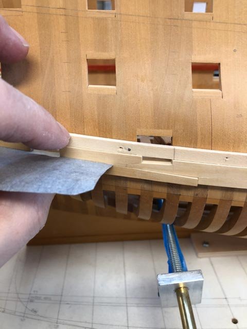
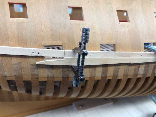
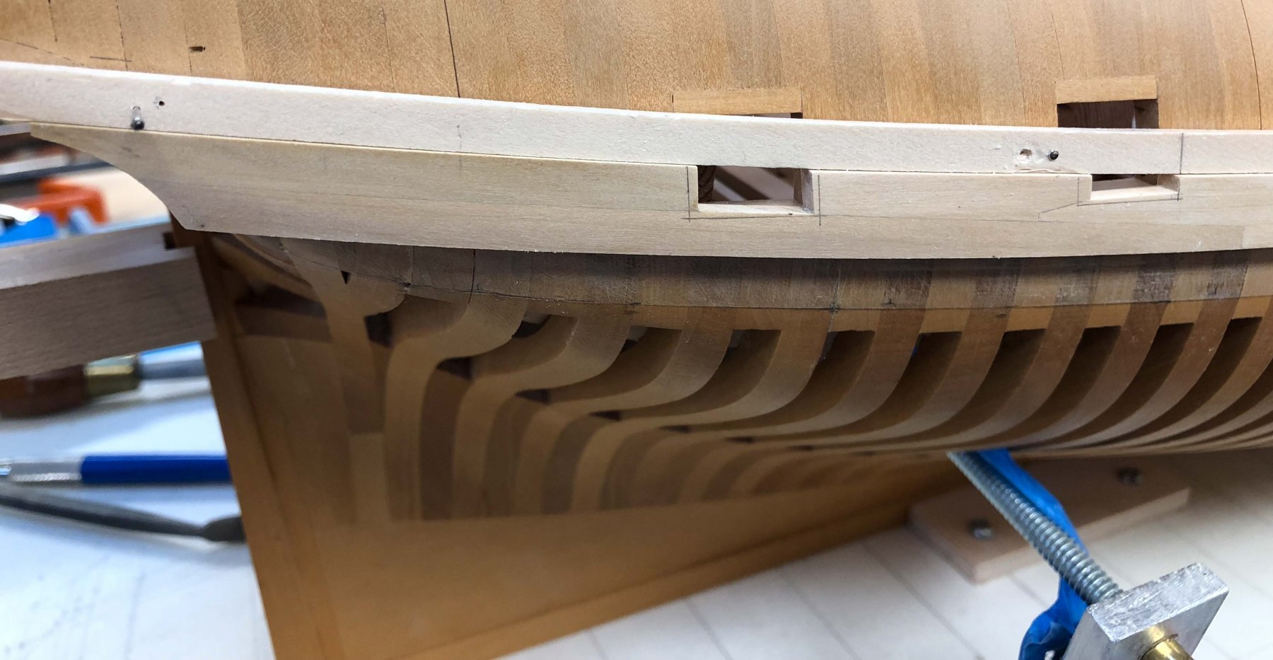
The sternmost planks of the wales were more challenging than I had expected, with the wicked twist to the stern counter. I haven't followed up on using a heat gun for bending, so had to wait overnight a few times for the steam bending to dry. I used artists' graphite paper to fit one plank to another. Squeeze the joint together with the paper in between, pull the paper through, and it shows highlights that need to be filed or sanded down. The last hi res photos shows how accurate this can be (thanks, Greg, for encouraging me into the occasional hi res photo). I also made long sanding sticks shaped to the curve of the wales (first photo), which help even up the lower edge ready for the next strake below.
I can see that sanding the wale to the counter is going to be challenging, avoiding accidentally marring the finished counter surface. I will leave these a little proud and turn the hull upside down for final shaping when both full wales are in. I can't see clearly enough what is happening with filing when the hull is upright.
I think I had better start on the port side before tackling the lower two strakes on the starboard side, just in case I start getting differential pull between the now constrained starboard side and the still unconstrained port side as the humidity changes.
Mark


- Mike Y, DORIS, garyshipwright and 15 others
-
18
-
Hi Gary,
As I look ahead a step on the Bellona, I noticed that Brian Lavery's book in the ship calls for two black strakes above the main wales, reducing, he notes, from 6 ¾" to 5 ½" with a step between them. But every other source I can find, including your Alfred build, shows just one black strake. Can you point me to a source for the size of the black strake as you researched it?
Best wishes,
Mark
-
Gary,
Worth the wait. The Alfred is looking terrific!
I swear by your batten idea for aligning major planking. It helps spot where lines are not quite sweet, and I don't know how I would have aligned the wales without this. Your photos show how well this is working for the Alfred.
And the cheeks dramatically add to the character at the bow. I am sure they must have been pretty fussy to install, particularly the upper one with a scarph in the middle of a change in direction for the curve. Nicely done.
Mark
- MEDDO, mtaylor and Hubac's Historian
-
3
-
-
Hi Alan,
Looking nice! I remember just how slow it felt to be gluing on one frame after another, and the length of the hull looked so long in the unfinished part. The center frames were most tedious for me, because the shape was not changing much to make it interesting. And my frames were much less work than yours! It did seem to speed up towards the end, perhaps because one could sense that the end was near...
Mark
-
Aha, that is pretty affordable. I'll see what I might do in this regard. The steaming and waiting 24 hours is getting tedious, even though I am retired and in no rush. Looks like welding gloves might be a good idea.
Mark
- mtaylor, michael mott, daHeld73 and 2 others
-
5
-
Hi Greg,
Yes, I removed the pads on the clamps to get maximum opening, and it just, just fit. My bigger clamp would have crunched the hull.
That is an impressive twist! Michael was also talking about hot air guns, and I had hoped Santa might bring one at Christmas, but alas no. Which one are you using?
So do you shape this over the hull while blowing hot air, or do you bend off the hull and periodically check for fit?
Mark
-
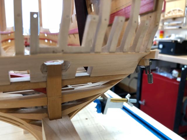
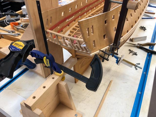
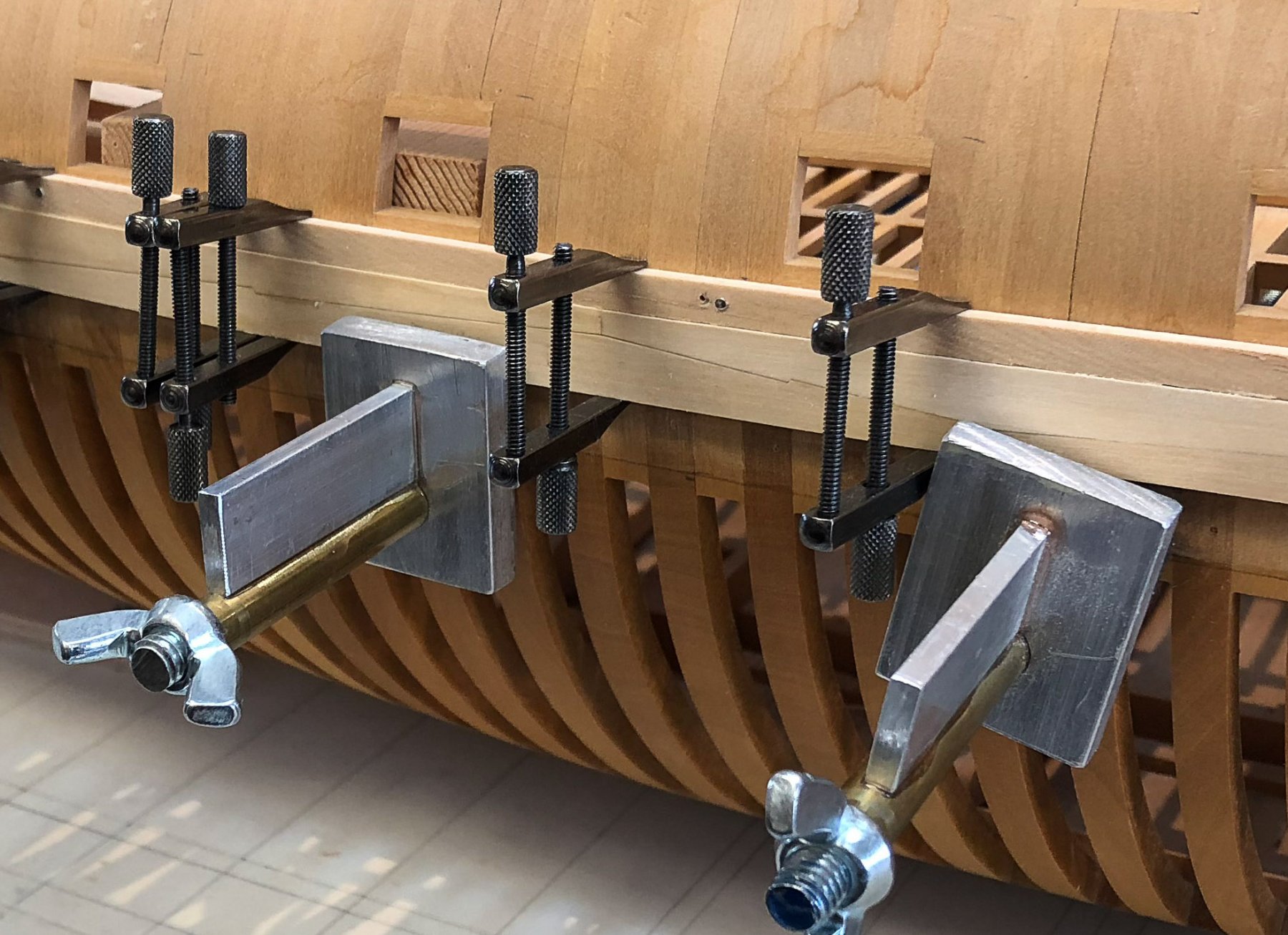
I apologize in advance if my incremental postings on installing the wales are getting too tedious. When I looked around for information on installing wales, there were many unanswered questions on some of these details. So in the spirit of helping others see some of the issues involved as I work through them, here is another unexpected one.
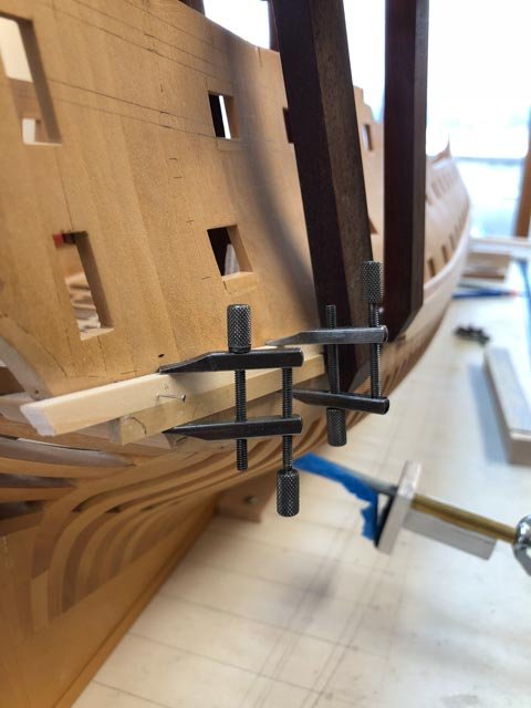
The top plank at the stern takes a fair twist in the vertical direction, in addition to the curve in the horizontal direction. I intended to steam and clamp the top two planks, and then follow David Antscherl's advice in the Fully Framed Model to carve the lowest 2 strakes to fit the very wicked curve further down.
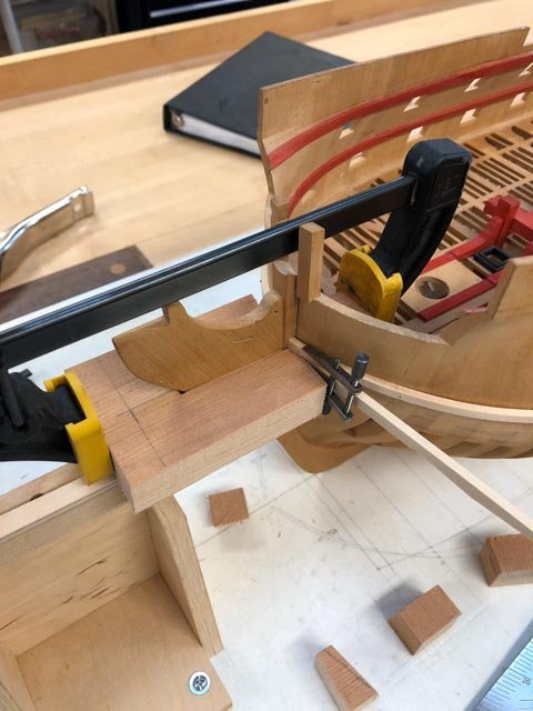
Then I discovered the problem of how to clamp the upper planks, first for steaming, and then for gluing. Clamps from the top or bottom cannot reach the plank, and a clamp across the stern slips off due to the extreme curvature of the sides. So in the best traditions of Rube Goldberg, I clamped a right angle device to the table, which gave a surface parallel to the keel to clamp to on the left. I then had to place a small clamp on the device holding the sternpost, to keep the horizontal clamp from slipping away on the right.
It is holding the piece in place after steaming; tomorrow I will find out if this will also work for gluing the piece on.
I realized that this pulled the hull out of true on the table top, and it will have to be re-leveled before I start marking up for subsequent work on the hull.
Mark
- AON, DORIS, paulsutcliffe and 11 others
-
14
-
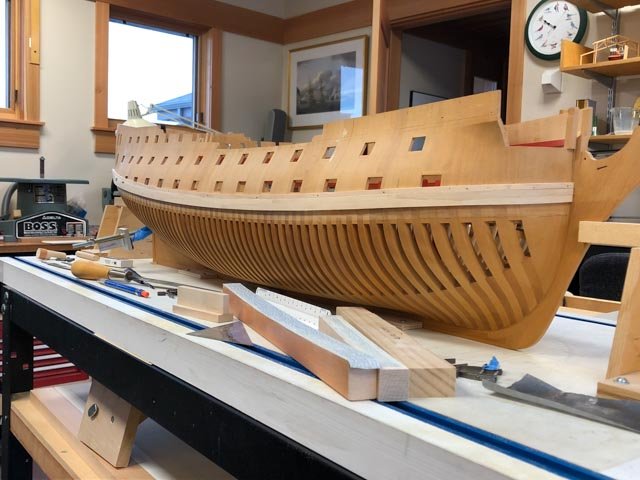
Hi John, Marc, yes, this model of the Bellona is absolutely captivating. I have studied photos of it for years, had a chance to examine it close up, and it still sings to me after all these years. The the lines of the ship, the exposed methods of construction, the assured craftsmanship of the model and its 250 year old patina, make this a timeless classic.
As best I understand from the various Brian Lavery writings about this model, it was likely used as a demonstration or study for some proposed changes in the hull framing system. One side is framed in a conventional way, and the other side proposes a potentially stronger but more expensive way to run frames from keel to top with fewer interruptions. One side is partially planked, the other has no planking.
druxey can probably give you a better understanding of the ribbands, the thin bands running longitudinally. They were removed as planking proceeded up the hull, and were initially used to align and fair the frames. Ed Tosti's books on the Naiad frigate illustrate how useful these were for keeping the hull together and aligned before the more permanent longitudinal structural pieces like wales, spirketting, deck clamps, planking, etc., finally locked everything together.
It is interesting in the Bellona model that parts of planking are inserted between the ribbands, since these would not have been in the same place at the same time in the actual construction. I supppose they needed the ribbands to hold the model together, but wanted to suggest the actual lines of planking on one side while primarily concentrating on showing the framing system.
I did not concern myself with ribbands on my model, because the stylized admiralty or dockyard framing system locks the frames together with no spaces between. This causes expansion and contraction problems with humidity changes, as I discussed earlier, but it does away with the need for ribbands.
Best wishes,
Mark
-
Hi Gary,
Your idea of battens is brilliant. It helps see the curve better than any other idea I tried, it provides a solid surface to check the upper curve of the planks against while sanding them to a final shape, and a firm clamping surface for the final installation. I will definitely use this idea for the upper works.
Hi res photos are uncomfortable; I admire Ed even more for posting these all the time. They show more than the eyes can see, and they reveal that one's craftsmanship is not as good as one thought. A little humbling. Maybe I can figured out a resolution for photos that exactly matches the level of detail that I can see without magnification...
Looking forward to seeing your progress on the Alfred!
Mark
-
-
Hi druxey,
A few years ago in Denver, I put a humidifier in the shop and it didn't seem to make a huge difference. But I did manage to start rust on tools, so I quit. Moving to Montana certainly has helped with higher humidity. Maybe the Admiralty models did not have this problem because it is more reliably damp in London more of the time.🙂
My posted picture raises a new question that I have not yet faced on this project. This plank is cut by the gunport. I started filing to fit before installation, and then it occurred to me that I ought to be using the gunport itself as a guide for filing the piece to final fit after it is glued in. This will be the same situation with all of the planking when it hits the sides of the ports. Are there any best practices for filing to the port without accidentally filing the side of the port itself? Masking tape on the inside faces of the ports?
Mark
-
Hi Greg,
I am like an aging film star; no closeups, soft filters on the lens required!
But in a Hollywood-like expose, here to reveal all, is a closeup of the plank I just glued one, before sanding. You can see all my dark secrets. The re-drilling of the temporary batten, the stain on the hull that has been there for 10 years and I have no idea where it came from, and most important, the seams opening up between frames in places.
These seams open up in the winter, with the lower humidity, and close in the summer. This is a classic problem of cross grain construction, where the wood expands and contracts much more at right angles to the grain than it does lengthwise. I measured this seasonal change at 3/16" to ¼" over the length of the hull. Good wood construction argues for avoiding this, or using slotted screw holes on wood at right angles to the grain; otherwise, the construction can tear itself apart.
This is obviously not possible in this project, with deck clamps, wales, spirketting, planking all glued on at right angles to the frames. But several centuries of this construction methods seems to have worked, and I hope it will work for me. The humidity shifts are not nearly as severe here in Montana as they were in Colorado, so I see less annual movement already. And cross fingers, the planking above the wales still to come should cover up my other dark secrets...
Best wishes,
Mark

- Captain Poison, Mike Y, robdurant and 12 others
-
15
-
Hi Alan,
A nice thing about retiring is that it put us into a one story house, which means I have windows in the shop. The bad thing about retiring is that there is less sand in the top of the hourglass, which creates a greater sense of wanting to get things done!
Mark
HMS Bellona 1760 by SJSoane - Scale 1:64 - English 74-gun - as designed
in - Build logs for subjects built 1751 - 1800
Posted
Thanks, druxey.
When I started working this morning, I noticed that where I left off last night shows just how much the hooked scarphs interlock. I was initially skeptical that those relatively small hooks would make a difference, but modeling the joint has shown me the exceptional strength this joint has created.
Mark