


SJSoane
-
Posts
1,655 -
Joined
-
Last visited
Content Type
Profiles
Forums
Gallery
Events
Everything posted by SJSoane
-
 Hi Siggi, these are really great photos. What museum has Franklin's model? I only know it from the photos in the Peter Goodwin book. Mark
 -
TurboCad Mac printing line weights?
SJSoane replied to SJSoane's topic in CAD and 3D Modelling/Drafting Plans with Software
Thanks, Wayne, I'll look into these. So TC for the PC has a setting to choose how lines are printed/displayed, or it just happens automatically? By the way, your drawings for HMS Euryalus are a source of inspiration for me as I move my Bellona drawings into CAD. Best wishes, Mark -
Can anyone help me with how to make TurboCad print the line weights? They show up as expected on screen, but then all print at the same weight. Interestingly, if I change any line on screen from the default, even to a large thickness, it prints out even thinner than usual. Mark
-
Hi Siggi, I have never seen this view of Franklin's model. Fascinating! Mark
-
Aha, thanks everyone, it sounds like it missed its original publication date, and the Amazon system automatically assumed it was no longer available even though it had not yet become available. I'll try another pre-order. Mark
-
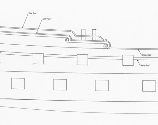
Hi Siggi, I am not sure of how the port lids were secured; I expect some of our experts will answer this soon. But in the meantime, could you post a picture of the framing of the upper deck at the stern, where the rudder head comes through? I am fascinated to see how this worked out. Best wishes, Mark
-
Hi Ed, Thanks for the very interesting comparisons. It does get one thinking: the Royal Navy tradition of a web of large (beam), medium (carling) and small (ledge) structural members is not the only way to frame a deck required to carry a heavy, fairly uniform load. Indeed, a system like the Young America with large (beam) alternating with almost-large (long ledges) might even make more sense. I had understood the Royal Navy idea was to get the large beams directly under the guns, but at least in the case of the Bellona, this was not uniformly accomplished. A series of large and medium beams like in the Young America could have been more effective structurally. Also of interest is whether one of these compared to the other uses more timber, or requires more labor intensive cutting of joints, etc. And, perhaps the increasing scarcity of timber in England encouraged using up the smaller pieces in the many ledges. If I could remember any of the structural engineering I learning many, many years ago in architecture, I would do some calculations to see just how efficient each of these systems really are in comparison to each other; but I don't remember with any confidence, and it will have to remain an interesting speculation. And after all, we have no way of letting the 18th century shipwrights know that there could have been a more efficient system for framing their ships! Best wishes, Mark
-
Hi Siggi, Great to see you started a build log. You have an exceptionally nice project, well worth sharing. That is beautiful carving and painting, nicely executed! And, I can learn a lot from you since the Dragon is the sister ship to the Bellona. Mark
-
I had put in an advance order on Amazon for this book advertised to come out this October. I just received notice from Amazon that it is no longer available, and they cancelled my order. Does anyone know what happened to this book, and is it available anywhere? Mark
-
Confederate Submersible H. L. Hunley
SJSoane replied to AndyHall's topic in CAD and 3D Modelling/Drafting Plans with Software
Very nice drawings. Adding the sailors really show off the scale of the hull. I think that sub design is the ultimate in a nightmare for people tending towards claustrophobia! Best wishes, Mark- 7 replies
-
- 1
-

-
- Hunley
- H. L. Hunley
- (and 5 more)
-
Ben, I just looked in. Very nice work! Mark
-
Beautiful oven, Gaetan. So the brick was laid up within a wooden box? Very interesting detail. Mark
-
Hi Ed, I just noticed the pattern of framing a deck here is different from the Naiad and other 18th C ships of war, in that there are fewer banks of carlings transversally, and therefore longer ledges. And there appears to be only one ledge between beams. I assume this is all because the clipper carried no heavy ordnance, and is narrower? how do the Young America and the Naiad compare in length and width? Best wishes, Mark
-
Hi Remco, I am just catching up after a long absence. The draught marks are terrific, both stem and stern. You have an exceptional hand with a chisel. Mark
-
Hi everyone, I have been away, and just got back to the website. Greg, Michael, druxey and Ed, I hoped I wouldn't actually have to build it, once I drew it....;-) All kidding aside, it is interesting how precise one has to be with CAD, or it doesn't get drawn at all. When I first drew it freehand in my original hand drafted drawings, I now realize I was able to fudge exactly where things began and ended, and I am sure my curves were not sections of accurate circles. Freehand has its virtues. And yet, when it is actually built at my small scale of 1:64, the subtleties of where exactly the scroll begins hardly matter. It is a lesson in understanding appropriate tolerances at different scales. Wayne, I hope I didn't lead you down a rabbit-hole with this exercise. But it sounds like you learned as much as I did about interesting geometrical constructions from the 18th century and before (the volute in Classical architecture goes back to 500 BC or earlier). It is very satisfying to puzzle through a geometrical construction, and then when you draw for the final time, everything just falls into place. Obsession has its rewards! This construction is also a reminder for me that our predecessors relied much more on relative proportions and geometrical constructions for forming complex shapes including an entire ship design. We don't tend to think as much today of objects in terms of their proportional relations to other objects when designing and drawing. Perhaps we lost some important ways of looking at the world. And Ben, I am glad solving my puzzle helped solve yours regarding the dotted lines in the stem construction. Further evidence of why this website is so valuable to us all. Best wishes, Mark
-
Byrnes Thickness Sander for removing Cup?
SJSoane replied to Stefonroman's topic in Modeling tools and Workshop Equipment
Any thickness sander will do this, if the cupping is across the short width of the board, and you put the concave surface down. But is if it is badly twisted down its length, it will just thin the board and leave the twist. In this case, you need first to plane one surface flat. -
Michael, I somehow missed that you were back working on this again, and you continue to astound. I love the framing jig, the plan to build a working engine... amazing. I need to pay closer attention! Mark
-
Ed, I am just catching up with your build log. You continue to offer an invaluable manual for model ship construction with every post! Mark
- 3,618 replies
-
- 2
-
-
- young america
- clipper
- (and 1 more)
-
Alexandru, I have not been able to look in for a time. Now I am catching up, that is indeed a beautiful anchor. Perfect craftsmanship! Mark
-
Remco, it is looking very good indeed! And your clamps are terrific. did you do the knurling with a Shoreline knurling attachment? Mark
-
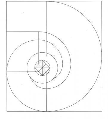
Hi everyone, I am slowly working up some CAD drawings of the Bellona, to consolidate all of the changes I made over the years to the original hand drafted drawings. I thought some of the more obsessive of us out there might enjoy seeing how I finally figured out the geometry of the scrolls or volutes at the fore edge of the quarterdeck. My architecture background came in handy, because I believe the geometry in the Bellona's volute is the same construction as that used to make an Ionic volute capital in Classical architecture. I hope the enlarged geometry is self explanatory, but just in case, a square on a 45 degree angle is inscribed within a circle. The mid points of each side of the square are projected out as shown. The compass point is first placed on upper end of the 6 o-clock line, and the pencil end goes down to the end of that line. A compass arc is then drawn to the 9 o'clock position, and the compass point is then placed in inner end of the 9 o'clock line. A compass arc is then drawn to the 12 o'clock position, and so on. You will notice that the square inscribed within the circle is not the same diameter as the final central circle that shows in the volute. It took me a long time to realize that these did not have to be the same size, and indeed cannot be if the scroll is to take its final shape. I had to experiment with how big the construction circle needed to be, to make the volute fit in its proscribed space. Finally, the circle at the fore edge of this construction does not have the same center as the volute; its center can be seen at the lower end of the vertical line which intersects the topmost line to the upper left, and the beginning of the outer circle. Many wasted--I mean happy--hours were spent figuring out where the centers are for all of these constructions, to match the appearance of the scrolls in the Admiralty drawings. At this point, is anyone wondering if I am procrastinating about starting working on the model itself again? Best wishes, Mark
-
Wood Lathe and Router table
SJSoane replied to michael mott's topic in Modeling tools and Workshop Equipment
Michael, I didn't know you were a watercolor painter. Your exceptional talents run deep, and I would see the unexpected gift as a reflection of good karma! Mark -
Beautiful details. It looks like photos of full size. Mark
- 662 replies
-
- 1
-
-
- bonhomme richard
- frigate
- (and 1 more)
-
I just picked up TurboCAD Deluxe for the Mac, and after an initial crash (before I learned not to type in the "-" between feet and inches; it thinks it is a subtraction operation), it has worked exceptionally well. Well laid out interface, responds well to drafting with bezier curves, etc. I would recommend it, at least for a Mac. I don't know about the Windows version. Mark
-
Beautiful work, Danny, and I particularly like the fids and topmast crosstrees since I haven't seen these modeled so well. Mark

