flyer
-
Posts
1,004 -
Joined
-
Last visited
Content Type
Profiles
Forums
Gallery
Events
Posts posted by flyer
-
-
-
Hi Bob
But, that flag looks quite good. You could soak it with watered glue before folding to make the crinkles last.
A few years ago I built Caldercrafts Granado which, I believe, is almost identical to the Amati kit. Perhaps CC provides the better manuals and certainly the better guns.
The kit lets you build a great model with a lot of interesting details. There is also a book available in the Anatomy of the Ship series. Altogether Granado would be a very rewarding project and with the experience you have, you would be able to build a gem.
Cheers
Peter
-
Hi Bob
As far as I can make out, the second pins from the front on both aftermost pin rails are free for the flag line.
Or: Sometimes, when I run out of belaying points I use the same point to belay two different lines. I'm not sure about the real ships, but if you consider all those additional lines necessary for the sails (including buntlines, reef lines etc.) I guess they run sometimes out of belaying points too.
If you don't like the flag coming with the kit, you could hand paint one on thin cotton and even choose the squadron you want to attach your Vanguard to. At the battle of the Nile Nelson was a rear admiral of the blue and she probably showed a blue ensign (as did the Titanic btw. either because Cpt Smith was a honorary CMD in the RNR or she was a Royal Naval Reserved Merchant Cruiser).
Cheers
Peter
-
"... then have figure out what to do with the damn thing."
Hi Bob
In real live usually the admiralty decides where the ships have to go...
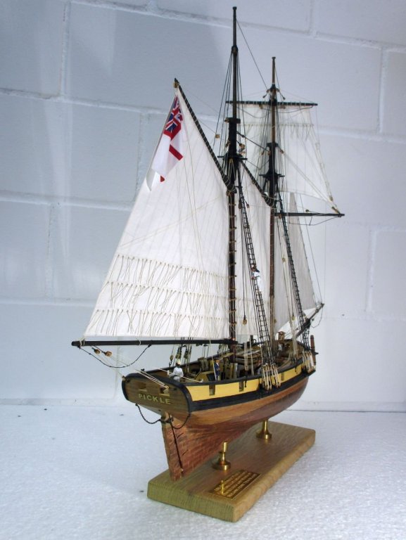
Ensign halyard: Usually a single block (suggest 3mm) is mounted at the end on the main gaff. A flag line (0.1mm natural thread) passes through the block with both ends running. Both ends are belayed at the same cleat on the inner bulwark (or a similar belaying point) just about abeam of the block.
That means that you belay the line on the cleat, the opposite end leads up through the block and back down to be belayed at the same cleat. The ensign is fixed to one of the ends.
Similar cleats should be provided on both sides, port and starboard, to enable the ensign to be set on either side of the gaff sail.
This description follows the manual of Caldercrafts 'Pickle'. I find CC's manuals usually very well researched and accurate.
Below you find a picture of my Pickles Ensign and its halyard.
Cheers
Peter
- KingDavid, mort stoll and glennreader
-
 3
3
-
Hi Bob
Thank you very much. I will follow the manual then, and paint the inside of the gallery a light grey as on victory and the 'floor' dark grey to black.
You just saved me a lot of unnecessary, fiddly work.
Thanks
")
Peter
-
Hi Bob
Thank you for the prompt answer. We are talking nearly about the same, only I was thinking of the inside of the side galleries. In the draft below You see the sections within the red marked areas on parts 58 (upper) resp. 60 (lower) which I would take out in order to create a side gallery which also has some depth below the windows. The question is now if you think you would see a difference -looked on from the outside of the finished stern- to your version where the 'floor' of the side gallery lies directly below the windows.
Instead of nibbling those two closed triangles into frames with a high risk of braking them during or after the process, I think the surface could also just be painted black to suggest some depth.
What do you think?
Thanks
Peter
-
Hi Bob
You are making great progress on your wonderful build. To successfully correct a little mistake now and then is part of the fun - or so, I've been told...
Watching your Vanguard coming to live is always a motivation boost for my Bellerophon build.
A question, if I may:
I'm actually pondering about those triangular side gallery patterns. I had the idea to work those two, on each side, directly below the windows into frames instead of the closed triangle. That way I hoped to create an impression of an real side gallery with some depth. The whole construction would however lose some stability and it would be fidgety work. Do you think the difference between your way of building, according the manual, and a side gallery with some depth below the windows would be noticeable at all from the outside?
Happy modelling
Peter
-
-
Hallo Nils
You are a true artist.
Congratulations to finishing a great project.
Peter
- Omega1234, Mirabell61, Martin W and 2 others
-
5
-
Hi Martin
After soaking them in water for 1hour it went quite well. The correct placing of the gun ports in regard of decks and frames is a bit tricky and if I really was successful will show only when trying to place the gun port frames and the guns. However the necessary bending in two directions of the stripes produced some of those mentioned bumps and dents (visible in the third picture where the plywood joins the planked part).
Thank you, Mike
Hi Jason
Yes, 1/64 would be great but huuge! And 1/72 is almost the same - just imagine the original ship being only a bit farther away from you.
Thanks for the information about the rail. So the Trafalgar configuration was probably as per kit. However as there is no definite information I will take the liberty to build as the plan in the book or those from Bellona show and pretend that the bulkheads were never heightened.
Cheers
Peter
- mtaylor, Martin W and Bill Morrison
-
3
-
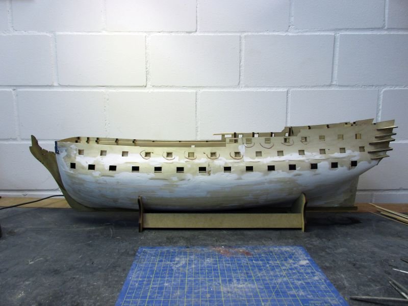
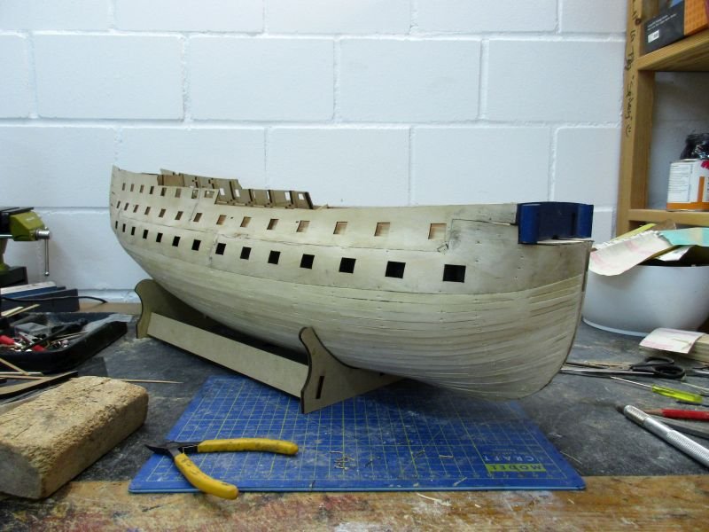
Despite some distractions the first planking is now finished.
Some dents and humps are showing and sanding, filling and sanding again will now start in earnest to get that hull shape which was intended by Sir Thomas Slade.
- egkb, Landlubber Mike, Jobbie and 11 others
-
14
-
Hi Mark and Mort
Didn't' spend enough time in the yard lately - I had to read that book. While there is just some additional information in regard of building the model, the story is catching, interesting and a great motivation for the build and very well written - a page turner.
Thanks again for the hint.
Cheers
Peter
- mtaylor and mort stoll
-
2
-
Hi Martin.
Especially the shot depicting a birds view shows how wonderfully those steps fit your Pegasus. Great work.
Cheers
Peter
-
Hi Bob
I'm unsure if you want to use the saddle for the gaff (upper piece of wood) or boom (lower...).
The gaffs yaws vertical movement was controlled by the 'Gaff Throat Halliard'. If you don't have information about that in your Petersson, I could help.
The saddle is used to support the booms yaws and was fixed to the mast.
Cheers
peter
-
Hi Bob
The question about that 28 in your post on top of this side intrigued me. After all I will have to answer it for myself when I will reach the same stage of the build (in 10 years or so).
Again I looked for an answer in Lees' book. It seems that 28 refers also to the small inset in the plan marked 'Mizzen boom tackle detail' and shows in fact the boom sheet. Lees writes about that:
'...A double block was sized into a strap around the boom inside the taffrail; another double block was strapped to an eyebolt in the transom. The standing part of the sheet was made fast to the strap of the lower block and the hauling part belayed to a cleat in the deck.'
That cleat would be your 28. And obviously the 'eyebolt in the transom' is missing in the plan and could be in line with the other eyebolts behind position 28.
For the rigging of your next project I highly recommend that book The masting and riggging of English ships of war 1625 - 1860 by James Lees. It's a tremendous help with questions about rigging and also helps to correct mistakes sometimes even in building manuals as good as those from Caldercraft.
Cheers
Peter
-
Hi Mark and Mort
Thanks for the hint about that book.
Couldn't order it via amazon.com in the US but could order it via amazon.de (shipped from the US!) for double price! Wondering what kind of strange politics are at play here. Well, we should keep politics off this forum but perhaps I'm nevertheless allowed say that the louder the politicians yell, the more I detest them.
In politics stupidity is not a handicap. Napoleon Bonaparte
Cheers
peter
- mort stoll, Martin W, Bill Morrison and 2 others
-
5
-
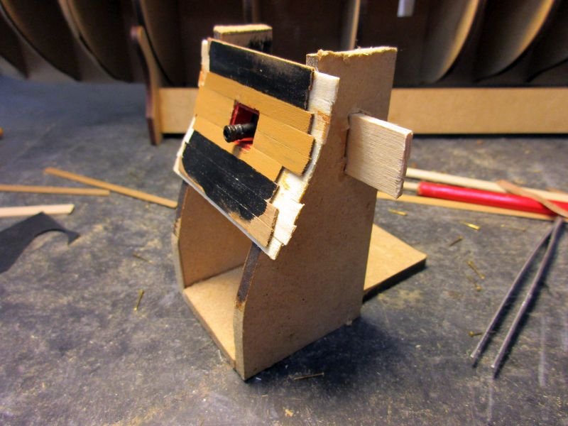
test bed for dummies
Two leftover parts from the 5mm sheet with the frames were put together to simulate the profile of the ships side; a strip similar to the strips holding the dummy guns was installed and the whole thing roughly planked.
A first trial dummy carriage was put together from three simple parts and painted red.
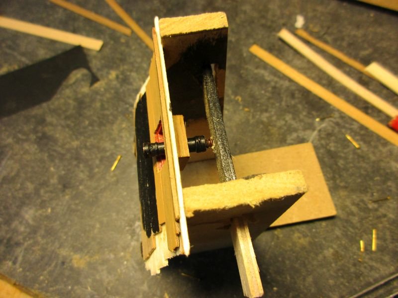
The installation on the test bed went easily and the overall impression is quite acceptable and an definite improvement. The really tricky part was the installation of the (very rough) gun port frame in 4 separate pieces which showed that even a limited access to the inner sides was desirable. However after already having broken off two upper pieces of the frames I put in both inner walls on the lower gun deck before going on. This should add some stability and I will leave off the lower gun deck for the time being.
the test bed
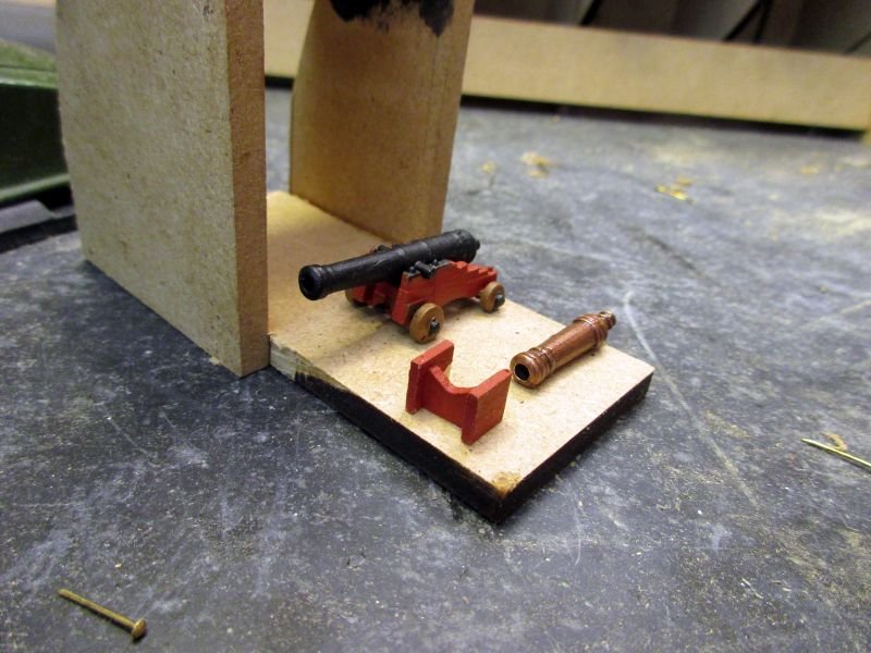
Slightly reworked gun carriage for the upper gun deck and dummy carriage for the lower
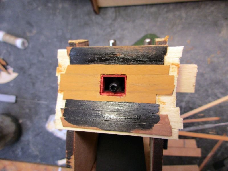
gun port with dummy carriage added in the second picture

- Jobbie, hamilton, Bill Morrison and 9 others
-
12
-
-
Hi Tony
Thank you. Regarding the victory plans, I don't know for sure which of the 3 ships they are representing but as the basic variant is Vanguard it should be her. Some differences among the sister ships might show up during about 30 years after being built.
There is an oil painting in the NMM in Greenwich with the title 'Scene in Plymouth Sound in August 1815' (BHC3227) which was painted in 1816 and should be a quite reliable source. Unfortunately the small reproductions in the web don't show the exact details of the disputed area.
Your Bellerophon is a gem and I hope you will post more pictures.
Cheers
Peter
- Jobbie, mtaylor, Bill Morrison and 2 others
-
5
-
-
Hi Alan
Thanks for your input. I presume those plans in the NMM depict the situation as built. Any idea about the configuration at Trafalgar? I guess, I will have to decide quite soon depicting what time and in which configuration / colour scheme I want to build her.
I have noticed your scratch built Billy Ruffian before and admire you for that enormous task you took in hand. Being lazy, I'm glad to have a kit to tinker with.
Cheers
Peter
- Martin W, Bill Morrison and mtaylor
-
3
-
Awe-inspiring, beautiful work, Nils. And you did it in just 26 months and all from scratch - a masterpiece!

Keep up the good work.
Peter
- Mirabell61, Martin W, PeteB and 1 other
-
4
-
The kit has arrived - all 13kg of it!
The first look at the parts was promising. From different logs here I knew about what to expect and I wasn't disappointed.
However a few minor points seem a bit debatable:
The stern decoration was unfortunately just for my version made as white metal casting instead of the nice, a bit flexible plastic parts for the other variants.
Some additional adjustment work will be needed here.
As mentioned in another log the guns, carriages and especially the carronade carriages may need a replacement or a rework to be up to the standard of e.g. Caldercraft gun kits. It's a pity, that a kit of this quality offers those very nicely made but also very strange parts.
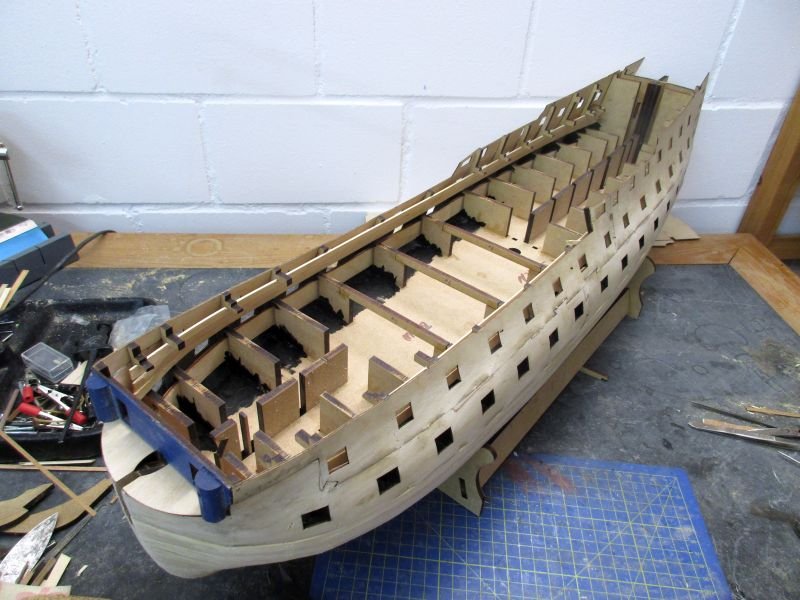
The skeleton
Fitting keel and frames together went quite smoothly. While putting in the plywood strips which are the base for the dummy guns on the lower gun deck I decided to try to leave the upper gun deck open while putting on first and second planking. The idea is to have access to the inside of the hull to facilitate the installation of some dummy carriages for the dummy guns. After installing the first inner bulwark on the lower gun deck however I found that they constrict access to the dummy guns altogether due to the tumblehome of the hull. To find out how to install and what kind of dummy carriages I decided to build a simple test bed for dummies.
impressive size...
access to the lower gun ports from the inside is almost blocked
-
Build log HMS Bellerophon
Introduction
A model of a ship of the line from the Napoleonic wars was something I wanted to build for a long time. From the range of kits available I ended up with 2 favourites. The selection of those two was because of kit quality (should be good), scale and size of the finished model. As my last 4 projects were all in 1/64 I tended towards the same scale.
Finally I had to choose between Caldercrafts Agamemnon (64) and Victory models Vanguard (74).
The decision for Vanguard was made because of the following points:
- the 74 is the classical ship of the line
-I can build the Bellerophon variant which I like for her direct connection with Napoleon (Here, in Switzerland, he had a much bigger influence (not all negative) than Nelson).
- copper plates are of better quality
- the scale is with 1/72 close enough to my favoured one and...
- the overall size is 10% less.
As additional information source I will use Brian Laverys book 'The 74-gun ship Bellona' from the Anatomy of the Ship series.
After checking the available build logs and comparing them with the Bellona plans as well as with the Bellerophon plan in 'The Ships of Trafalgar' I think that I will check and perhaps alter a few points:
- The bulwark of the quarter deck must probably be lower in its forward part to be similar to Bellerophon plans in the internet or to Bellona's profile. I will have to find out if the heightened bulwark was an later alteration and if it was in place in 1805. However in the book 'The ships of Trafalgar' is a plan for the Bellerophon which shows the lower bulwark variant.
plan from the kit...
.thumb.jpg.f5dd63fca70add6f8108c9fa35880549.jpg)
...and from the one available from NMM (on my wish list)
.jpg.1055f404192a3d063d853d1e24f5d34a.jpg)
The rail on top of the foremost gun ports is here interrupted. On other plans it is running through in one piece. As Bellerophone's skipper I will install a continuous rail (looks smarter).
- The kit's gun carriages are very nicely cast and show a lot of details - but look different from all the examples available in books or the internet. I have no idea where they found a prototype like that. Replacing them would be a lot of work and money. I will try to rework them a bit.
- The dummy guns on the lower deck are not quite satisfactory. Possible solutions would be replacements by full guns (again expensive and requiring a lot of work for an mediocre improvement) or the installation of 'dummy carriages' similar to those used by Michael (md1400cs) on his fantastic Vasa.
- The stern should gain a bit more transparency. I could make lighter side galleries and leave a door to them open. I guess to change the whole stern construction to enlarge the visible part of cabin and wardroom would be too much work for a small and hardly visible gain. However the taffrail overhanging the skippers balcony seems to low - overshadowing the cabin windows. The Bellona model looks a bit different. I will try to cut back that overhang a bit.
- The question if any, how and what sails will be bent on will be decided when starting on the masts.
- I haven't decided yet if the colour scheme will be pre- or post-1800. The Nelson scheme has a dark elegance but hides the wood...

.jpg.e49ca03a80db3d90af9803badf66f67b.jpg)
HMS Bellerophon by flyer - FINISHED - Amati/Victory Models - scale 1:72
in - Kit build logs for subjects built from 1751 - 1800
Posted
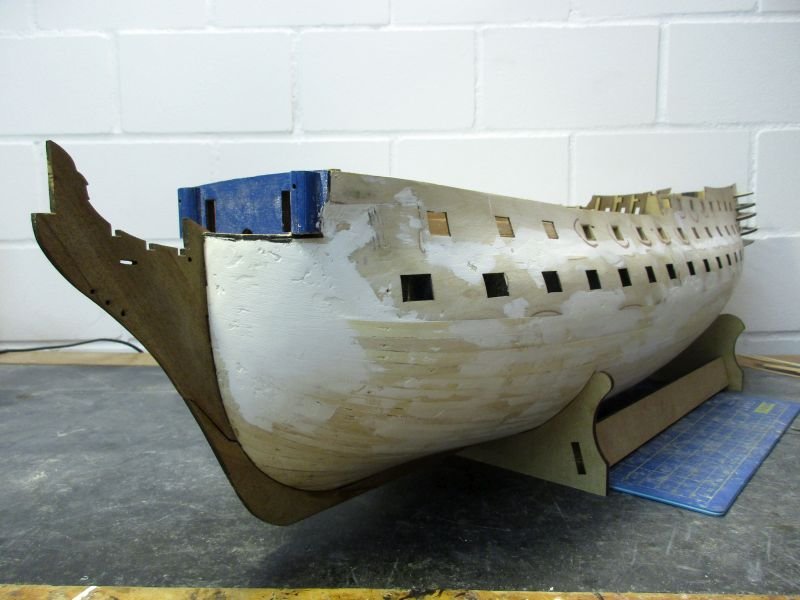
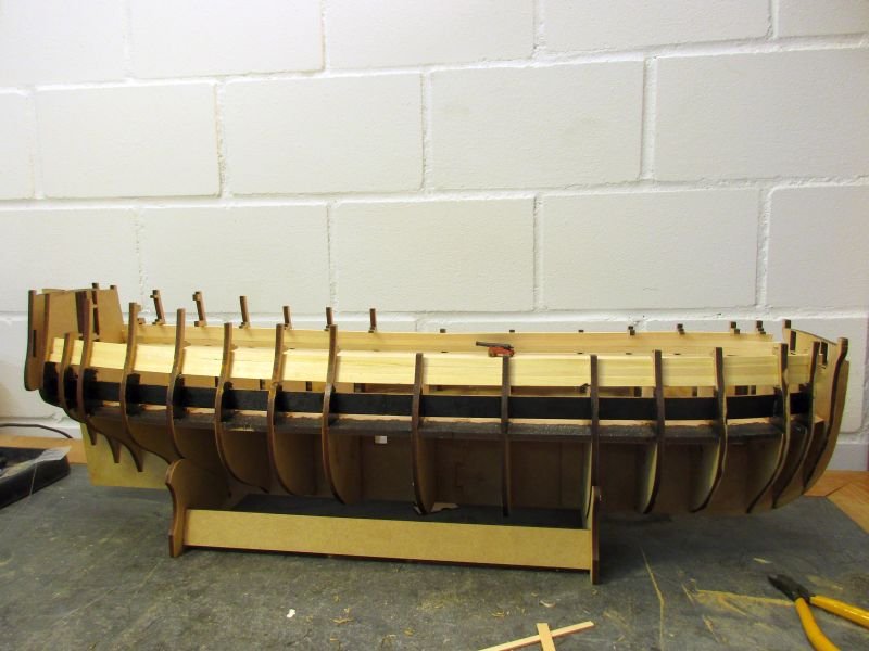
Preparations for the second planking
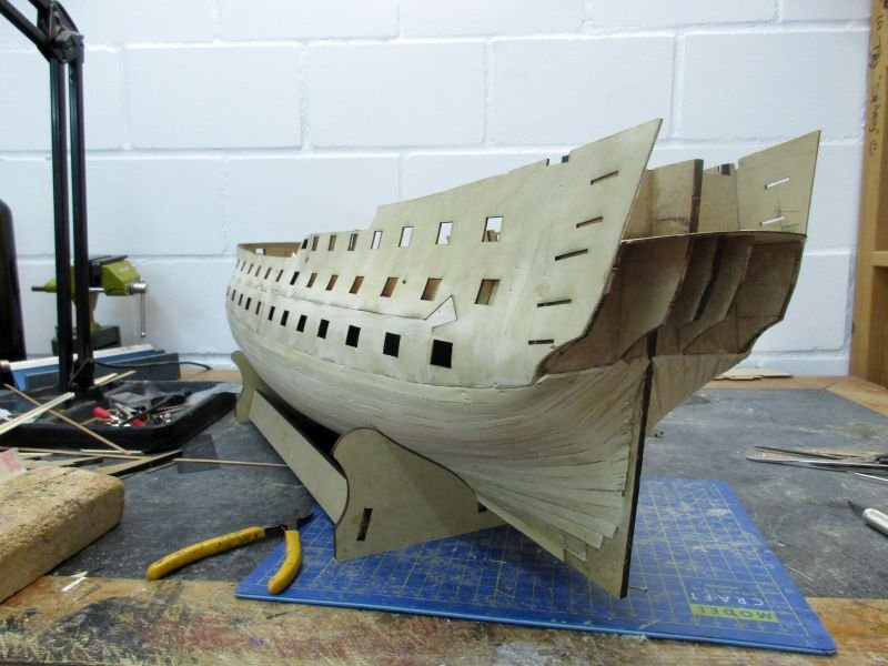
The raw hull was now treated repeatedly with filler and sanding to create smooth lines. To check those lines I relied on the plans of Bellona with cross references to Victory using plans from the two books of the 'Anatomy of the ship' - series.
The platform in front of the beak head bulkhead was planked.
The plywood piece intended to cover the lower counter broke in two while I tried to fit it into the required concave form - despite the previous soaking in water. I then rebuilt the counter with some leftover planks and covered it with a second planking, leaving space for the two missing stern ports. Those were placed according to the Bellona plans.
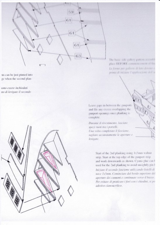
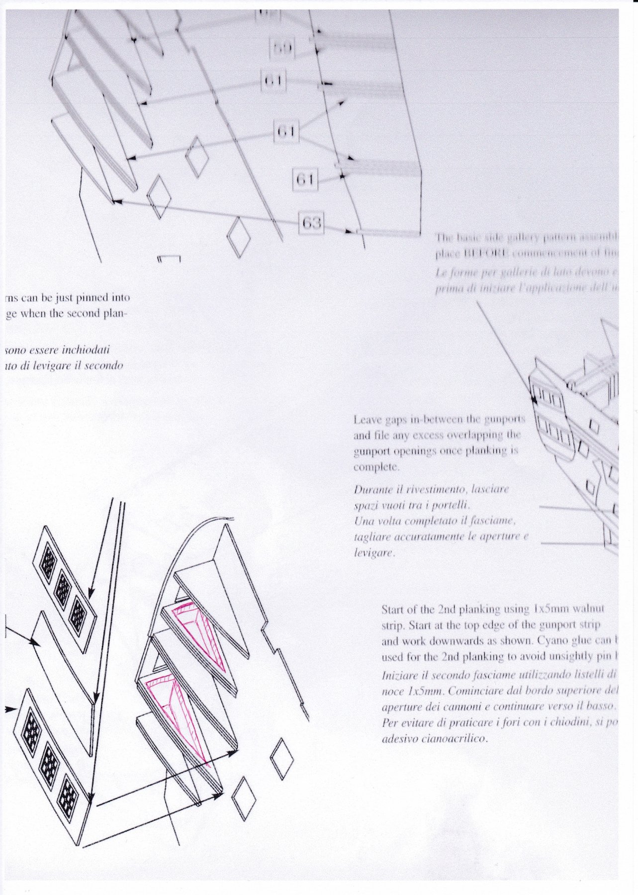
While building the skeleton for the side galleries I made some alterations. First I decided to plank the hull fully and thus set the side galleries onto the second planking contrary to the manual. This follows the method used on the prototype and will need some adjustments of the side gallery parts.
Those two side gallery frames which are directly below the windows were hollowed out into open frames in order to (hopefully) give some additional depth to the side galleries (and some space for the officers using them). I also doubled up the rips which will later determine the form of the gallery windows of the officers wardroom. The kits lower gallery is almost flat and I try to get a more convex form as seen on the Bellona. Similar adjustments will be necessary for the poop deck to form the upper part of the transom. Some problems will arise with the decorations, for the Bellerophon as they are made as three white metal pieces, which I will have to bend somehow...
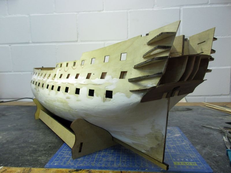
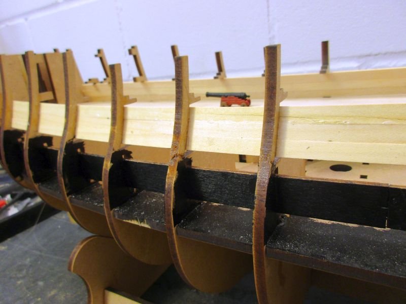
All the gun ports without lids were framed because the second planking will run over the frames, finishing flush with the openings. Some of those frames were made up to three times because trials showed not enough headroom for the guns when placing the frames perpendicular to the planking. The frames were cut to give horizontal upper and lower sills.
Finally the keel and the stem where glued in place, leaving the sternpost off. It will be added after sanding the second planking.
first deck planking
lower counter first planking with marked stern ports
second planking on lower counter - altered side gallery frames also visible as well as the 3 lengthened rips which will determine the convex form of the transom
rough gun port frames in place
The wood strip was a bit too small even when setting it onto the inside planking. As the opening will later be painted I can use some filler to cover the gaps.
her nice lines are starting to show