


flyer
-
Posts
1,004 -
Joined
-
Last visited
Content Type
Profiles
Forums
Gallery
Events
Posts posted by flyer
-
-
Hi Martin
This is a very special Fly you are building and will be an unique piece of art. Desultory work? Many of us hobby model builders seem to be a bit overcritical when judging our own work. But I say that you should not judge a finished model by every single little detail (which may sometimes leave a little room for improvement) but by the overall impression - which will be great in the case of your Fly.
(Of course I repeatedly say the piece with the overall impression to myself to overcome the frustration with my own botched details.)
Cheers
Peter
-
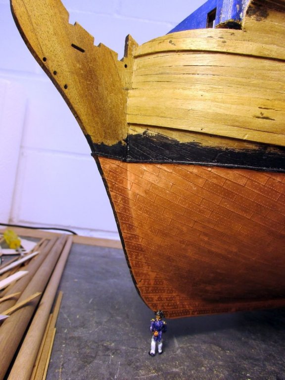
The coppering of both sides is now finished and the copper is being polished. I use Proxxon nylon-fleece brushes to clean and brass-wire wheel brushes to polish the copper. The untreated polished copper will accumulate a dark natural patina within a few years.
For breaks I'm coppering the lower half of the rudder. This itself was a bit reworked: The front edge was angled 30° to both sides to allow the rudder to turn and the back edge was sanded down to 3mm towards its lowest point.
Also the painting of the hull was started with the yellow strakes while I start wondering how I will ever get the puzzle of the quarter galleries together.
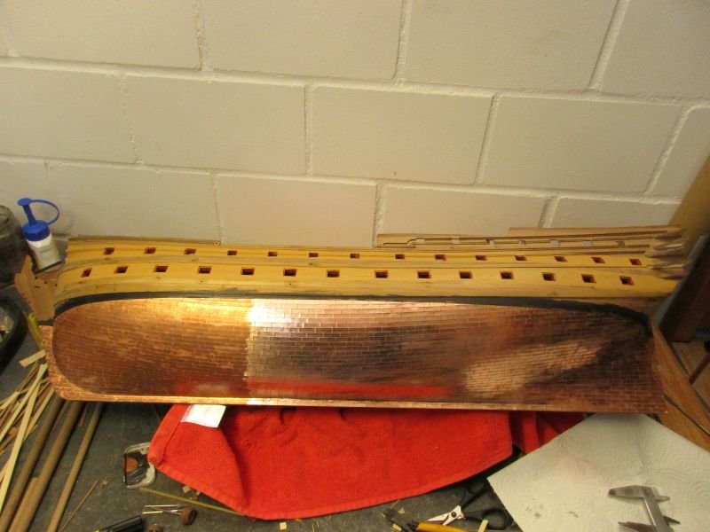
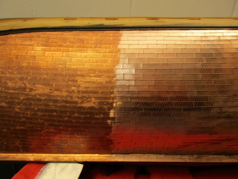
Copper partly cleaned on port side
Rudder being coppered
- Landlubber Mike, egkb, GrandpaPhil and 9 others
-
 12
12
-
Hi Bob
Very well done!
Perhaps you could treenail the end of the planks at the bulkhead because the planks would probably run up to but not under the bulkhead construction. This bulkhead seems to be a permanent one which needs not to be removed to create a continuous gun deck in action: there are no guns aft of it.
Cheers
Peter
-
Thanks to all for the compliments. It helps and encourages me to glue hundreds more of those little plates on. (About 3/4 done, only 600 to go!)
Still putting them on overlapping is a great help. Only those at the beginning and end of a line need to be trimmed.
Martin: Hour? I'm enjoying every second - being rather overjoyed by now.
Cheers
Peter
-
Hi Bob
Made exactly the same mistake. Finally I replaced the botched planks.
In Goodwin's book, on page 56, the bulkhead seems to stand directly on a beam while the planks end in front of it . However on page 54 the bulkhead seems to stand on the planks. On page 53 the model shows a vertical plank running across the bulkhead as lower edge of it and the deck planks ending at that plank.
3 different solutions within 4 pages: I think you have a certain liberty how to finish it.
Cheers
Peter
-
Hi Chris
First of all I wish you much fun and success with your newest enterprise and I'm looking forward to more outstanding kits.
Of the cutters I would prefer Alert and think it would make a good start for your new line of kits. Small enough for the beginners and possible to build alongside a bigger project (e.g. Bellerophon) for a change.
A smaller 28- or 32-gun frigate would fulfil a dream of mine. The ex-french La Tourterelle(28) or a Mermaid(32) would be nice or even an actually launched kit of the Surprise.
Do you plan to build in 1/64 scale or would a scale 1/72 frigate model perhaps sell as a nice complement to a ship of the line of the same scale?
Cheers
Peter
- mtaylor, Canute and hollowneck
-
3
-
Hi Michael
The cannon looks very good. I think you'r right about the position of the dolphins: They would help handling the barrel and therefore would best be placed above the centre of gravity. If the barrel stays more or less horizontal if you hang it by the dolphins it should be ok - otherwise you could try to move them. But in my opinion another point is more important. As far as I understand the trunnions are part of and cast with the barrel and should give the impression of being of the same metal as the barrel. Wood wouldn't be able to hold the heavy carriage to the fast recoiling barrel when firing the cannon.
You are on a fascinating journey with this build - thank you for taking us along.
Peter
- popeye the sailor and EJ_L
-
2
-
Hi Rob
Your Ethalion looks wonderful and I admire the way you build an unique model with this kit.
Having had the pleasure to build those ***** shot lockers for my Bellerophon I would like to share a few thoughts and hope you don't mind.
In my kit the supplied cannonballs were much too big and I had to replace them. In the case of your Ethalion the 18 pounder shots should have a diameter of about 5 inch or 2mm in scale - they look larger. Then I think you should try to settle those balls a bit deeper into the locker - now they are in danger of getting loose in just a bit of a sea and shots rolling across a deck could be mistaken as a first sign of an impending mutiny, as Jack Aubrey tells us.
My solution was to take 1mm wood strips, drill 1mm holes into it and then drill with a 2mm drill bit nearly through it. Taking the shots out now might be a bit of a fumbling but they will not accidentally drop out.
Cheers and keep up the great work
Peter
-
Hi Bob
You are making great progress with your Granado. It seems you finally got over your Vanguard withdrawal syndrome.
Only scratching just the outline of those lids ,I think, is out of the question in a quality build as yours. However the lid should sit flush in the counter and you will have to cut out the opening in the finished counter. I had the same problem but perhaps half an hour work with a sharp scalpel provided the desired result - although I had to rebuild at least one lid because it was suddenly too small...
Cheers
Peter
-
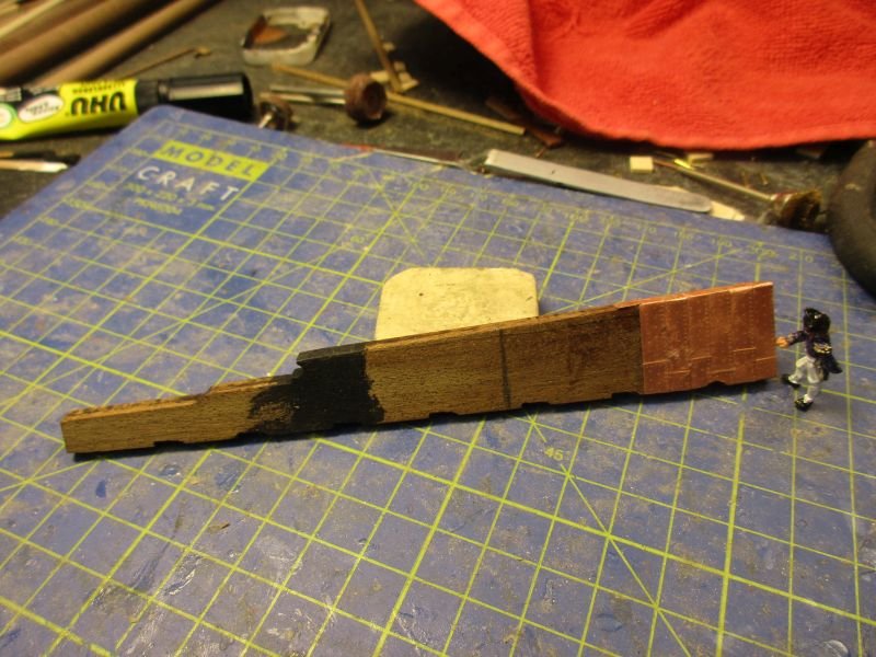
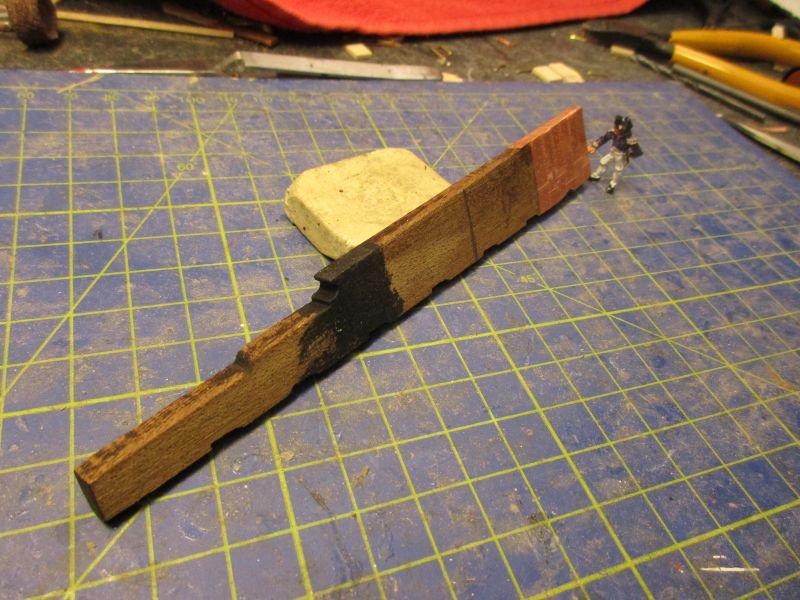
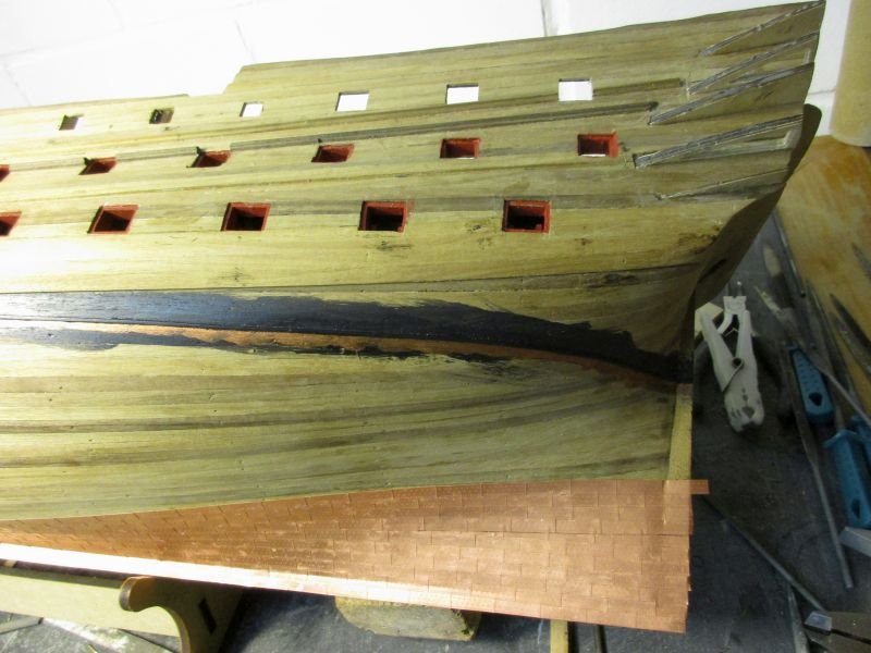
First (port) half of the coppering is done. Me, I'm looking forward to a nice diversified work, like knotting ratlines. The copper will be polished after both sides are done. The amount of copper plates was just sufficient. By careful use of trimmed leftovers I managed to keep enough full plates to cover rudder and keel.
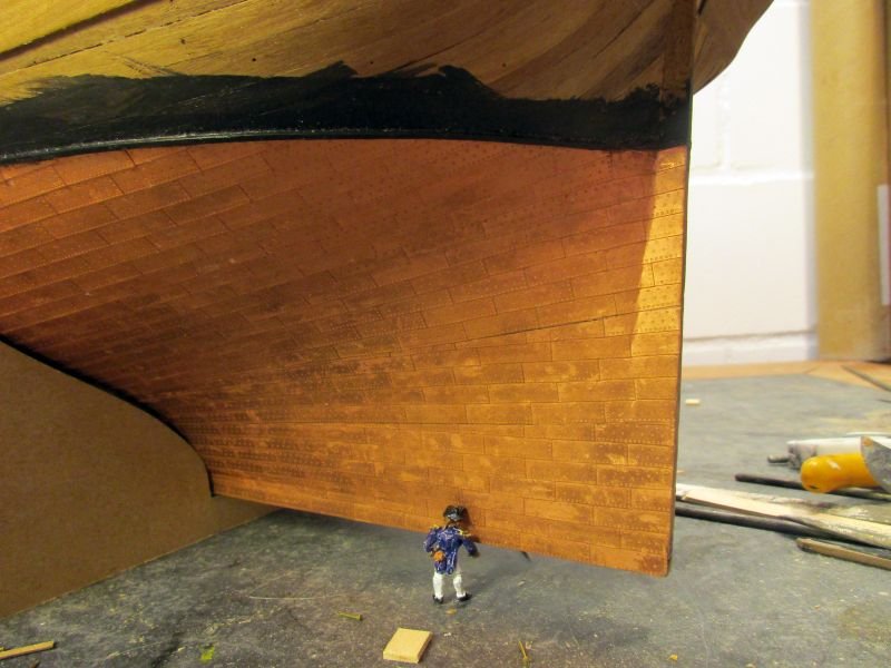
the scale figure of the captain shows just how much expensive copper was put on such a ship of the line
-
Hi B.E.
Looking great.
And that moulded strip is made ingeniously and looks good too. If there is nothing worse you have to 'live with' you are really living very well.
Cheers
Peter
- Martin W, Blue Ensign and Mirabell61
-
3
-
Hi Martin
You obviously don't believe in taking the easy way. Your Fly will be a unique gem.
Would there be a story behind that pile of hypothermic needles which you could tell over that beer?
Take care
Peter
-
Hi Dave
Thanks.
The linked article is a great one about a fact every modeller should be familiar with.
Adding 15% white seems be a bit much in scale 1/76 - but for the yellow colour on my Pickle build this could be about what I actualy took while the black there was right out of the can.
Generally I would and will add less white to black - a few drops up to perhaps 5% will make a big change already.
Cheers
Peter
-
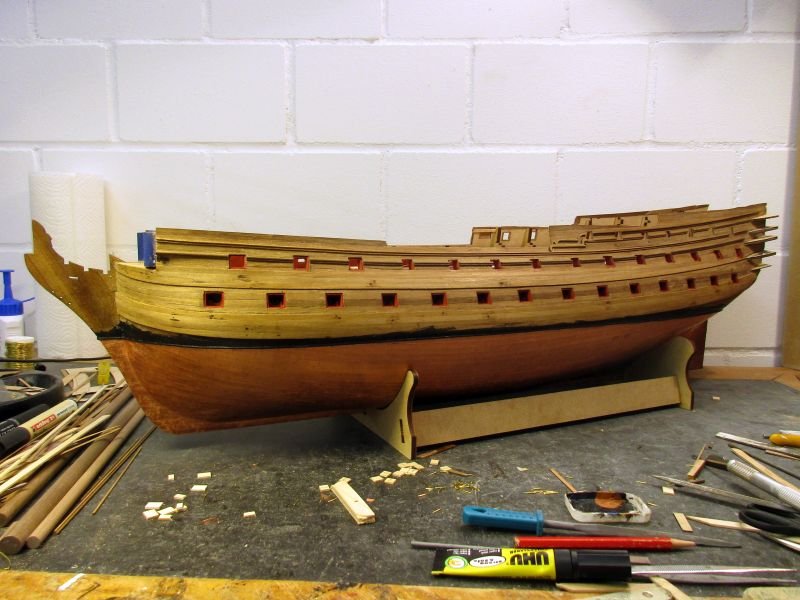
hull details, coppering
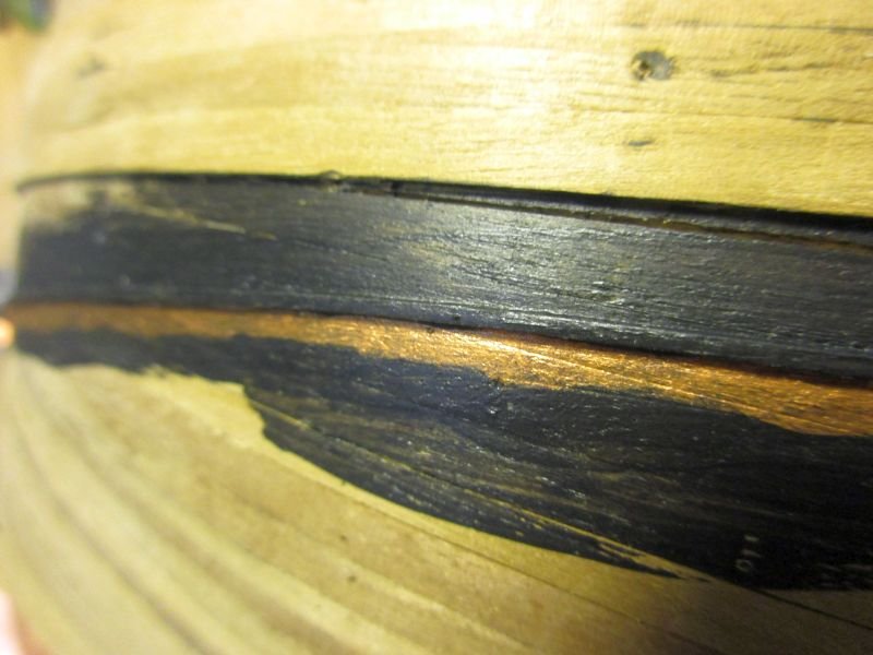
After installing some hull decoration strips I marked the waterline and put a1x1mm strip on it. It was then painted dull black. To give it a more realistic finish I mixed in some white.
(In a book, written by a professional model railroad landscape builder he explains about colour scale. By that he means that if you look at a model in scale 1/100 from a distance of 50cm it should look the same as the prototype from a distance of 50m. And from that distance colours look less bright because of the air absorbing some of the intensity. He says that's the reason that models tend to look like toys if you use original colours. He recommends to always mix in a bit of white or grey and to avoid shiny colours. I think it works.)
Below the waterline strip I painted a copper strip to cover eventual irregularities at the edge of the coppering.
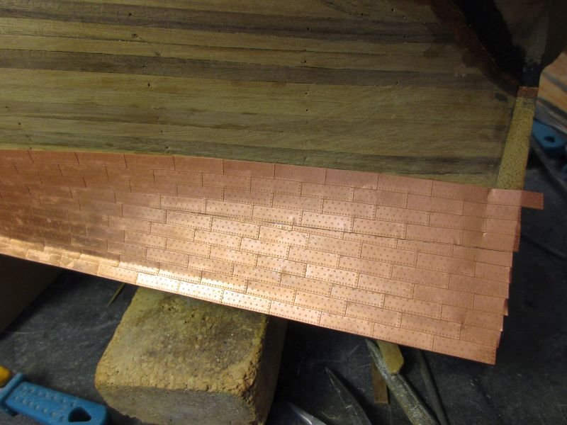
As on previous builds I broke of single copper plates and glued them on individually and overlapping, starting at the stern and the keel.
After putting on the first leaf of copper plates, I had the happy idea to check how many there are. 2400.
2400!
I just hope the skin on my fingertips will endure that as I have to peel off dried CA glue (and some skin) after each coppering session.
To have some variety I do small projects in between, such as adding outer hull details or more shot garlands - seems I can't stop making them, now I know how.
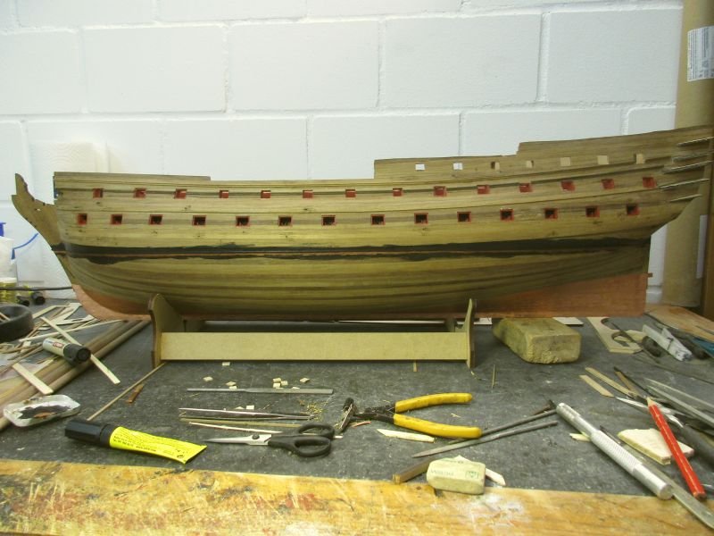
waterline marked and coppering started
waterline
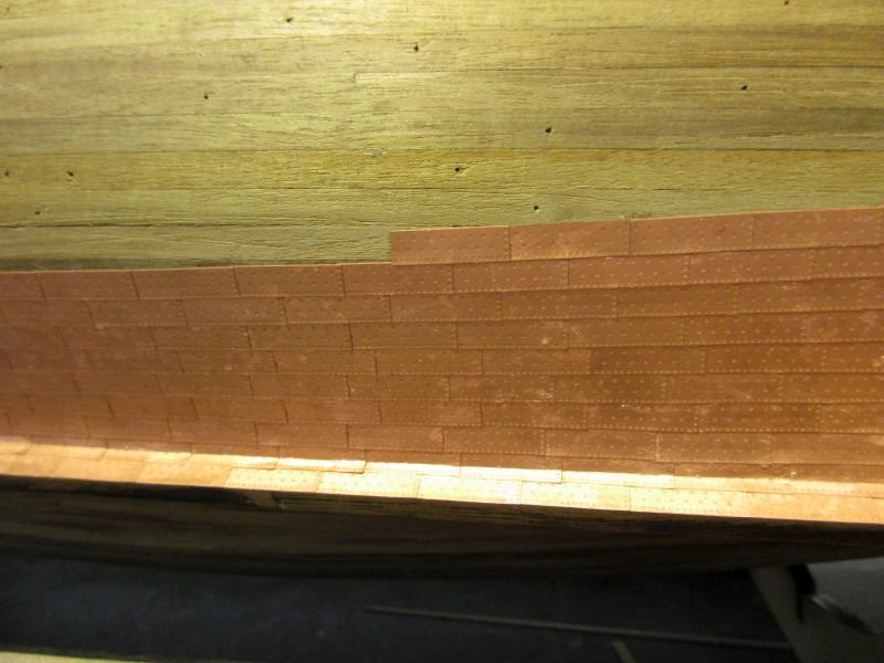
coppering details
additional shot garlands
- Martin W, mort stoll, OrLiN and 8 others
-
11
-
-
-
Hi B.E.
The planking looks good, especially in pictures 1295 - 1298, which show the most important viewpoints.
However, if I'm interpreting your assistants facial expression correctly he's only appraisal criterion is:
edible? yes/no
Good luck in convincing him to do the treenailing.😉
Cheers
Peter
-
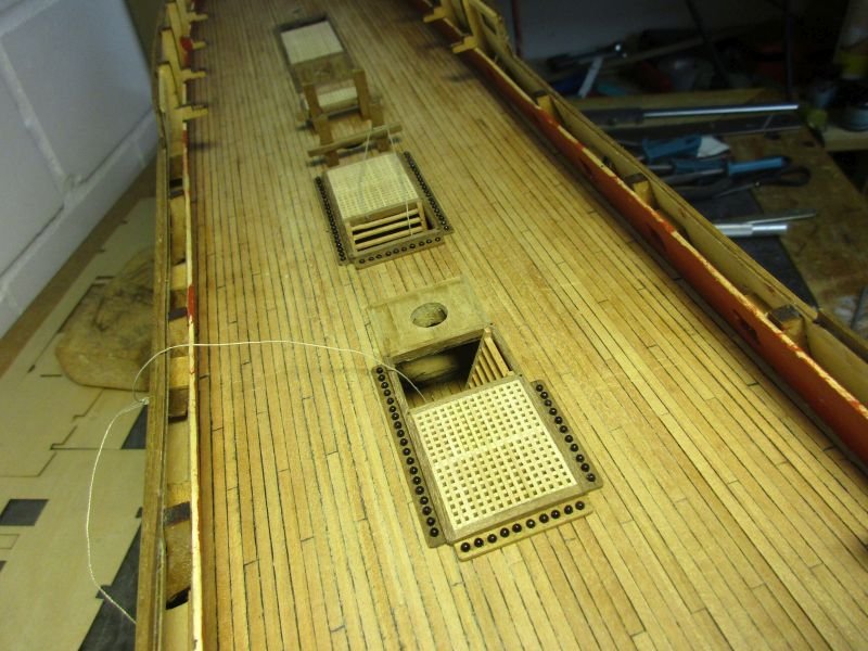
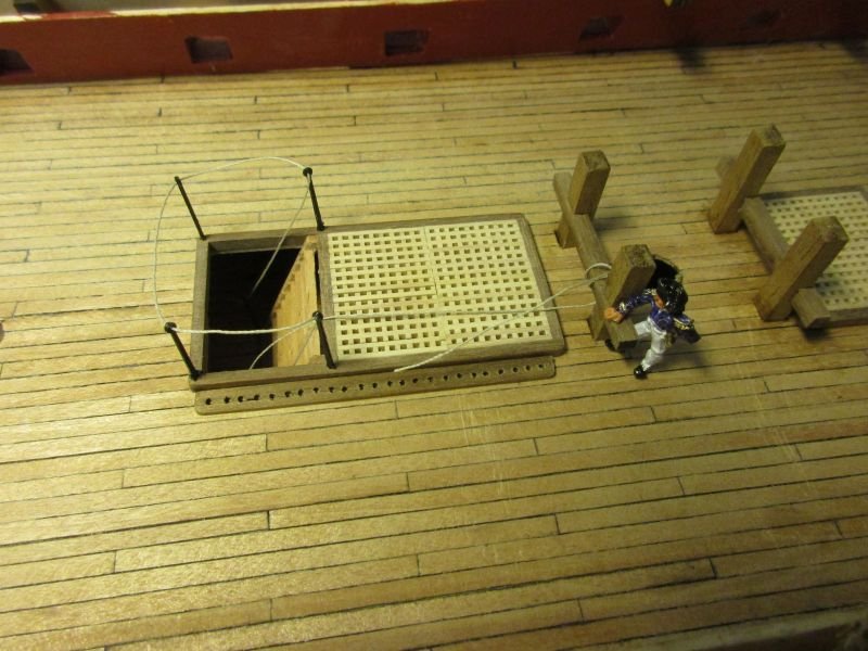
The equipment on the centre line of the upper deck is finished. The capstans are mounted on a 1mm pedestal framed with 2mm walnut. Finally I also managed to make shot garlands the way I wanted and filled them with 2mm balls. The part in front of the forward hatchway is left off to prevent the sailors stumbling over the shots.
The stanchions are leftovers from Pegasus and stand smaller than those from the kit but would fit below the capstan bars.
The oven will be placed directly on deck as any base below would be invisible after closing the deck.
The masts, stanchions and the oven are only provisionally put there and will be removed for the next step - detailing, painting and coppering the outer hull.
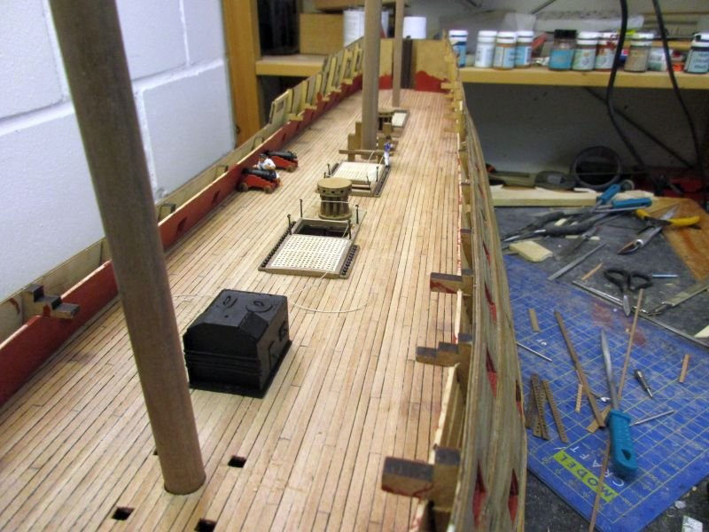
with only 2 guns in place the deck looks spacious
the captain wonders a bit about the carpenters many tries for the shot garlands
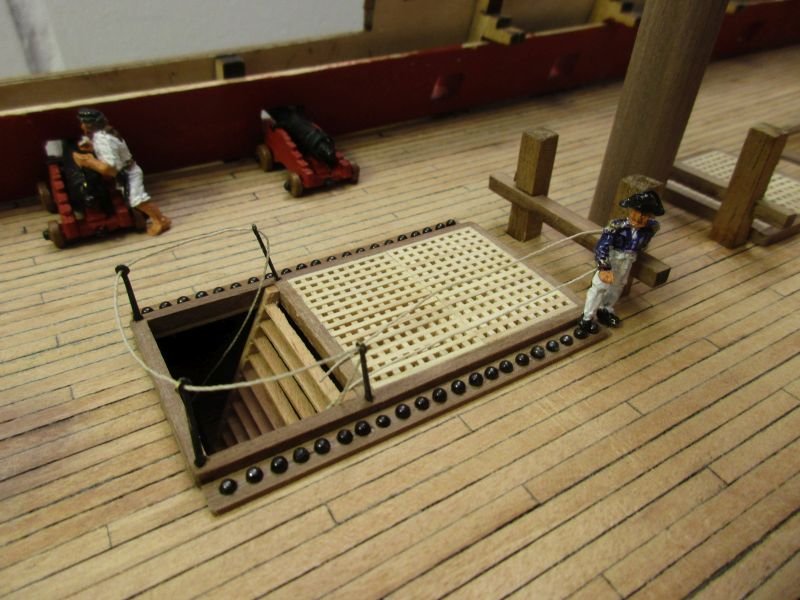
main hatchway
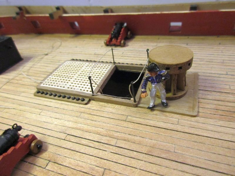
forward hatchway and capstan
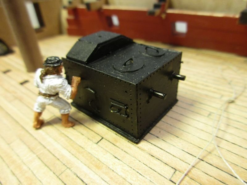
polishing the oven
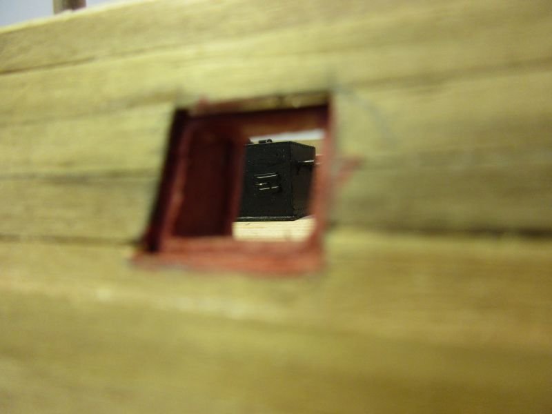
...and what will later be visible of it - but only after removing a gun
-
Presently I'm working on the 'furniture' of the upper deck. The oven is finished and set aside. It is a very nice detail - a pity it won't be visible on the finished model.
The hatches and ladder ways are nearly done. However first I had to plank parts of the gun deck through the hatches. This would better have been done before installing the upper deck but it worked somehow.
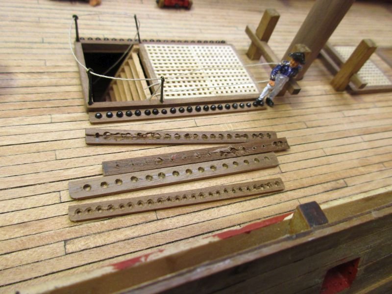
An unsolved problem are the shot garlands. Those furrows shown on the plans don't seem practical as the balls will roll and perhaps jump it when they're not full e.g. during an action in a lively sea. I try to fabricate boards with holes for the individual shots as seen on other models. This isn't easy. After splitting the first three attempts lengthwise I noticed that those cannon balls seem rather big. I found them to be 2,5 mm which is too big. For an scale 1/72 18pounder they should be less than 2mm. Fortunately I found some old 2 mm balls - a 30 years old leftover from the Vasa - which will be a better fit. So the next few tries will be with smaller holes.
I wonder also about the wooden rail around the forward hatchway, shown on the plan. It stands in the way of the forward capstan and differs from all the other rails. If I have enough parts it will replace it by stanchions and rope, similar to the others.
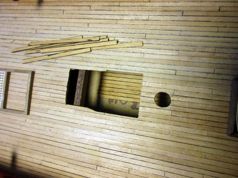
planking the gun deck - the hard way
the captain examines one of the attempted shot garlands and is not happy
(stanchions and rope are provisionally fixed and will be removed for gun rigging)
-
Hi B.E.
Your Cheerful comes along very nicely. There is much to say for building smaller ships as you can concentrate on every aspect and detail while when building a 74 you have to take some shortcuts or take an eternity to finish.
However, I'm a bit confused about the run of the planks. As I understand you are following Chuck's planking pattern which is based on an original plan. From some angles the run of your planks looks fine (pictures 332,336) while others give the impression of a distorted run (306,331).
Most planking tutorials emphasize that you should avoid bending planks sideways - something you definitely have to do. I got the impression that the small tape you used as battens did allow more lateral bending than a wood strip and therefore created a pattern with laterally bent planks. On the other hand the frontal view onto Cheerful's bow looks fine while on my models, where I usually start tapering with or just below the wales, I can keep a natural run on the planks but get a rather crowded bow planking and need quite a few drop planks.
I don't mean to criticize your work, I just wonder if you are happy with the way the planks are running - especially the one above the garboard? Do you think this is how it was done on the prototype and wood will eventually give up its tendency to warp?
Cheers
Peter
-
Hi Jacek
It is a lovely lady but she moves some quite some water - even in scale 1/72. I still have no idea where to place the finished model but as we have room in the house after some of the children left home the admiralty tolerates it.
To soften up your admiral (and even to improve your skills in the same time) you could first build a smaller vessel, such as Caldercraft's Pickle or the Lady Nelson from Victory Models. Those smaller builds look quite elegant especially if you manage to hoist sails. They don't take up much space and elegance should be appreciated by a Lady Admiral...
Cheers
Peter
-
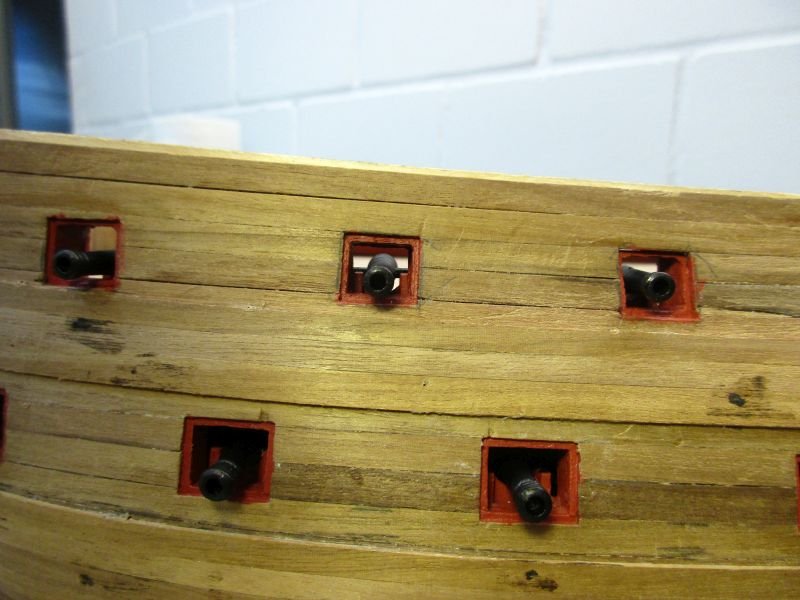
The gun carriages have now all been reworked. Those which will not be visible below the forecastle and quarter deck only got a reworking of their front part which will be visible through the gun ports. Also those barrels will not get the full details but will be used as cast. To paint them I finally found that a first coat with a simple big black marker works well as base for a thin second coat of Caldercraft's metal black paint. The markers paint seems to be aggressive enough to remove all traces of fat and is thin enough not to smear any details. Unfortunately it's to shiny to leave as finish.
Just for fun I provisionally put the guns on one side in place to have a look at the lady's teeth.
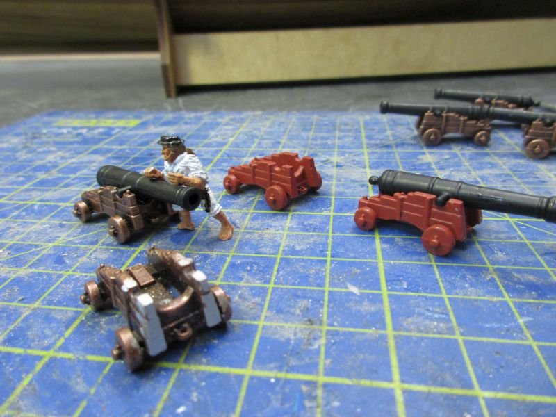
reworking of the 'hidden' gun carriages and barrels
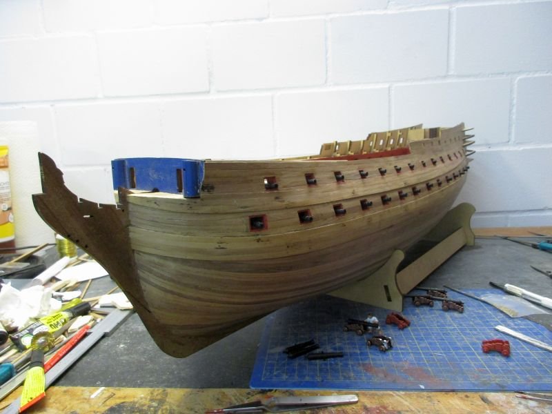
The lady's teeth are quite impressive
- Martin W, OrLiN and Landlubber Mike
-
3
-
-
Hi Rob
Your Granado is turning out very nice and you certainly made a brilliant recovery from your problems with the wood for the second planking. You even make me rethink my decision never to show treenails on my models. Although they usually show a bit more prominent than the scale would request they do add a feel of reality to a model.
Cheers
Peter

HMS Bellerophon by flyer - FINISHED - Amati/Victory Models - scale 1:72
in - Kit build logs for subjects built from 1751 - 1800
Posted
Building the side galleries was so far easier done than expected. I started with the 2 parts with windows - they were adjusted to the already installed end-to-end planking - and glued on. Then the adjacent windowless parts could be fit with only a small reworking necessary. The bottom 5mm mdf-part fit also quite well. However the top part of the side gallery needs a bit of rethinking and reworking. The kit asks to build something like a little pool on top of the gallery and this differs from any plans and pictures I could find. I suspect a misinterpretation of plans by the kit makers. I will install a more conventional, two stepped roof and hope to find room for the decorative parts.
Some details of the outer hull were also installed including the bolsters for the anchor flukes which are missing in the plans.
first side gallery parts attached
first four plywood parts attached
The roof is not finished, it needs one more step and the whole construction needs more filler.
hull details including steps
lower part of bolster