


EdT
-
Posts
2,209 -
Joined
-
Last visited
Content Type
Profiles
Forums
Gallery
Events
Posts posted by EdT
-
-
Thank you, everyone, for the comments and likes - much appreciated. Its taken some time to get through the work on the lower masts and tops. Many rigging questions needed to be studied and decided - one at every turn, it seems. Hopefully things should move faster.
Druxey, the outer parcelling at the masthead was easy to do and a small nod to authenticity. I have for a long time had a mental picture of the photo in Longridge showing this, and often regret not doing it on my Victory. As with many builders, I suspect, the image of the somewhat unsightly wrapping compared to the lovely, neat stack of served bights was a deciding factor. The mid-19th century docs I am using are quite clear about it. So there it is.
Sailor, I do not know the actual construction time for YA, but 6 to 9 months from laying the keel would be typical, with the unbelievable 60-day performance on John Bertram being the record (?).
Pat, I did not consider the material you describe for the case. Are there still photography stores?
cheers, everyone.
Ed
-
Young America - extreme clipper 1853
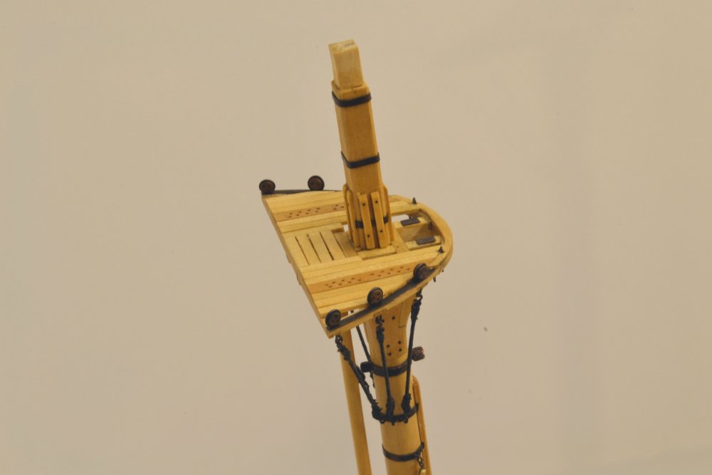
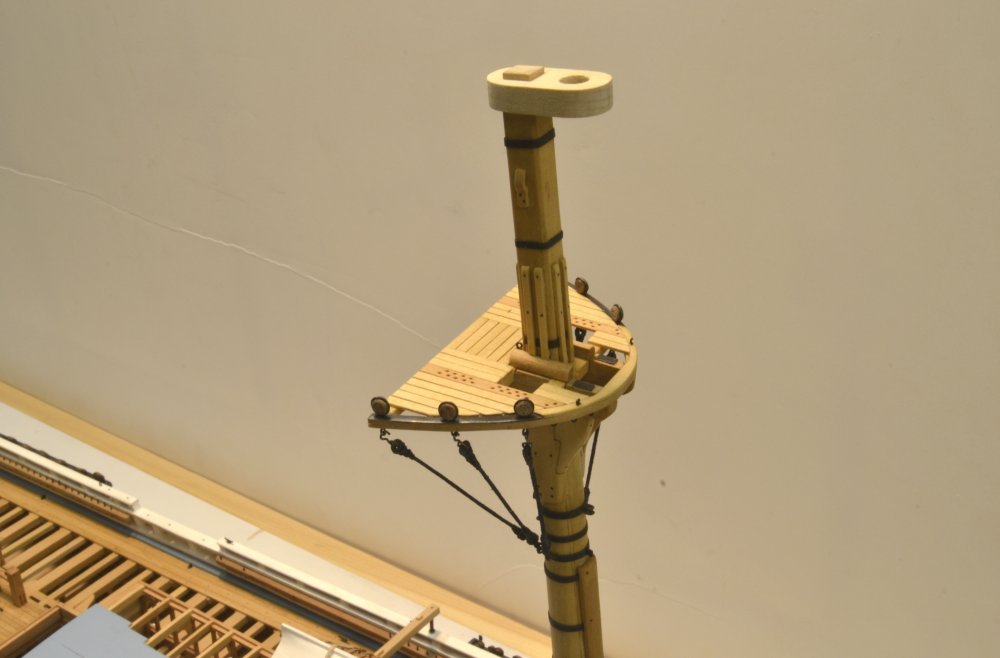
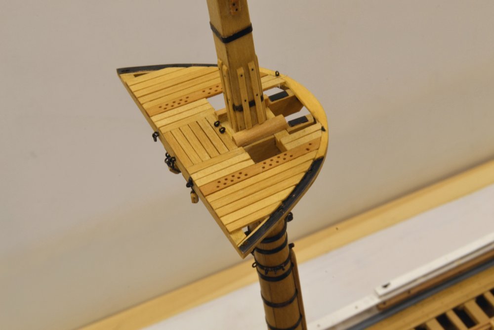
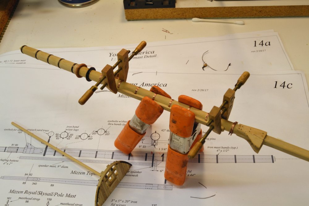
Part 204 – Tops and Futtock Shroud Wrap-upI am happy to be finished with the dust case and to resume the model work. The completion of the three mast assemblies with their pre-erection detailing, including their futtock shrouds, required just a bit more work and is now complete. The first two pictures show the mizzen top with its futtock shrouds installed.
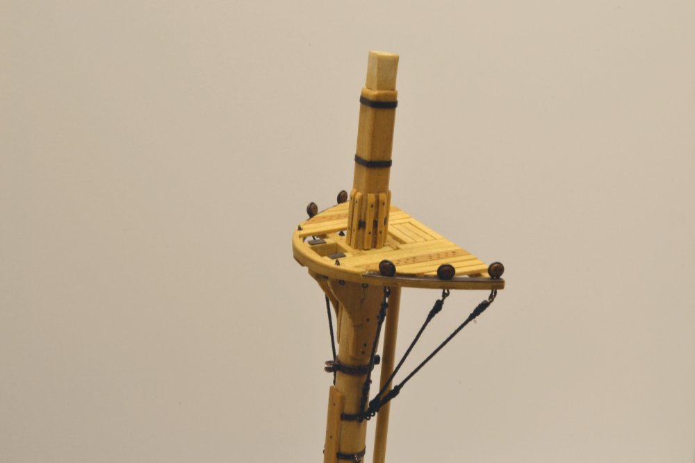
As mentioned earlier, these shrouds are served, fitted with brass thimbles at both ends, hooked to the deadeye straps at the top and secured to eyes on the mast band with lashings. The futtocks are 4 1/2" rope (5 ¼" on the main and fore), spun from three strands of linen thread, right-handed. The rope was dyed black with diluted India ink. Making these was described earlier in Part 196.
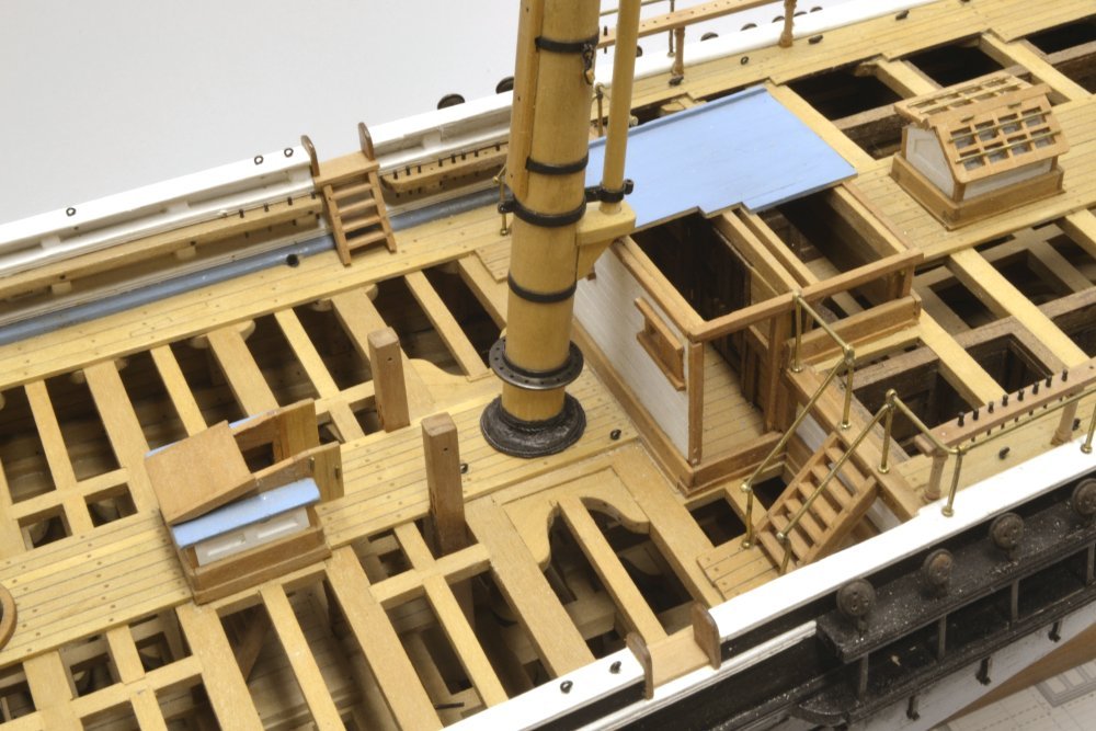
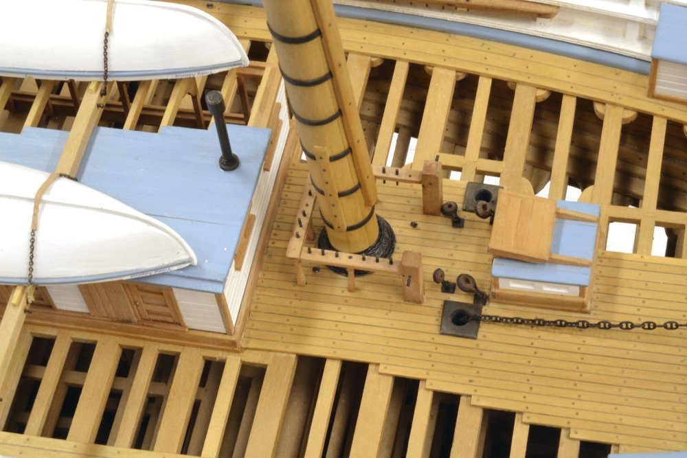
The last task on the lower mizzen mast was fitting of the mast coat at the base. This is shown in the next picture.
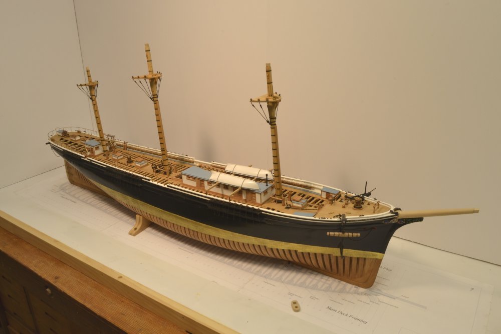
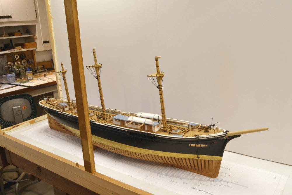
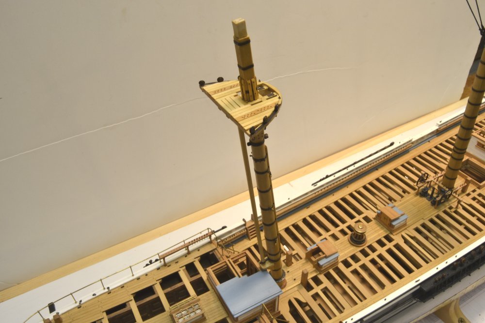
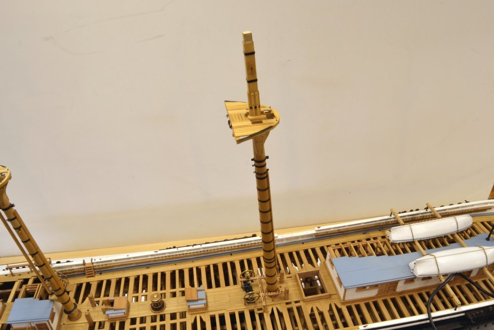
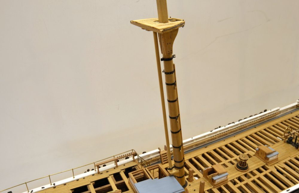
The next picture shows the model with the three completed lower masts fitted – still temporarily.
The next step will be to make the lower shrouds. The next picture shows numbers 1 and 2 on the fore mast, port side, looped temporarily over the mast head.
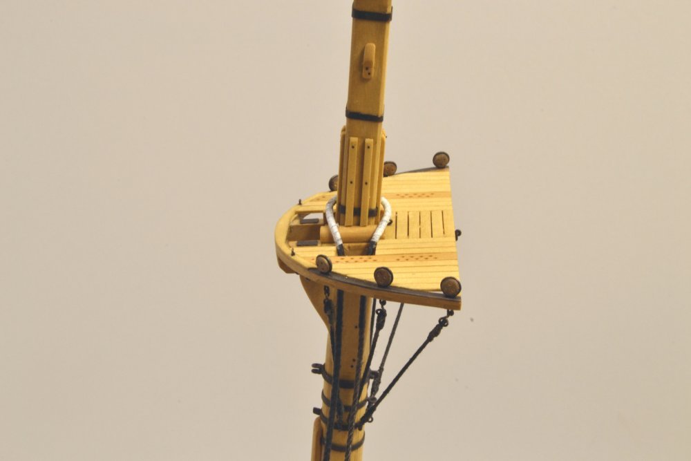
These two will actually go over the corresponding starboard pair. In each case the #1 shroud is served over its full length. The serving on #2 extends down to the futtocks as it will do on all the other shrouds. Parcelling has been wrapped over the serving around the mast head down to the top of the seizing, but has not yet been "tarred." More on all this in the next post.
Ed
-
-
-
Hi Bob,
The cross-section drawings show the 48" x 16" side chocks extending to the floor timbers. With the 10" wide limber channel, this requires notching of the limber strakes to allow the chocks to penetrate. This was the basis of the design I adopted and the way I did it, so my suggestion is to construct it as shown on the cross-sections - see Cross-section at 12 for the main mast step, at Q for the fore, and 32 for the mizzen, and of course, the step drawing.. All show the chocks extending to the frames and the knees on top of the planking. I did not detail required cutouts in the limber planks.
Now, having said that, I acknowledge that the design of the steps, as with many other undocumented designs, is my interpretation of a commonly used step. The side chocks could easily be cut off at the height of the planks, but I felt that basing them on the frames would be more robust. Keep in mind that on these ships the drainage channel was below the frames, as described elsewhere in the book, so the channel above the frames did not need to allow open flow. It was mainly used (very infrequently I would guess) to flush or unclog the channel below.
Ed
-
-
Young America - extreme clipper 1853
Part 203 – Dust CaseThe dust case mentioned earlier was completed this morning. The first picture shows the framing of the case after the initial paper covering was removed.
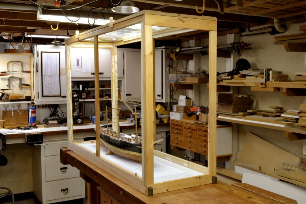
As I mentioned earlier, the framing was made from scrap, so it is not fine furniture. It is meant to be an inconspicuous part of the project – to keep dust out and allow me to take pictures of the rigging without having to drag out backdrops. Both sides are easily removable. The top is Plexiglas® sheet to pass light from the fixtures above. Six screws at the base permit the entire case to disappear.
For those who offered suggestions on covering material, thanks again. I went with Elmer's white foam board, which is what I used on the previous Victory case. It is glued to the frames with water-based contact cement. The next picture shows the port panel covered with the board.
The panel is covered with two 30x40 sheets. You may just make out the center seam. Finally, in the next picture, the completed case, with the starboard panel removed.
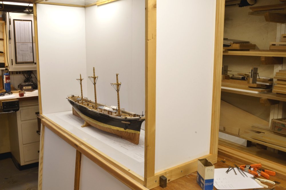
The case is certainly a major presence in the shop. Now back to the model work.
Ed
-
Hi Mike. Comments and my replies might be confusing. I am going to use foam board, 1/4" Elmer's white, which is what I used on the Victory dust case about 10 years ago. I do not want to use slotted frames this time because I don't want the frames to be visible inside - no inside fasteners either - so the foam board will be glued to the insides of the frames in a way to minimize showing corners and joints. I should have this done in a few days and will show some pics.
Ed
- Stuntflyer, mtaylor, Piet and 1 other
-
 4
4
-
-
-
Thanks for the suggestions, guys. Fabric seems a logical choice. I did not consider this because I did not want the weave as a photo backdrop. I take so many pictures for the blog and the books that I do not want to tinker with getting the backdrop out of focus on each shot. I take almost all at maximum depth of field. Also, fabric collects dust and is not impervious to fine sanding dust that is ever present in my combination shipyard/woodworking shop. The corners need to be inconspicuous , but the side panels must be easily removable to work on the model, so wrapping clothing over the inside corners won't work. The idea I had for paper corners did not work as well as I had hoped. Fabric must also be stretched to avoid wrinkles, so the frames would need to be heavier to keep straight and seal at the sides. I used foam board for the Victory case, which, unfortunately is too small for this model. It is durable, can easily be wiped down, can be fit tightly at the corners, and, I hope, the center seams on the large (60" x 38") side panels can be masked in some way. So, I always had a solution, but thought I could go cheap with that large roll of paper on hand. Never works. I also confess to perhaps overthinking the problem - something I'm good at.
Ed
-
Young America - extreme clipper 1853
Part 202 – More of the same - TopsSeeing pictures of Young America's tops may be getting tedious, but repetition is the soul of ship modeling, so I will show some more. There is not much else to do at this stage. First are the six mizzen top deadeyes, almost ready to be installed.
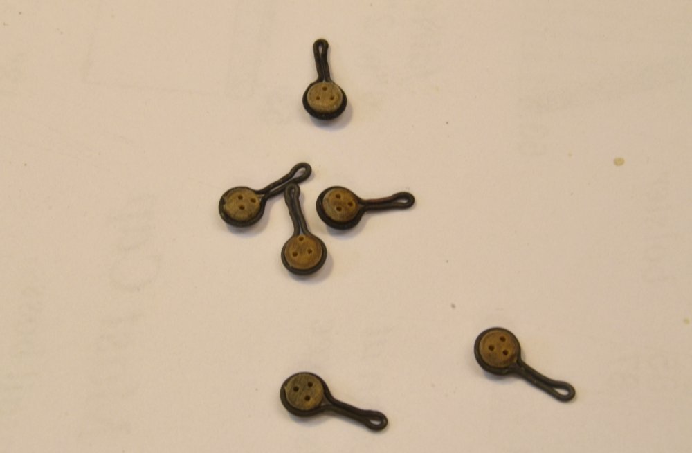
These are 8" (~.11" in diameter) – not the smallest. There are some 6". These were dyed, finished with Tung oil, and then drilled. This keeps the heavy soak in oil from clogging holes. In the picture they have just dried after dipping in LOS with their straps attached. They will get a light buffing with Tung before being fitted. I've tried different sequences. This seems to be the best.
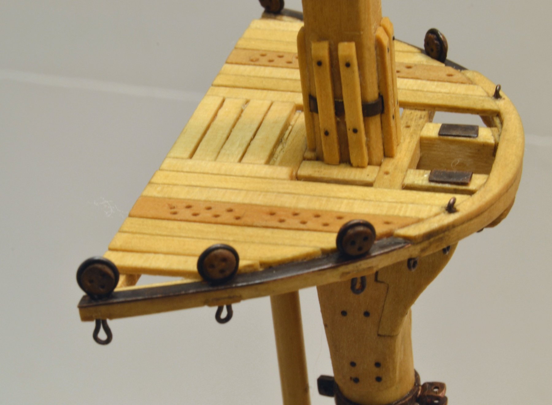
The next picture shows these - after some more finishing - installed in the rim of the top.

The top and mast head have been trimmed out with bands, eyebolts, topmast fid plates, and chafing battens. The next picture is a view from astern.
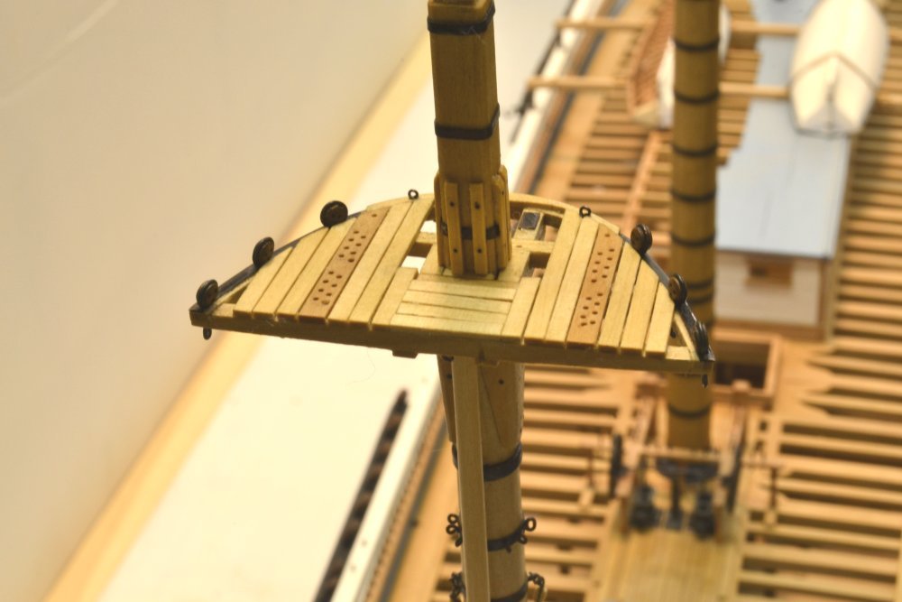
And finally, the full lower mast from above.
The next picture shows the foretop with the roughed-out mast cap fitted.
These are coming up on the agenda. They have some interesting ironwork for the lower topsail yard fittings and for the lower yard topping lift block fastenings.
All is at a bit of a standstill however, as the shipyard has become a woodworking shop for a few days as may be seen below.
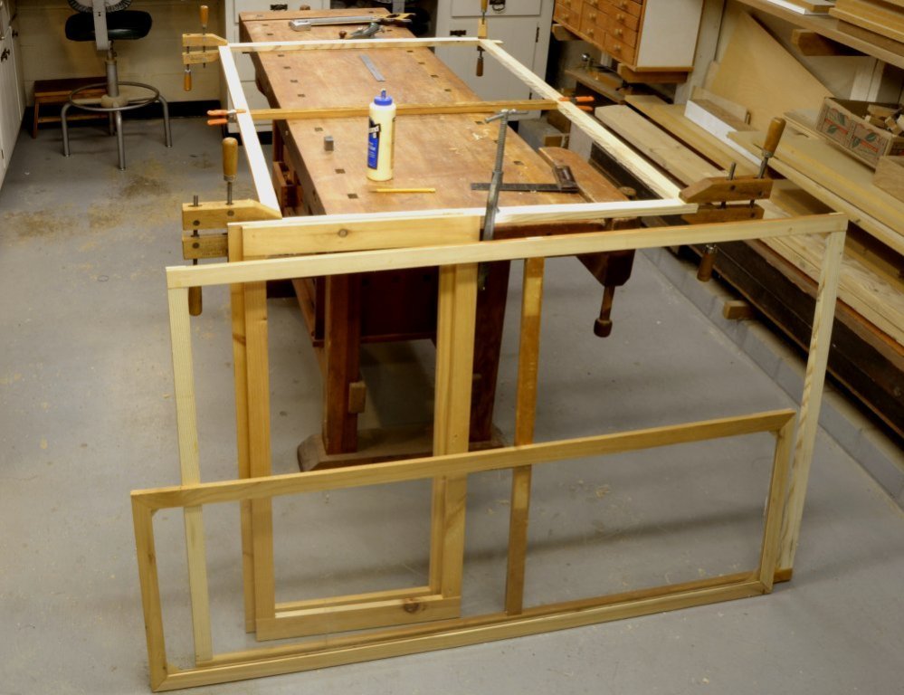
These are the frames for the dust case mentioned in an earlier post. It will also serve as an ever-present photo background for the rigging work. Its turning into one of those projects that lasts, because of trying to do it on the cheap. The wood is scrap from my collection – not a problem – but the plan was to use less expensive photo background paper over it, instead of the foam board I used on Victory – until one newly papered frame got punctured leaning against a not-too-sharp corner and a floor broom tipped over and fell through one. Foam board is on order ($50). Stay tuned.
Ed
-
Thanks, E&T and others for the likes,
Bob, you are more scientific than I am. I put about 1/8" of water in a small plastic bathroom cup, dip a small brush in LOS gel, and then stir it around in the cup, then use it immediately - either brushing it on or dropping small parts into the cup. Color of the clear solution is my measure - not too dark.
Ed.
-
Terrific work, Frank. Its great to see some of these methods applied to a completely different type of hull structure. Two Sherlines! This is serious mobilization.
Ed
- michael mott, Omega1234, mtaylor and 5 others
-
8
-
Bob,
I have found that copper can be blackened with LOS without effecting surrounding wood. The wood needs to be clean of any metal sanding dust and the LOS needs to be fairly dilute. When leveling off boltheads, files produce less fine dust than sanding but the surface should be wiped clean before treating. LOS solutions seem to neutralize to water and inert white solids and leave no reactive residues, unlike salt based blackeners like the blue selenium based solutions. You may also wish to rinse with clean water. While I have found this to be the case, some testing is always worthwhile to understand the right LOS dilution as well as the need for pre-cleaning.
Ed
-
Lovely work, Micheal. A lot of neat stuff here. I like the sawing clamp with the knurled knobs - a good idea for aging fingers like mine.
Ed
- thibaultron, michael mott, Chasseur and 2 others
-
5
-
-
Young America - extreme clipper 1853
Part 201 – Lower Mast CoatsWhen I decided to wedge the masts with pieced wedges, it was clear that some sort of mast coats would be required to cover the openings between wedges – not to keep out water as in real life practice, but to simulate the real coats and to improve the appearance at the bases of the masts.
Apart from terse descriptions, there was not a lot to go on in making these. My usual search through photos gave some ideas, but ultimately the solution came from the question, "What would I do to make a watertight canvas 'flashing' over the mast wedges?" I am comforted by the thought that many ships' carpenters asked similar questions – and came up with a variety of solutions - as the few pictures I have seen illustrate.
The canvas for the model coats is tissue and in the first picture a strip of this is being wound around the glue-coated main mast and its wedging.
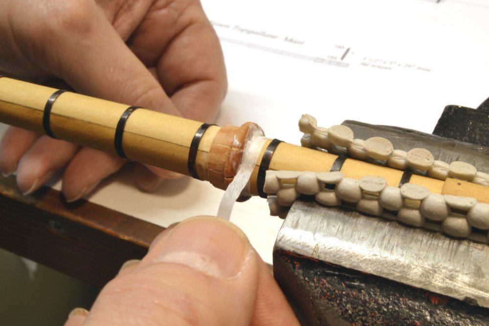
Several strips were used with plenty of glue and not too much effort to smooth out the result. Canvas would most definitely have wrinkles when forced into the required shape. The next picture shows rope being tied around the top to clinch it tightly around the mast.
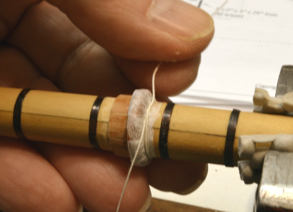
In practice the coat would have been caulked and tacked around the mast and deck, but rope cinches would keep it from tearing out from the nails and risking damage to the high-value cargo these ships often carried.
At the bottom, a flange was simulated using card and fitted around the mast at the base as shown in the next picture.
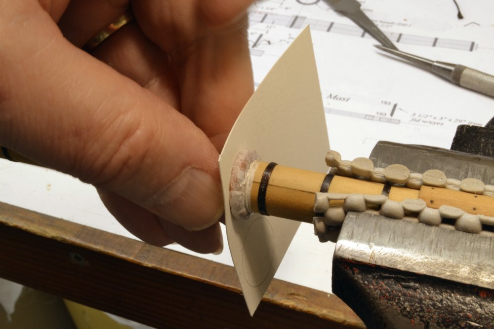
When this was glued in place and allowed to dry, a second rope cinch was added at the base. The next picture shows the coat being "tarred" with fairly thick, dark grey, artists' acrylic paint,
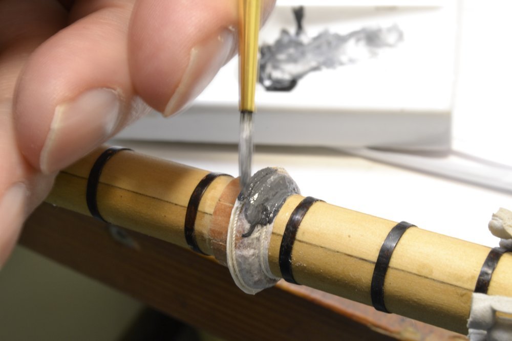
After drying the coat was brushed with black, thinned, acrylic wash to highlight the wrinkles in the canvas and the ropes as shown below.
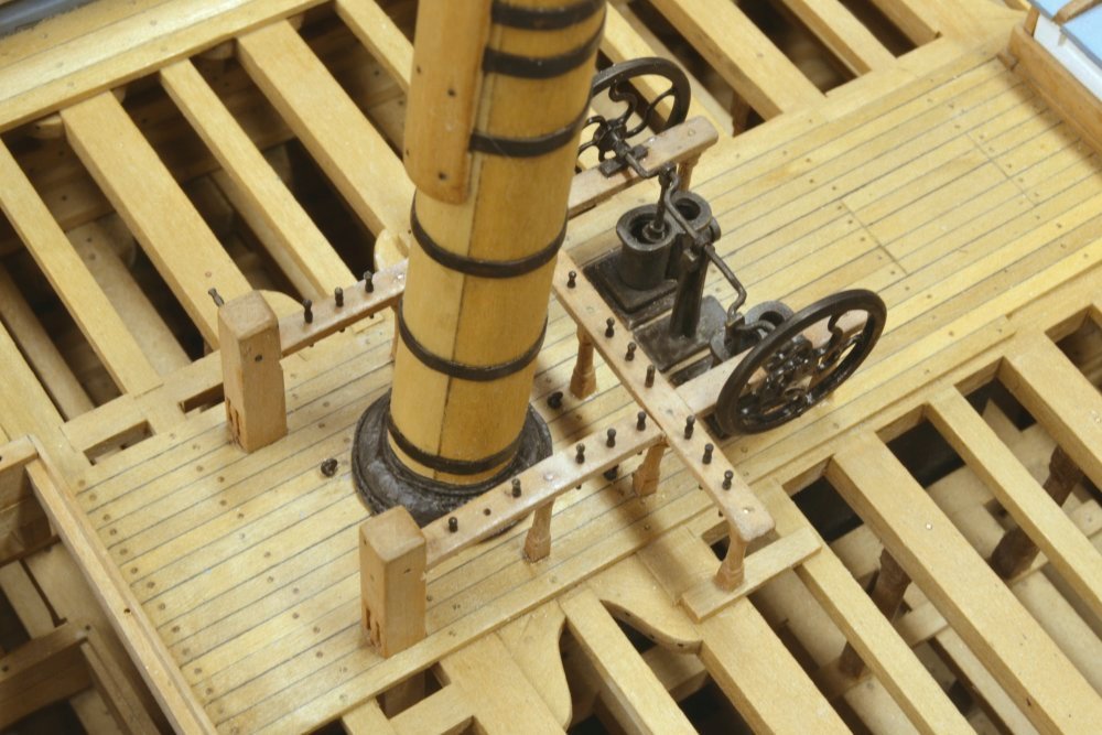
Those that have been following the project will note that the glistening brass pump wheels, by now well tarnished and lacking their original appeal, have been painted. Next job for the painters, the equally tarnished poop monkey rail.
Other true followers may also notice in the picture that I have finally gotten around to adding the central posts to the fore and aft fife rails that were previously omitted.
Ed
- John Allen, Jack12477, Dubz and 42 others
-
45
-
-
Thanks, everyone. I really appreciate the comments.
No secrets, Micheal. I'll include a picture or two in the next post, when I do the coat for the main mast. Basically just tissue, paper, some rope, glue and some tar (ie black artist acrylic).
Maury, the short answer is I do not know the specific reason for cabins. I might speculate that rope would be subject to constant rubbing and potential failure as these 30' boats shifted back and forth. These ships were equipped for the Cape. As to the reference, I undoubtedly saw this in a photo and it stuck. If I come across it I will report.
Greg, I had in my mind that it was 2 1/2 years. It actually feels like about 1 1/2. Question is, how many more will it take?
Ed
- michael mott, Piet, dvm27 and 3 others
-
6
-
Young America - extreme clipper 1853
Part 200 – Lower Masts ContinuedIt is hard to believe we are at the 200th post on Young America – almost 3 ½ years into the project. Still as exciting as ever – for me at least.
Since beginning work on the lower masts, most of the reporting has been on the fore mast – the guinea pig for construction, finishing and rigging – and only one version in the scrap box. However, though mostly unseen, work has been proceeding on the other two, so here are a few pics. The first is the most recent, taken yesterday and showing the main mast ready for fitting the deadeyes and rigging the futtock shrouds.
The mizzen mast to the left is almost to the same state, but needs its masthead detailing. The next picture shows the main top before fitting the deadeyes.
At 18' 6" in breadth, this is somewhat larger than the 17' fore top. The "pre-rigging on this top includes a pair of brace blocks for the mizzen lower yard, the crojack. These may be seen dangling from shackles below the aft crosstree. Because of the soldered shackles, any shackled connections, including eyebolts, need to be either fitted with their blocks or left off until later.
The next picture shows the forward chafing batten being glued to the mizzen mast.
The batten is concave on the mast face and was rounded on the forward face after gluing. The top, with the 9" diameter spanker mast inserted, is to the lower left. The below-deck rings have been blackened and the ring of wedges is in place. After this step the above deck ironwork was buffed with a clean wheel and blackened as shown in the next picture.

The sanding stick in the picture was used to clean the glue off the batten's nail heads (not shown). The next picture shows the mizzen at this stage.
The top and the spanker mast are permanently attached in this picture. The picture also shows small brail blocks hanging from the mast. These will be discussed later.
By this time, the foremast was complete and could, if desired, be permanently installed. The last picture its base with a mast coat fitted over the wedges.
The mast coat simulates a tarred canvas cover with surrounding rope to pull it tight at the mast and at the base. It would also have been nailed before tarring. I could find no standard method for these – only brief and varied descriptions.
Ed
-
-
Rob, as I said in the last post, the shrouds are given an initial tension - after hooking - by the lashings at the mast. These lashings consist of 6 turns of small rope that allow the shroud to be pulled straight when they are hauled up. the lashings are then secured by wrapping the rope around the turns and securing it. Although visibly straight at this stage the futtock shrouds will not be put under tension until the topmast shrouds are tensioned and secured using their deadeye lanyards. The deadeye straps have a sliding connection at the rim of the top so that this tension can be applied from the topmast head to the lower mast eyes through each futtock and shroud. If either shroud were fixed at the top, that light structure would be subject to failure from bending forces at the rim. With the sliding connection at the rim the top cross trees are only subject to horizontal compression. Clear?
Ed
-
Rob,
The specified shroud size is now 5 1/4" (actually closer to 5.5" model rope) and the deadeye size is 9". Rule of thumb is 1.5X, but sources show 9" up to 10" for these. The hooks are not adjustable. The futtock shrouds are given an initial tension by the lashings at the mast, but the real tension in the futtocks will be applied when the lanyards on the topmast shrouds are are hauled up. The lower shrouds will be paired 1&2, 3&4, 5&6, which I believe is standard.
Ed
- Mirabell61, mtaylor, Capt.Bob and 2 others
-
5

Young America 1853 by EdT - FINISHED - extreme clipper
in - Build logs for subjects built 1851 - 1900
Posted
Thank you, Jack. The photo store comment was a bit of gallows humor lamenting the loss of actual stores like that. We are as guilty as any, with UPS and Fedex drivers wearing a path to our front door almost daily.
Ed