druxey
-
Posts
13,353 -
Joined
-
Last visited
Content Type
Profiles
Forums
Gallery
Events
Everything posted by druxey
-
 The secondary pay-off is the increased headroom aft under the quarter deck! A couple of inches would make a difference between having to duck under the beams or not!
 -
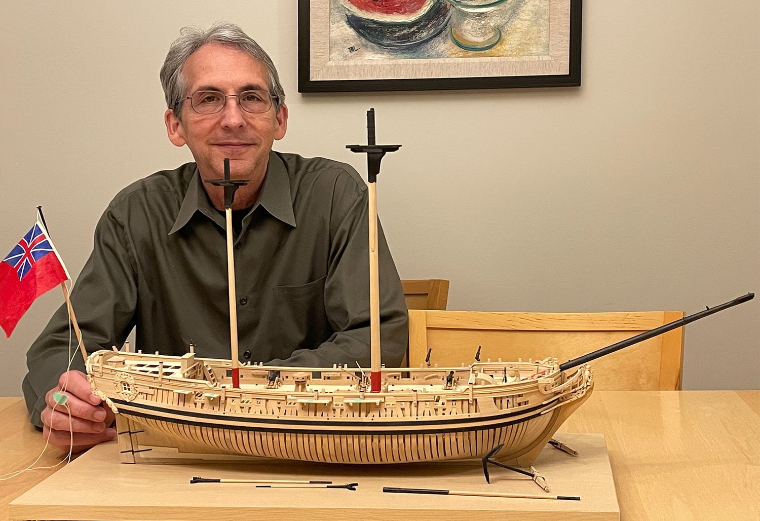
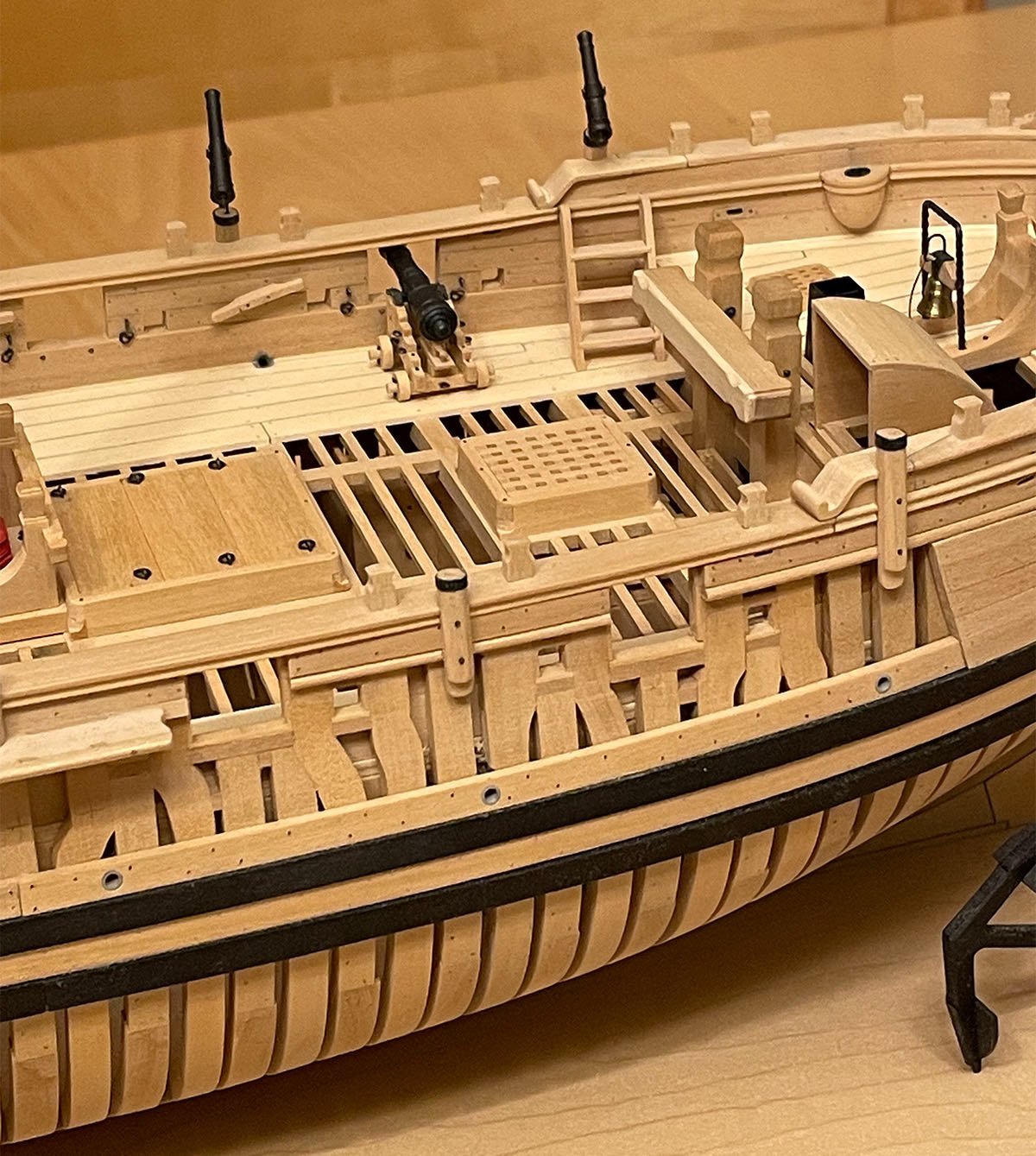
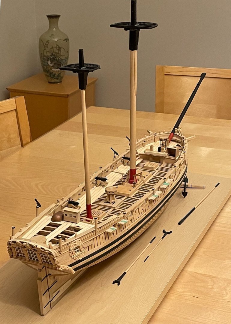
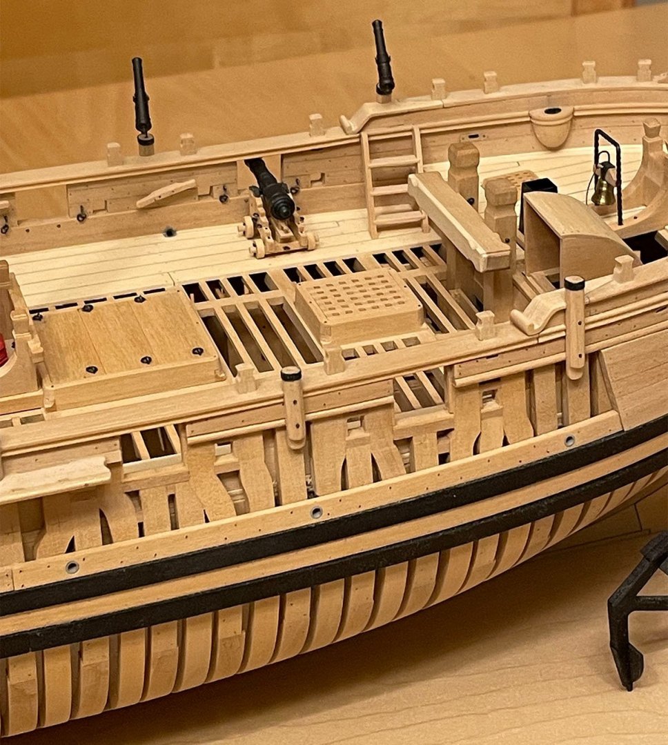
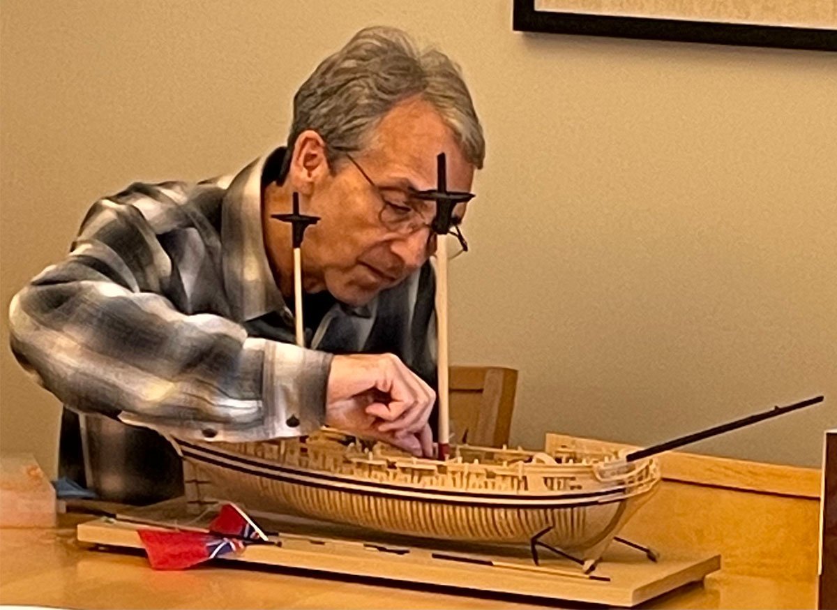
Finally, after a wait of almost three years, Greg Herbert was able to travel this weekend and retrieve Speedwell from David Antscherl's workshop. The model had been marooned in Canada due to covid after having the carved works made and fitted. Speedwell (she was temporarily re-christened Speednaught) is now heading back to Maryland with her rightful owner for rigging. The saga will continue soon.... Photos of the reunion are attached.


-
The gap is deliberately there so that water can drain through!
- 23 replies
-
- 5
-

-

-
- Lowell Grand Banks Dory
- Model Shipways
- (and 1 more)
-
Welcome aboard, Paul. Check out the Marine Modellers of Niagara in the 'clubs' section of MSW.
-
Look at some of the planking tutorials on this site!
-
Where can I find metal wire?
druxey replied to flying_dutchman2's topic in Metal Work, Soldering and Metal Fittings
Might I recommend not using steel or iron wire - it may rust. Use either brass or copper wire. To get rid of shine, either lightly sand with fine (400 grit) paper or, better, use a coloring agent such as the Jax range of chemical colorants: https://jaxchemical.com/product-category/colorants/ -
What exactly are you trying to waterproof? Is this for a floating model hull, or just to prepare for painting a wood surface?
-
After all those spider band sketches you are still sane, Keith? That must have been quite a job figuring them out. Nice boots, BTW!
-
Impressive work so far, Oliver. This looks lovely in pearwood.
-
Coming along? It certainly is! Your castle structures are a triumph of patience over adversity.
-
Search: 'miniature left hand thread taps and dies' One result: https://www.etsy.com/ca/listing/204960886/14-tap-die-set-no-07mm-to-2mm-taps-and?gpla=1&gao=1&&utm_source=google&utm_medium=cpc&utm_campaign=shopping_ca_en_ca_b-craft_supplies_and_tools-other&utm_custom1=_k_CjwKCAjwk6-LBhBZEiwAOUUDpxEIaD5B28Q7qqb-p0gWEGwFt6zgynsLWc3OKAnMrgGdG1AHY9PXShoC6DEQAvD_BwE_k_&utm_content=go_319629165_19444327605_75295112325_aud-310388264614:pla-106551294035_c__204960886enca_367792477&utm_custom2=319629165&gclid=CjwKCAjwk6-LBhBZEiwAOUUDpxEIaD5B28Q7qqb-p0gWEGwFt6zgynsLWc3OKAnMrgGdG1AHY9PXShoC6DEQAvD_BwE Happy hunting!
-
Welcome aboard, Alex.
-
At this point you realize how amazingly complex wood engineering was back then. Looking good, Kevin!
-
I somehow missed seeing this thread until now. Please take every post as 'liked', Johann. Your work continues to be exceptional!
-
You will need to set up the hawse timbers, mark out the lines of the filling pieces and individually fit them between the timbers without pushing them out of alignment. Have fun!
-
Perhaps a pedantic point, but the Steel you refer to has no 'e' at the end of his surname. I mention this as a Steele with an 'e also wrote a naval architecture in 1917. This can cause confusion between David Steel (1805) and the later J.E. Steele.
-
Cheers from Port Hope, Ontario, Canada
druxey replied to Peter Rumgay's topic in New member Introductions
Welcome, Peter. Check out the Marine Modellers of Niagara on the 'clubs' section of MSW. -
Nice going, JD. I find that by making the planks a little 'full', when a strake is complete I sand the 'free' edge smooth with a flexible sanding stick to create a perfectly even line for the next strake.
-
Oh, I'm sure you'll do a nice job on the kit 'as is'. But you may feel you want to kit bash a different kit later on.... Just sayin'!
-
Life happens! We understand, You'll get back to it when you can.
-
Your comments on the kit scale fitting out make me think you are on your way to either kit-bashing (modifying the model as you build it) or even scratch building!
- 109 replies
-
- 2
-
-
- Finished
- Artesania Latina
- (and 1 more)