


druxey
-
Posts
13,362 -
Joined
-
Last visited
Content Type
Profiles
Forums
Gallery
Events
Everything posted by druxey
-
 You will need to set up the hawse timbers, mark out the lines of the filling pieces and individually fit them between the timbers without pushing them out of alignment. Have fun!
 -
Perhaps a pedantic point, but the Steel you refer to has no 'e' at the end of his surname. I mention this as a Steele with an 'e also wrote a naval architecture in 1917. This can cause confusion between David Steel (1805) and the later J.E. Steele.
-
Cheers from Port Hope, Ontario, Canada
druxey replied to Peter Rumgay's topic in New member Introductions
Welcome, Peter. Check out the Marine Modellers of Niagara on the 'clubs' section of MSW. -
Nice going, JD. I find that by making the planks a little 'full', when a strake is complete I sand the 'free' edge smooth with a flexible sanding stick to create a perfectly even line for the next strake.
-
Oh, I'm sure you'll do a nice job on the kit 'as is'. But you may feel you want to kit bash a different kit later on.... Just sayin'!
-
Life happens! We understand, You'll get back to it when you can.
-
Your comments on the kit scale fitting out make me think you are on your way to either kit-bashing (modifying the model as you build it) or even scratch building!
- 109 replies
-
- 2
-

-
- Finished
- Artesania Latina
- (and 1 more)
-
Again, caution should be taken as many models with 'original' rigging have been repaired over time and not all the lines may be OEM!
-
If you must use wire wool, use bronze not steel for the reasons given above. However, it's hard to find these days.
-
That is one of the critical points in forming the quarter gallery; everything is parallel to each other. You should be fine from here on.
- 399 replies
-
- 3
-
-
- winchelsea
- Syren Ship Model Company
- (and 1 more)
-
Ships name 1700s
druxey replied to DaveBaxt's topic in Discussion for a Ship's Deck Furniture, Guns, boats and other Fittings
B. E.: I know that the French usually showed the ship's name in a compartment on the counter, but was not aware of this being done by the British in the early 19th century. Victory's name was certainly seen this way in early 1900's photographs (below), and persisted until changed to something more appropriate recently.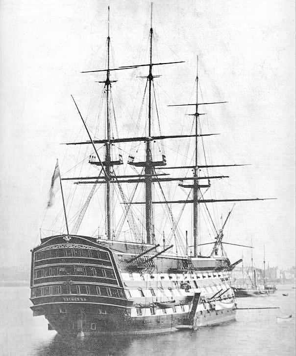
-
Wet and dry paper is used for metal, not wood. This, and the fact you are using extremely fine grades is why you are getting clogging. Garnet, emery, aluminum oxide and silicon carbide are used on wood. See: https://www.empireabrasives.com/blog/sandpaper-grit/ Usually, for wood, 400-grit is as fine as you need to go.
- 21 replies
-
- 11
-
-
Best wishes as you manage an elderly parent. It's never easy.
- 2,699 replies
-
- 3
-
-
- heller
- soleil royal
- (and 9 more)
-
It is see-through, peels off easily and has a matte surface that takes a fine pencil line.
-
Ships name 1700s
druxey replied to DaveBaxt's topic in Discussion for a Ship's Deck Furniture, Guns, boats and other Fittings
British ships' names appeared across their counters officially in 1772, although this may have formally been done for a few years earlier. The practice seems to have been discontinued during the Napoleonic wars. -
A lovely result, Giampiero.
-
Soft, medium or stiff brushes?
druxey replied to CPDDET's topic in Painting, finishing and weathering products and techniques
Look after a good quality sable and it will last you years. I have some over 30 years old and they are still in good shape. Cheap brushes are a snare and delusion. You have to keep buying them over and over and they will shed hairs in your beautiful fresh coat of paint! -
Nice progress, Maury. I assume the rest of the model will be weathered eventually?
-
I find Scotch Matte Removable tape even better than masking tape for the purpose.
-
Swan-Class Sloop by Stuglo - FINISHED - 1:48
druxey replied to stuglo's topic in - Build logs for subjects built 1751 - 1800
The illustration shows full-size practice. You can cheat, as long as the end-result looks right. -
Glad you had such a good time. I'm so sorry that I had to miss the great showing this time. U.S.: Why you no open land border to nice, polite, vaccinated Canadians?
- 2,699 replies
-
- 4
-
-
- heller
- soleil royal
- (and 9 more)
