druxey
-
Posts
13,090 -
Joined
-
Last visited
Content Type
Profiles
Forums
Gallery
Events
Everything posted by druxey
-
The storm was recorded on 14th August. Fly was recorded as 'foundered' off Newfoundland in 1802; no specific date given, but 'spring'. So this could not have been the same event.
-
Quick thinking, cool heads and a narrow escape!
-
 The fish davit is seen deployed on the port side having just fished the anchor there. (The model is a modern one of Resolution of 1777-78).
-
For my models, it never takes long to file down two opposite faces of the hex nut so there is some 'meat' left on both sides of the keel. Each to their own....
-
It was announced some time ago that the owner, Bob Friedmann, has had some significant health issues. This is the most likely reason for delay in deliveries. I hope that he is continuing to recover and that folk will have some patience. He has been a stalwart in supporting the ship modelling and research community as well as his authors for many years.
-
"The model was altered sometime in the 19th century". My suspicions are confirmed! Belaying pins were certainly in use by the 1630's in Sweden. Primary evidence is seen in the headwork of Vasa. See: https://www.google.com/search?q=vasa+head&tbm=isch&ved=2ahUKEwilsfzSv8TnAhUa_qwKHT9qCzYQ2-cCegQIABAA&oq=vasa+head&gs_l=img.12..0i24l2.154814.154814..156960...0.0..0.89.89.1......0....1..gws-wiz-img.eAZ-oODLVXU&ei=lf4_XuWSCJr8swW_1K2wAw&bih=1094&biw=1651#imgrc=aiE6P9-LMhO8hM&imgdii=EReBgpq4OggxJM
-
Looks like you have absolutely the right mind-set and approach to building. Most 'newbies' rush into things. You are thinking ahead and anticipating - exactly the right attitude. You'll do well!
-
15 ½? (One cannon is half in view, upright.) This is an interesting image. Thank you for bringing it to our attention, Bruce.
-
Welcome back, Dana! Depending on the hull form, a bulwark rabbeted into it is one approach. Another might be stanchions inset into the hull sides, then planked in some way.
-
Those pins on the open rail, regardless, are an outlier. I cannot recall seeing this arrangement on any other model.
-
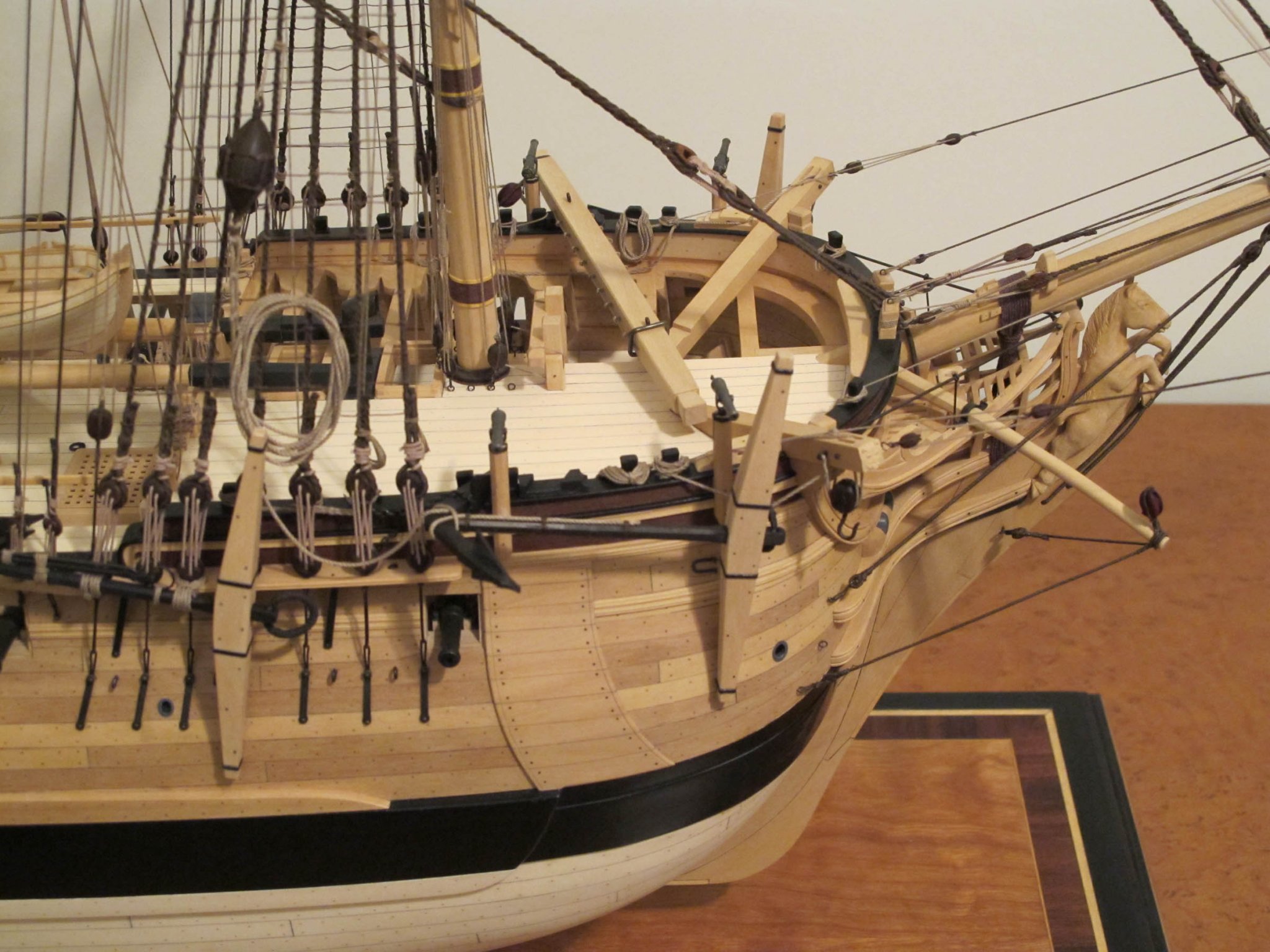
From the RMG Collections site. Unfortunately the image is not available: DIC0047 Description Scale: 1:48. Plan showing the bow, headrails and figurehead for Centaur (1797), a 74-gun Third Rate, two-decker. The colour washed figurehead depicts a full-length centaur rearing up on his hind legs with a raised club in his right hand. A cloak, reminiscent of a horse’s mane, cascades down his back and over his flanks. The trail-board includes a conical quiver of arrows and a bow, surrounded by oak leaves and acorns. Signed by John Marshall [Master Shipwright, Plymouth Dockyard, 1795-1801]. This could be one of a number of proposals for the Centaur’s figurehead as the top left includes the annotation ‘No. 1’. See sketch DIC0080 for unsigned and undated version of this sketch, and sketch DIC0001 for a possible port side version. Date made 1 July 1800
-
I must be thick, but why do you need to do all this? If I understand what you are trying to do, would not a threaded insert do the job? Or am I missing something?
-
Ingenious solution and a great result!
-
No period after the url, Dave. Just: dvm27@comcast.net
-
How much of that 1650's model rigging is contemporary? Looking at it, I'm a bit suspicious.
-
'Trumpet' here (post #43) is not the brass instrument, but the man who was a trumpeter! Later (1811) the post of trumpet major was instituted. Thomas Hardy wrote a novel of that name. I had to read that in school and it was deadly dull!
-
Nice simplification, Toni! Gratings look great. Before you do the weather decks, you might want to check the pattern of your butt shifts. (That didn't sound quite right. You know what I meant!)
-
You're getting there, Rob! Won't be long before the launching ceremony....
- 1,208 replies
-
- 3
-

-
- great republic
- clipper
- (and 1 more)
-
Workshop Essentials - Favorite Features
druxey replied to Justin P.'s topic in Modeling tools and Workshop Equipment
Leave enough pass space for a chair with you seated on it! -
Ah, the rabbit-hole of research! Ain't it fun? Glad to read that your back is better.
-
For a smaller ship, the last illustration, left side, is about right; other than a one-piece cheek and bibb combined.