


druxey
-
Posts
13,369 -
Joined
-
Last visited
Content Type
Profiles
Forums
Gallery
Events
Everything posted by druxey
-

Full size mizzen topmast construction pictures
druxey replied to jcoby's topic in Masting, rigging and sails
Good one! Thanks for posting this.- 1 reply
-
- 3
-

-
Nice to pick the model up again after such a lapse in time. She's looking good. I smiled when I read 'Cookham'. I spent time in the area many years ago and remember visiting Stanley Spencer's museum and Cookham Church. Lovely place.
-
Echo by Maury S - FINISHED - Cross-Section
druxey replied to Maury S's topic in - Build logs for subjects built 1751 - 1800
Further to yesterday's post, here is a photo of a baseboard that was veneered and banded using Titebond. The other advantage is that you can spot-tack the pieces in place: they don't 'grab' like contact cement. A little heat will reverse the bond so that you can reposition a piece if you need to.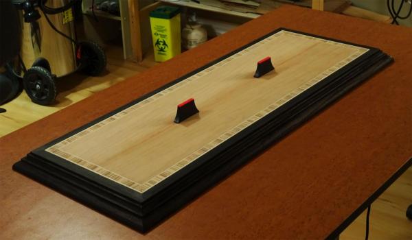
-
Nice clean looking model, Dave. It's nice that you have mentors on hand.
-
To spile or not to spile...
druxey replied to fish's topic in Building, Framing, Planking and plating a ships hull and deck
It's nice not to have to fight and wrestle planks, isn't it? -
Echo by Maury S - FINISHED - Cross-Section
druxey replied to Maury S's topic in - Build logs for subjects built 1751 - 1800
Titebond is good if used the right way! Coat both the veneer and the substrate with glue. Allow to dry. Then iron the veneer to the substrate. (Careful not to have the iron too hot. A layer of paper will act as a bit of insurance.) Works a treat, and no contact cement fumes or strings! You could try ironing your wavy veneer down, Maury. Rubber cement is not permanent, BTW/ -
Nice detail, Toni! It's amazing the number of bolts of various sorts that went into a vessel this size.
-
If one needs to paint, sanding lightly first before any solvent use would be good. Too much solvent may affect the glue in the model.
- 1,215 replies
-
- 1
-
-
- sloop
- kingfisher
- (and 1 more)
-
Ingenious operations! Like Crackers, some of this made my head spin, but I recognize your fluency in the program.
-
Part of your issue may be the thickness of the material you are using. Some modelmakers get better results using SilkSpan (model aircraft supplies).
-
Wayne: part of my issue is that Steel does not, in his glossary, define either 'stop' or 'lining' (other than 'lining out' - a completely different subject!). Thanks for the Fincham extract, as I do not have that volume. So, if I understand rightly, Fincham calls the inner layer of the port lid the lining, the pieces around the port opening the back stop or port stop. Is this definitive?
-
To spile or not to spile...
druxey replied to fish's topic in Building, Framing, Planking and plating a ships hull and deck
I haven't experimented with off-model edge-bending, Nigel. I've seen Chuck's results and they do look very good. I wonder if there will be a tendency for them to 'spring' later on, after a year or two? Similarly, how easy would it be to edge-bend a complex 'S' shaped wale plank accurately, such as shown here?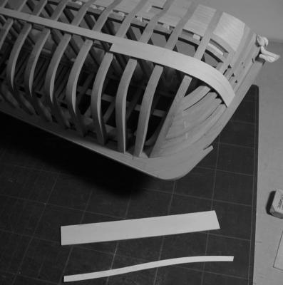
-
To spile or not to spile...
druxey replied to fish's topic in Building, Framing, Planking and plating a ships hull and deck
With all due respect, Nigel, while one can edge-bend a plank to a degree, the ideal is as Joel states; "The plank should set onto the hull with no stress, totally relaxed". It imparts a good deal of stress to edge set a plank more than a few degrees. Heat and moisture can help, for sure, but I wouldn't want to attempt edge-setting planks around a bluff bow. I tried that on an early model of mine and, after a few days, the result looked like clinker planking, except it was supposed to be carvel! -
I believe that 'linings' refers to the inner layer of plank on the port lids. These need to fit the port lid neatly into the stops, which are the pieces that form the rebate around the port on the lower sill and sides.
-
I've generally not had problems with Fiebings, except on one lot of wood where the dye uptake was blotchy and I had to paint.
- 1,215 replies
-
- 2
-
-
- sloop
- kingfisher
- (and 1 more)
-
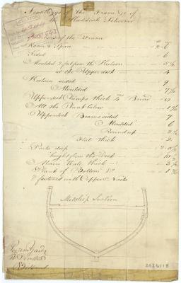
Coming into this discussion a bit late, but the rise in deckhead aft for the cabin overhead was not uncommon in smaller vessels. The step-up in Ballahoo/Haddock is a bit more unusual, but solves the same problem of restricted clearance. I note a gun port in line with this raised deck, so would not be workable. Speaking of gun ports, their sides appear to be parallel to the sheer rather than the keel - most unusual. George, were you aware of the nice section with scantlings for Haddock (ZAZ 6118) in the RMG collection?
-
Bee-utiful, Glenn! I'm getting addicted to your weekly progress postings. Might be fun to show the kludged spare cam frame....
-
Soldering dangerously close to the hull
druxey replied to popeye2sea's topic in Metal Work, Soldering and Metal Fittings
Another possible heat sink is to use a chunk of apple or potato (depending on your taste!). -
Oy! This is very exacting detective work with a high-power magnifier. I'm impressed, Ron.
-
Nice demonstration of fitting these tricky pieces, Fam. Well done!
-
The advantages and disadvantages of these two extrusion methods is very educational. Please continue!
-
Frégate d'18 par Sané , la Cornélie
druxey replied to JohnE's topic in CAD and 3D Modelling/Drafting Plans with Software
Bien fait, Monsieur! Je vous remercie pour les sabords flottants! Thanks for the 'extra' floating ports. -
Just catching up with your work, Clare. What delightful vessel! I'm sure other builders will appreciate your comments and helpful tips. Well done!
- 51 replies
-
- 4
-
-
- wasen
- thermal studio
- (and 1 more)
-
I've had a whole container turn to a solid gel, Mike.
- 969 replies
-
- 5
-
-
- hahn
- oliver cromwell
- (and 1 more)


