

.jpg.f26acc9a74319261612561bfa7da1303.jpg)
vaddoc
-
Posts
1,605 -
Joined
-
Last visited
Content Type
Profiles
Forums
Gallery
Events
Posts posted by vaddoc
-
-
2 hours ago, mtaylor said:
wouldn't the other side need sheaves
All in good time Mark! The boat is not finished!
Although here in Cambridgeshire the wind is remarkably stable😃
- mtaylor and Keith Black
-
 2
2
-
Many thanks to all for your likes and comments.
The last few days have been both busy and frustrating. Many things went wrong and correcting the issues was difficult. I also kept dropping the little complex pieces on the floor, I found most but not all so I had to re-do a few things. Then I found bigger issues.
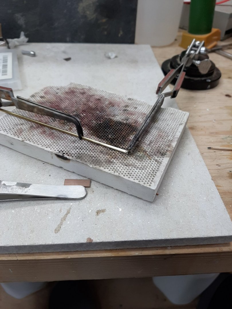
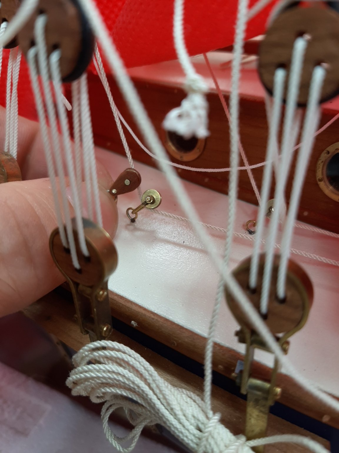
To start with, I made a few wooden sheaves. I did not want them to sit very high above the deck so I did not use shackles but used eyes directly soldered to the threaded rods. The soldering was quite tricky.
Then I replaced the metal sheaves on the port side of the deck with the wooden ones. This was a ton of work as the space is tight and also I had to take down the sheets and blocks etc and then re-do them back. And all this in a heatwave.
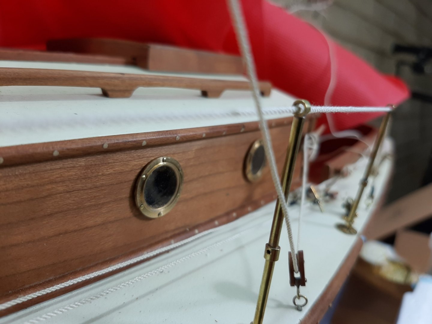
Then I installed the upper rail. After I had finished I realised it was wrong so had to redo it. Both the upper and lower rail will have a pair of hearts as tensioners. The lacing in the second pic is wrong, was corrected later

I also installed the sheet for the top jib
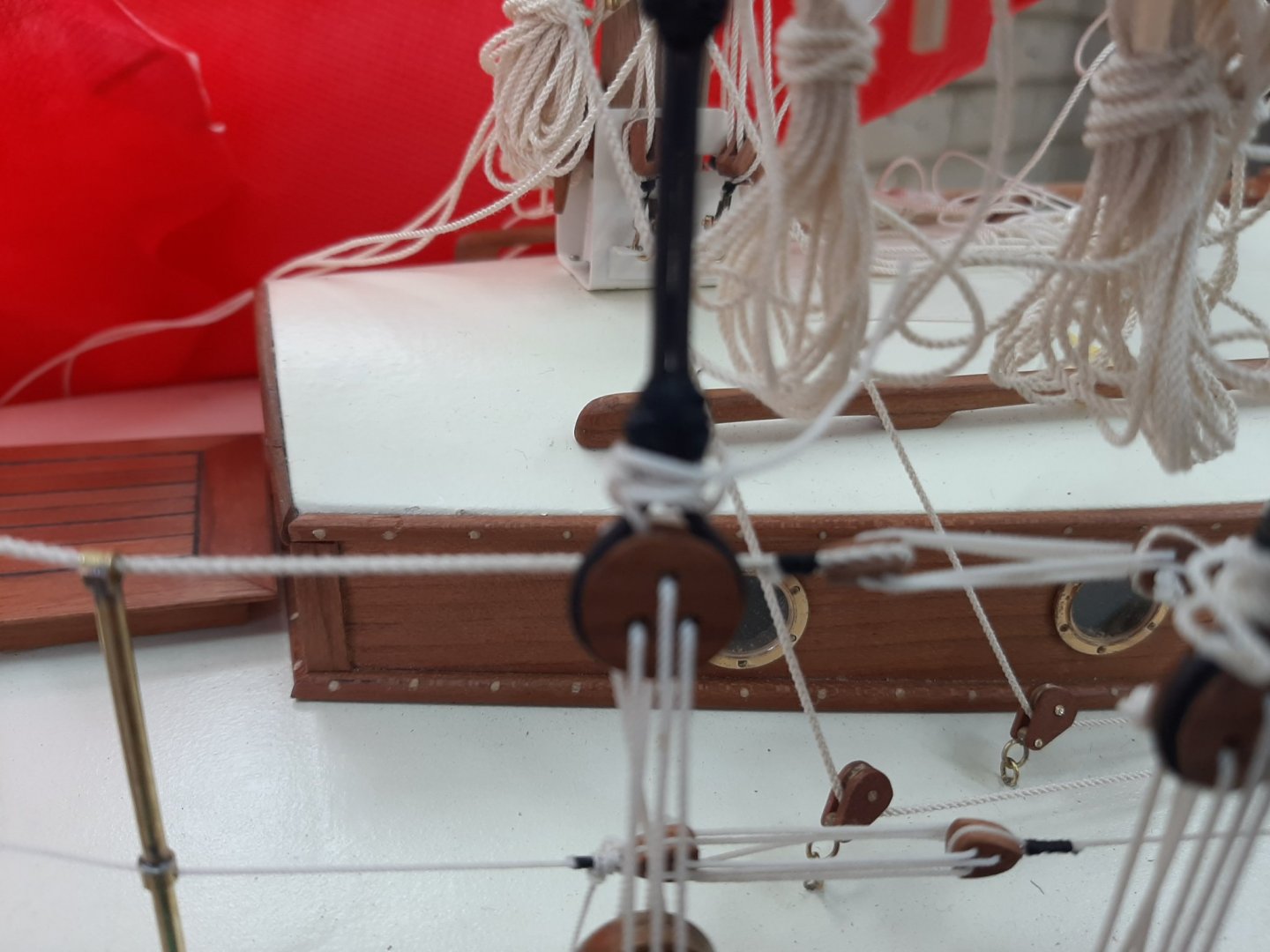
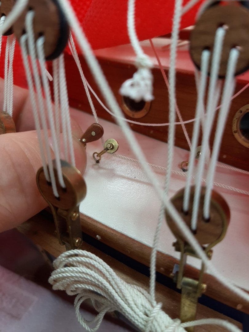
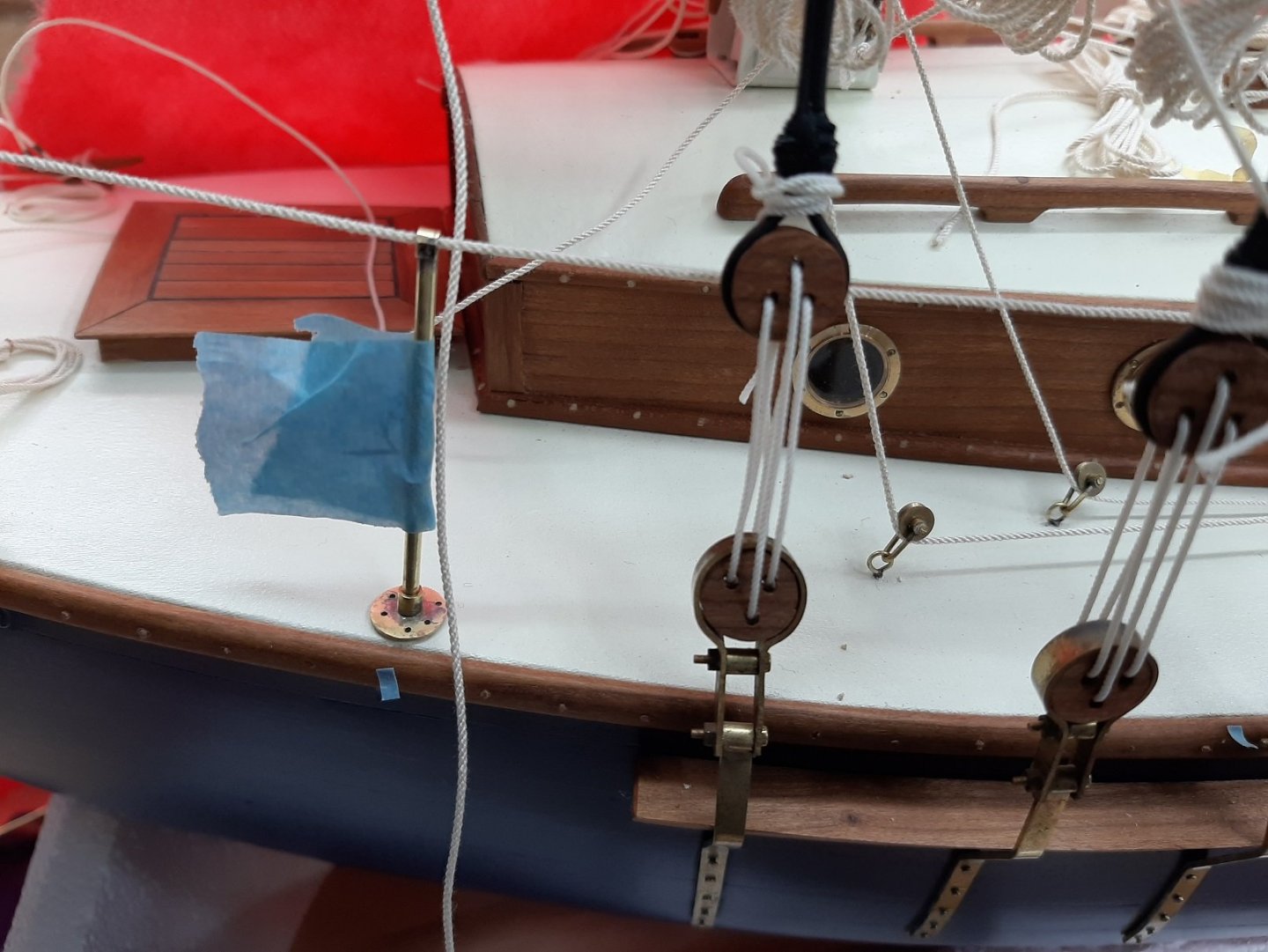
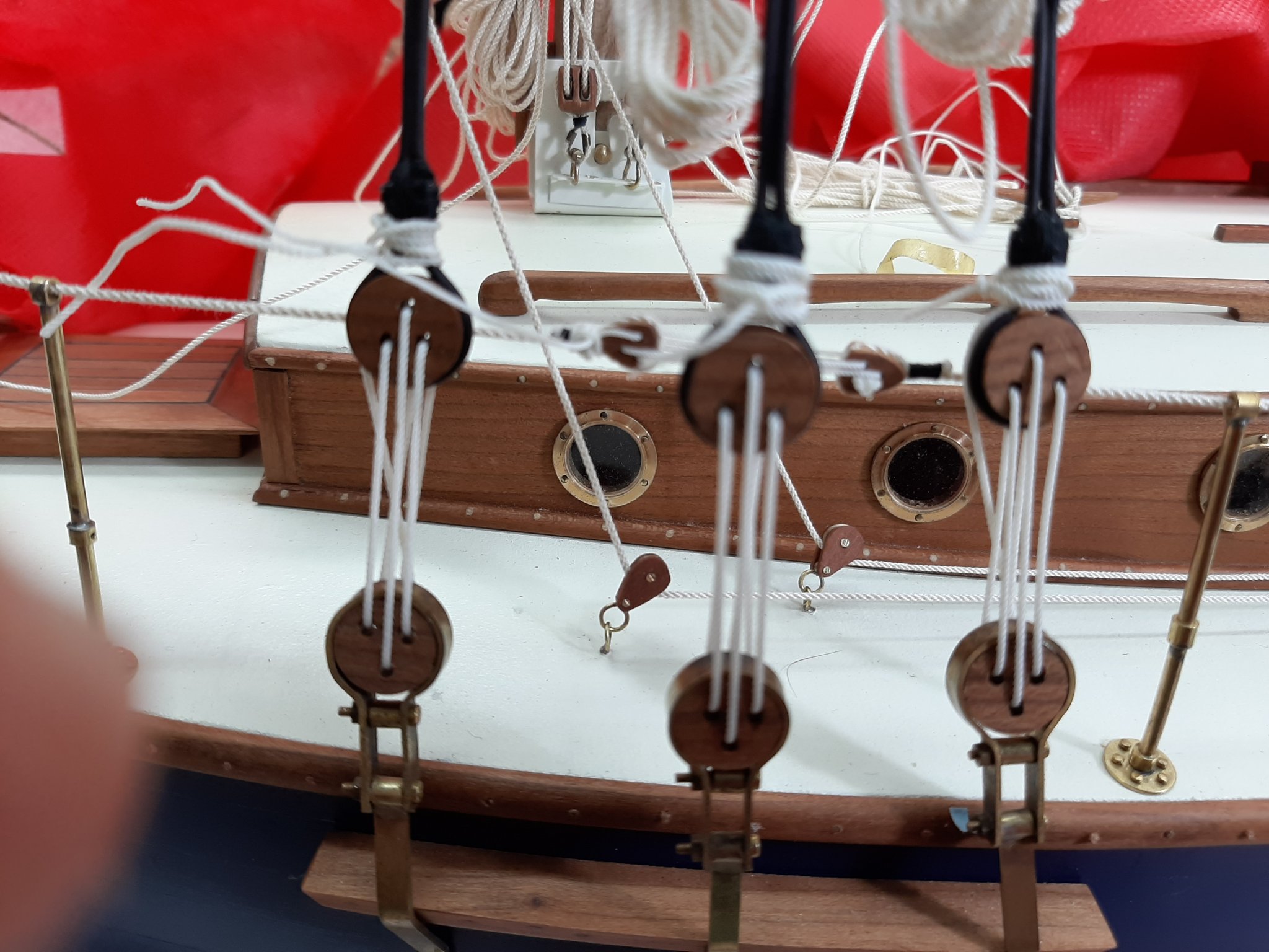
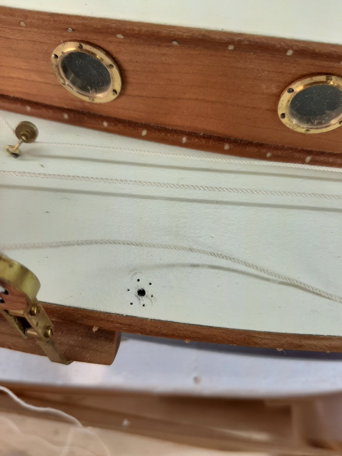
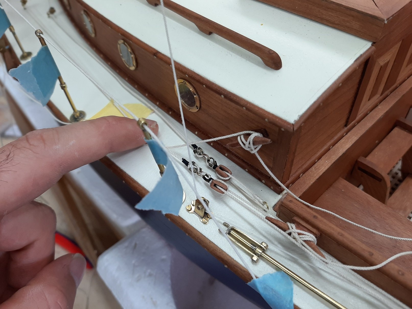
Then it was time to install the lower rail and disaster struck. The thin rope goes through holes in the poles but I had forgotten to drill through one of the poles! The next two photo show the missing hole
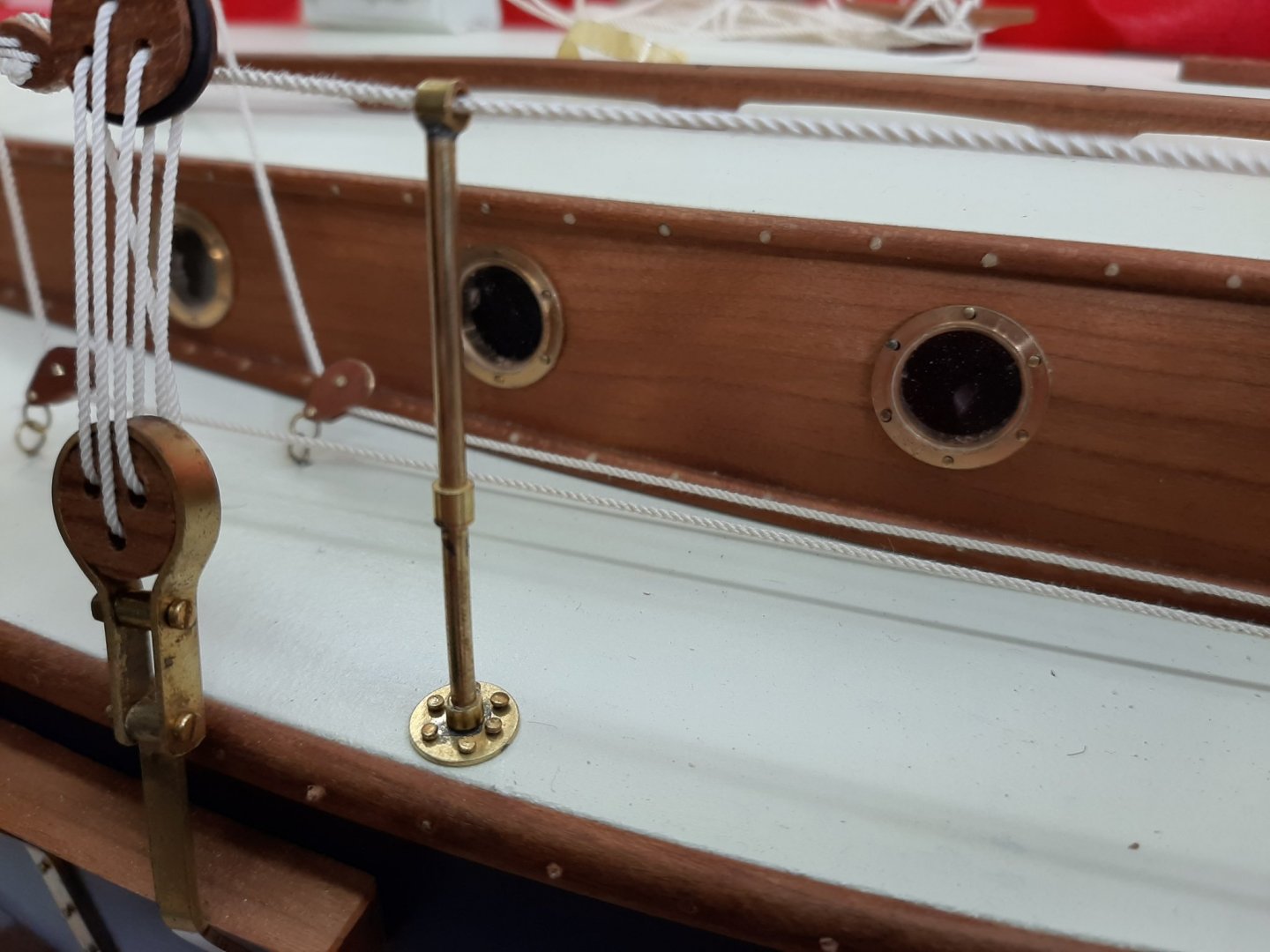
This is 3 mm solid brass and only Tungsten drills will go through. No other option, I had to take down the upper rail again, take out the pole and drill it. This went well but I checked the other 5 poles that would go on the other side and one was also not drilled. During drilling, the carbide drill broke and stayed stuck in the hole. This is game over, the piece is trash. I re-did the piece which is pretty complex and I had my first soldering failure in a long time. I managed to save it though but with a lot of work and quite a lot of cursing. The swear box must be full by now...
Then, I had to put the pole back, re-do the upper rail for the third time, then install the lower rail and call it a day.
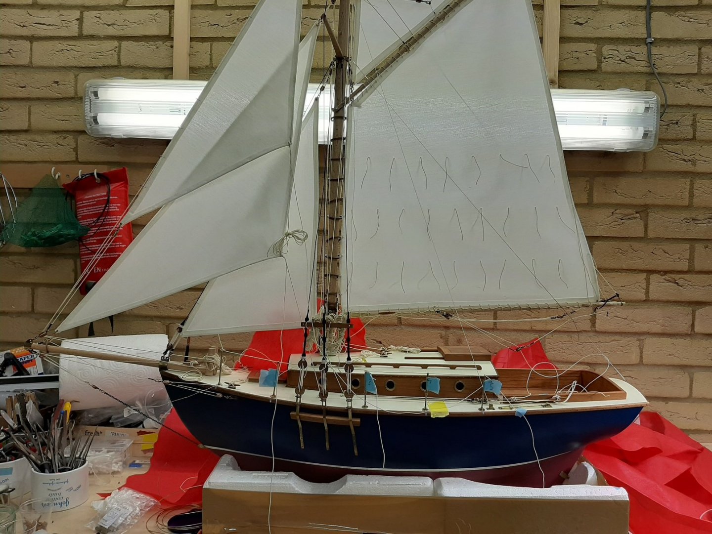
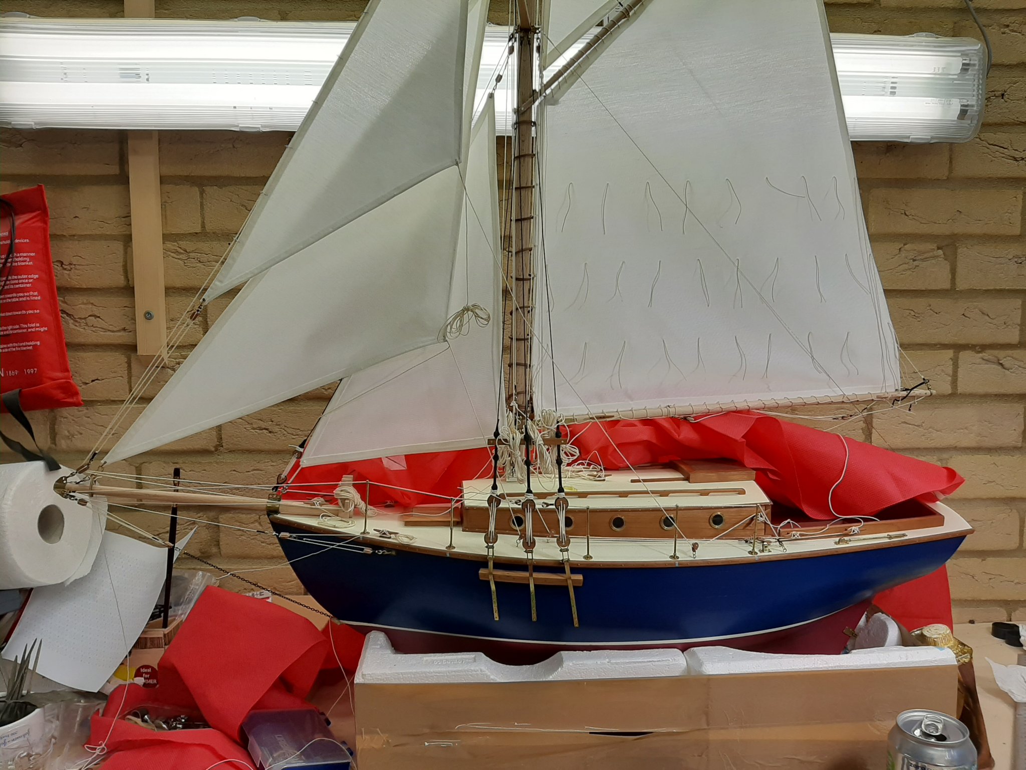
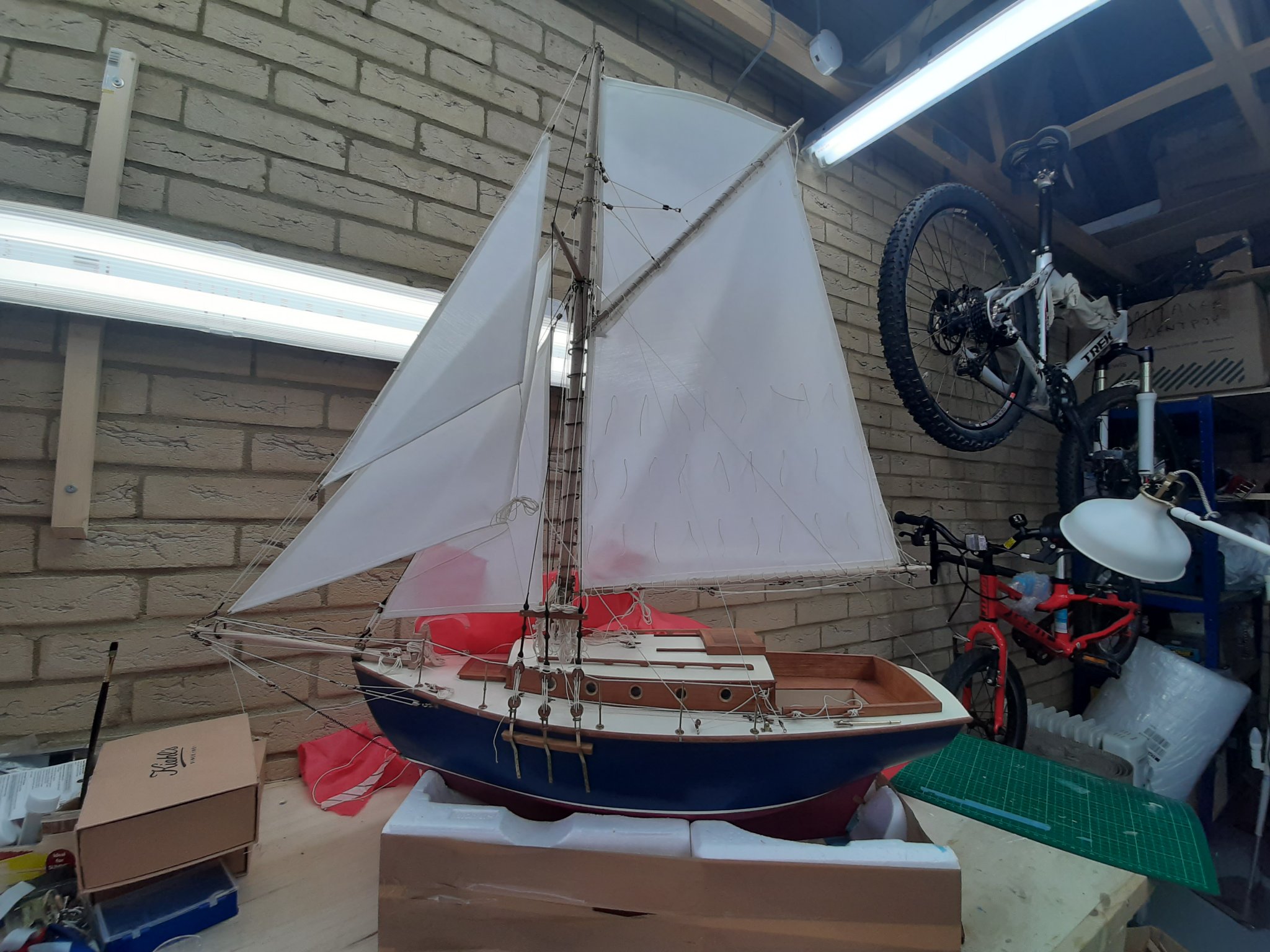
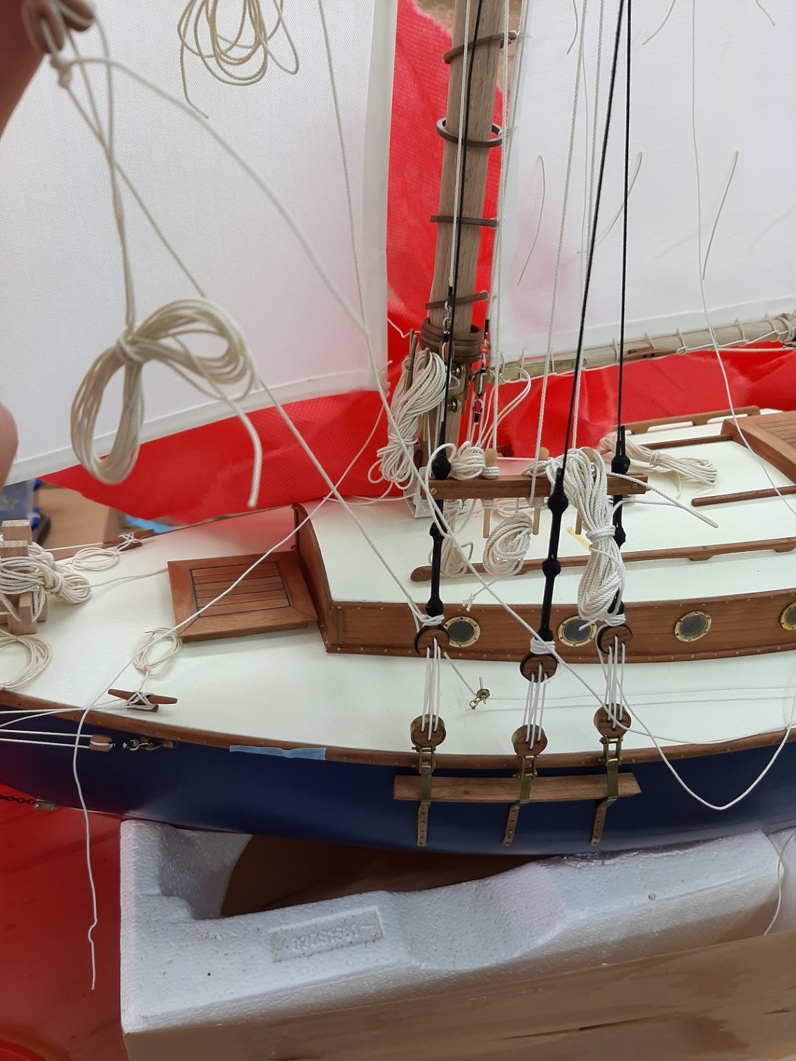
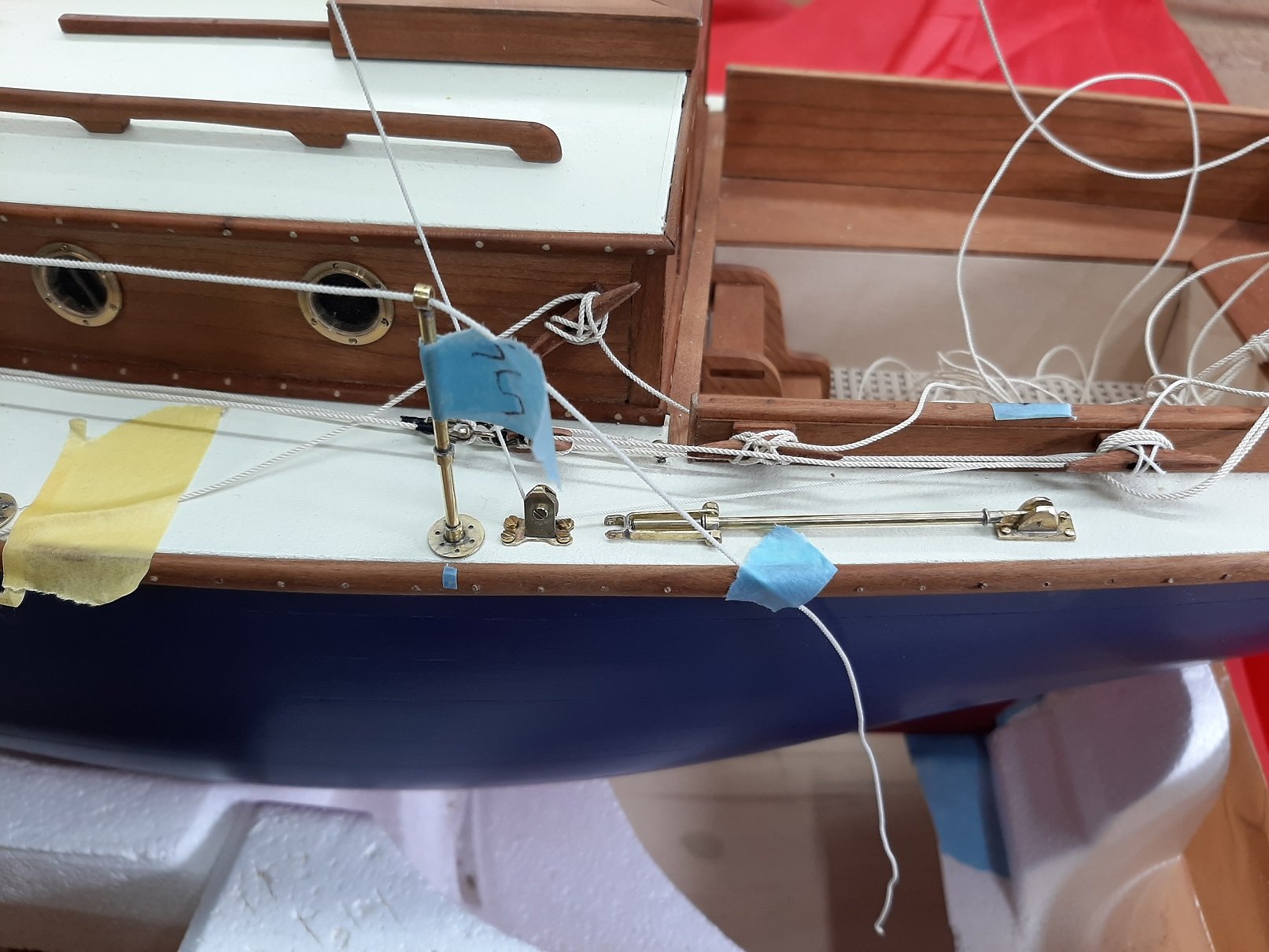
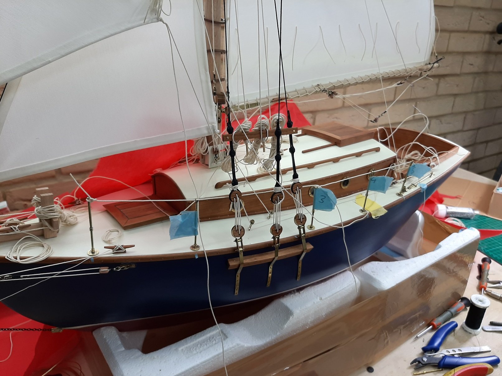
Some pictures
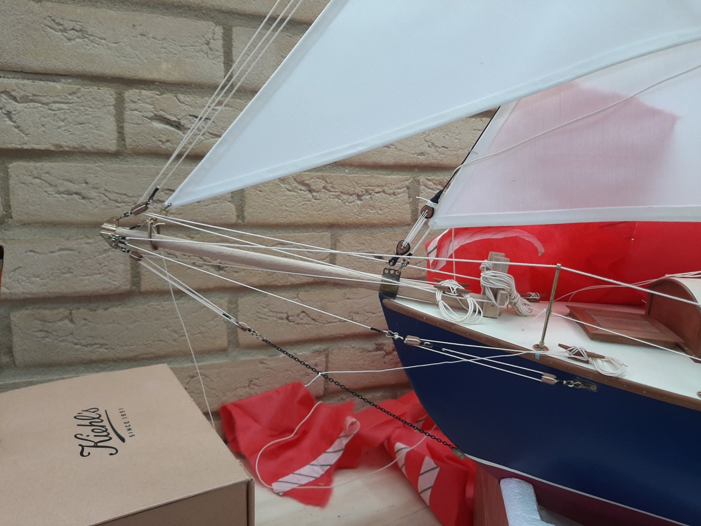
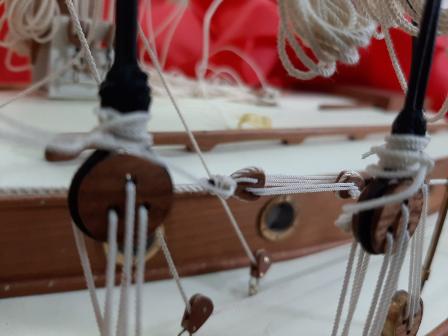
The Highfield lever is clear of any rope.

And with a rope posing as backstay. The wire rope going to the stern is a temporary one

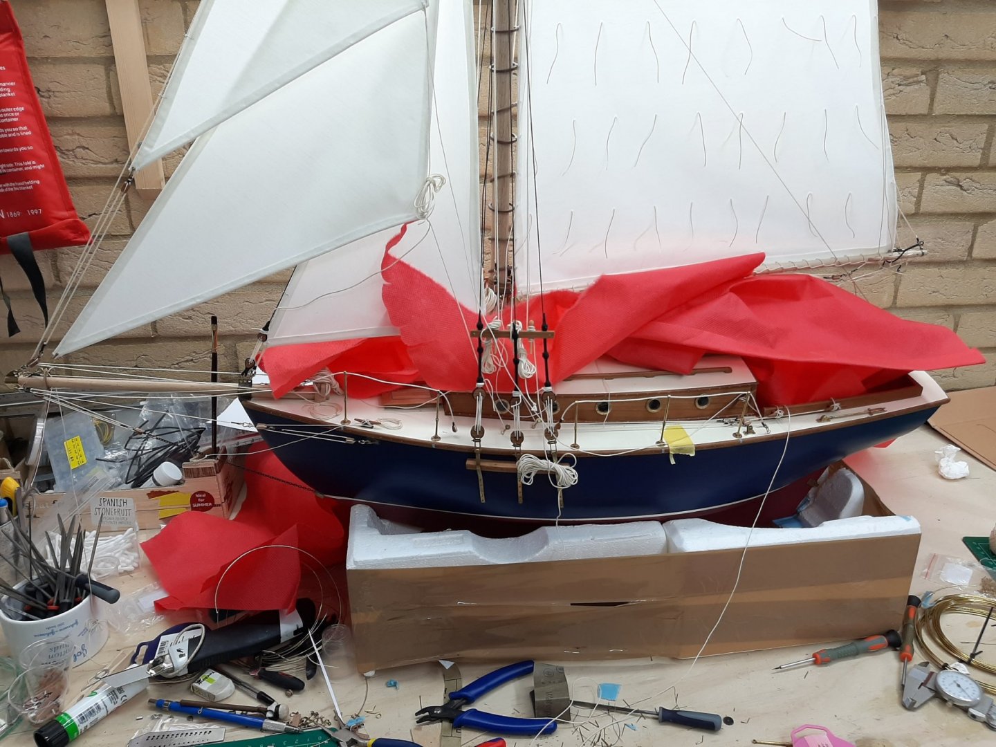
So the port side is done, except for the backstay which will be installed last and of course the main sheet which I am not sure how it will be arranged. Overall however there are many ropes everywhere which is what I was aiming for! The starboard side looks very empty...

Best wishes to all
Vaddoc
-
Very nice work, a very tidy hull! The deck beams will be a ton of work but your 3D work will be a big help.
-
-
Thank you all for your likes and comments.
Moab, a pleasure!
Keith, I have given up on soft solder and have not used my iron for a very longtime. Soft solder is plenty strong but I find silver solder a sharper and cleaner method. I use the small proxon torch. Rarely, due to the large scale I like working at, I have large brass pieces to solder. For these I have a massive torch. It needs a lot of care though as it can easily melt the brass or light up the whole garage!
- KeithAug, Keith Black, michael mott and 1 other
-
4
-
Looks very good Kevin! What is the wood supplied for the deck?
-
7 hours ago, michael mott said:
I'm sure you could add a couple of slabs of wood on either side
😀😀
ok Michael, I gave it another go!
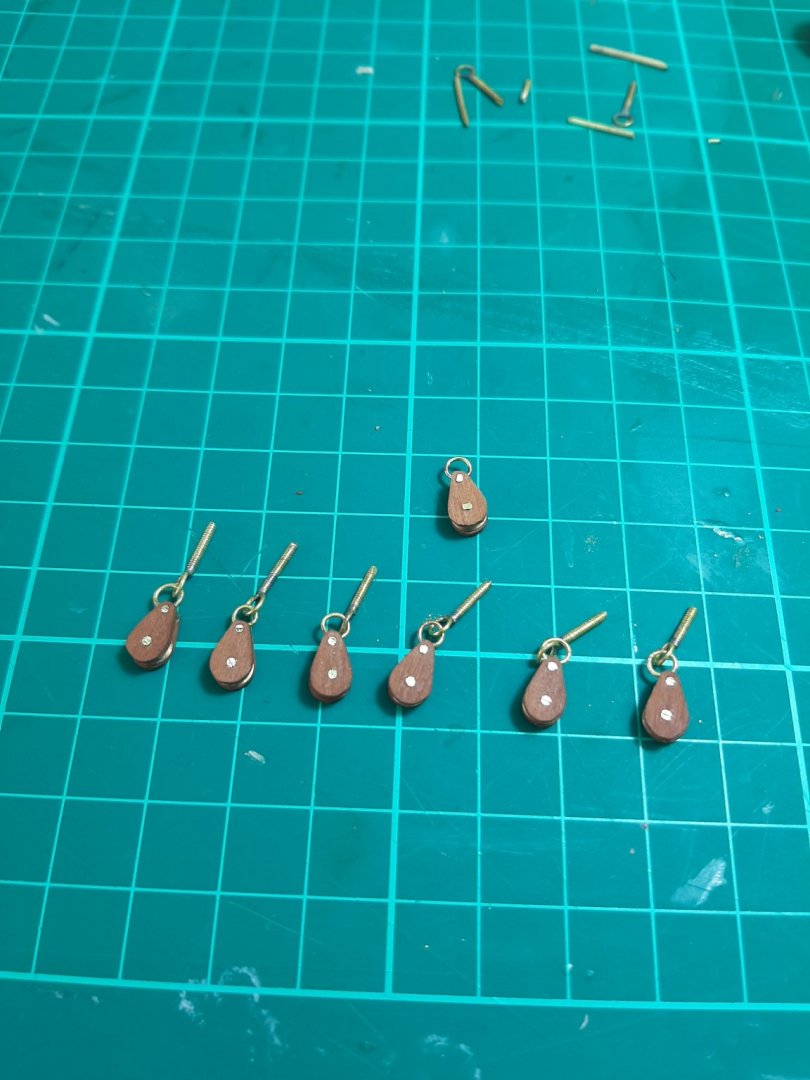
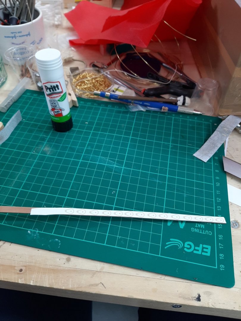
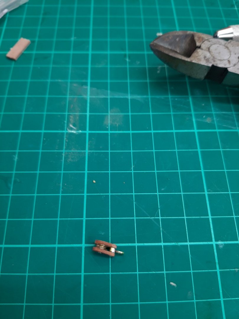
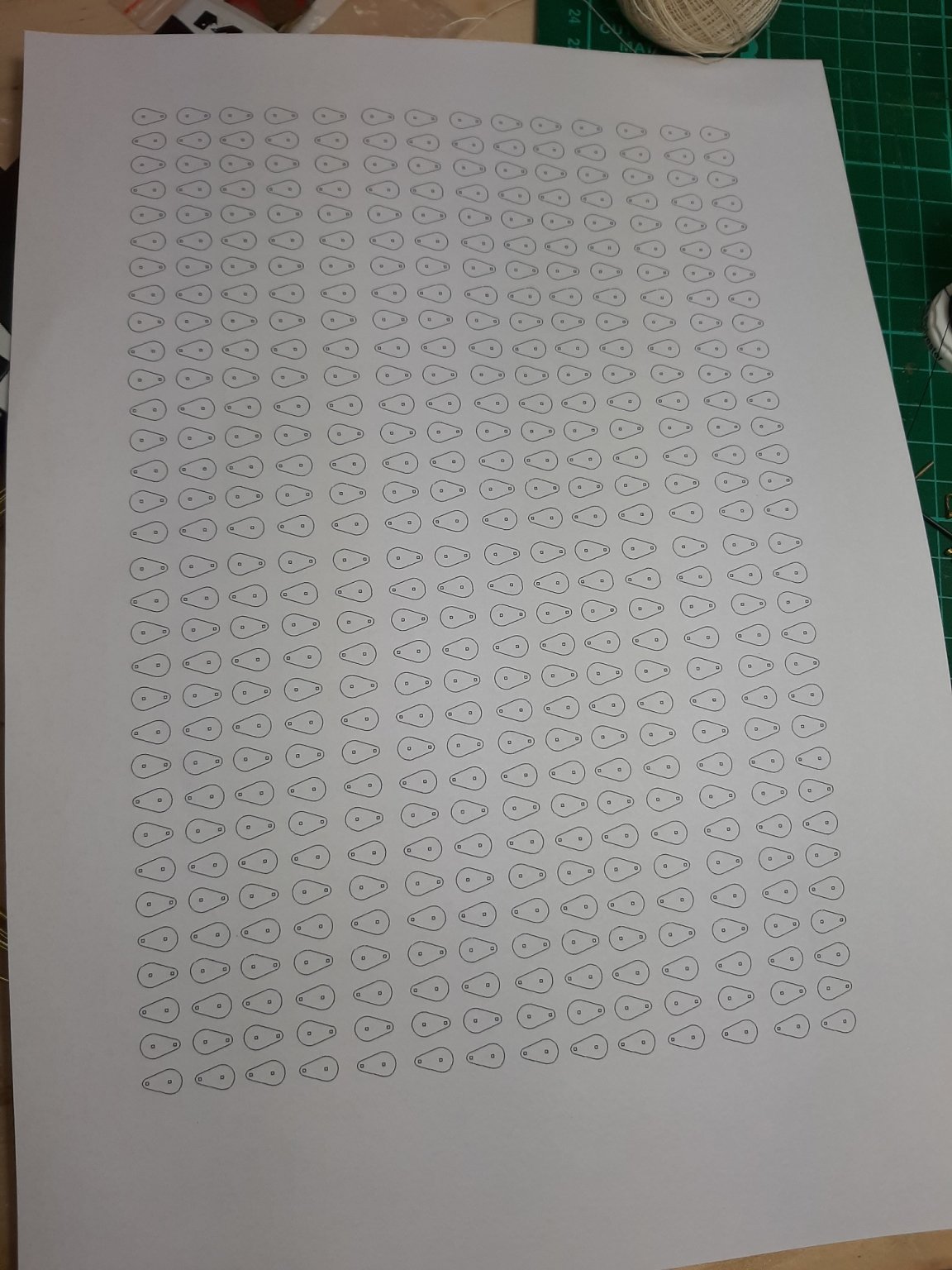
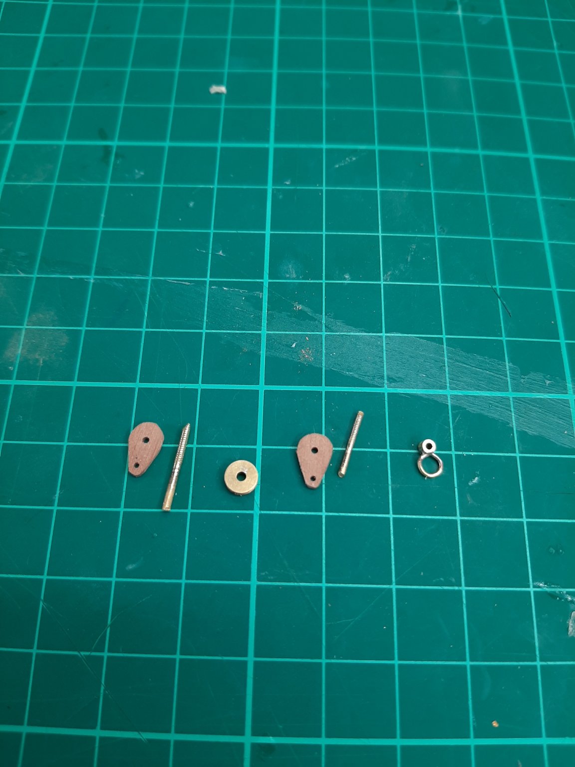
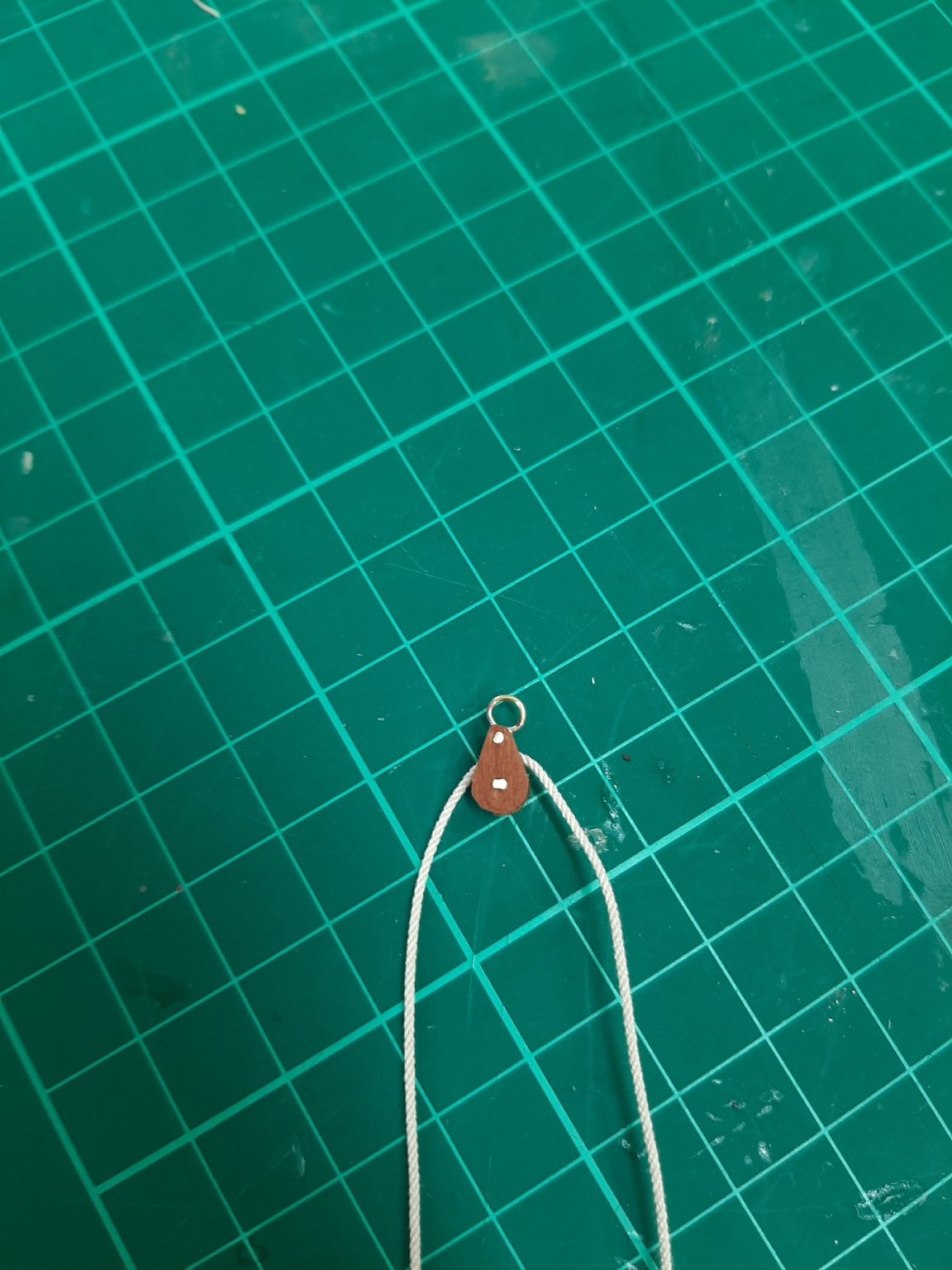
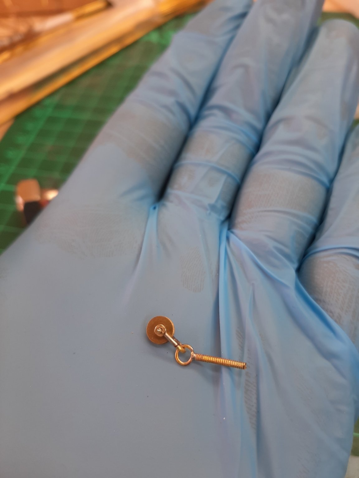
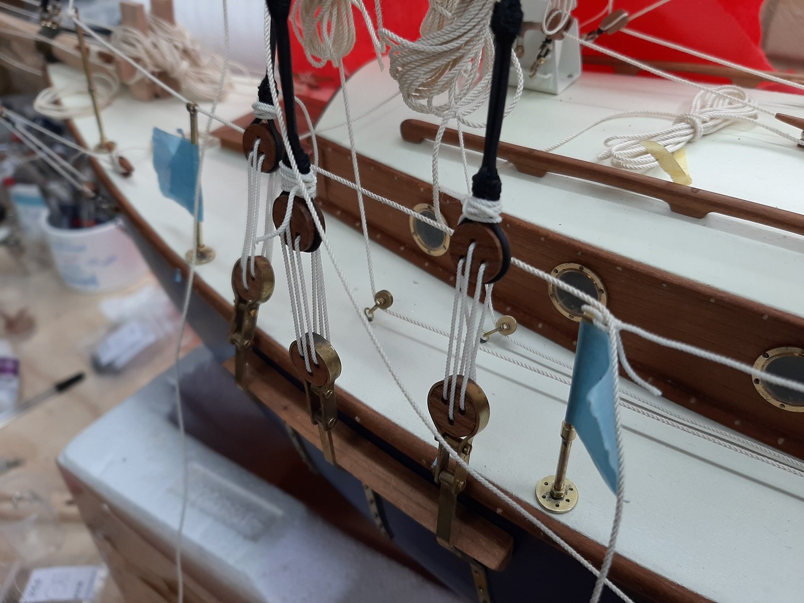
I fired up the computers and quickly designed a roller block for a 5 mm sheave and printed it out on plain paper.

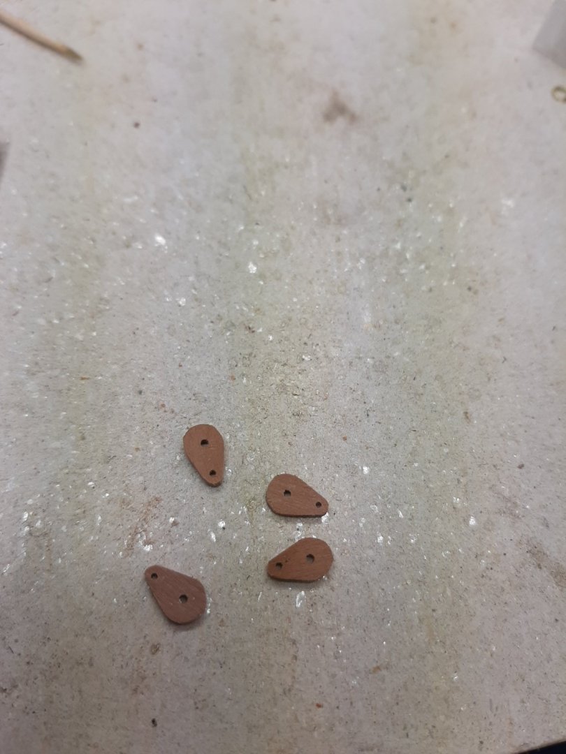
Then, the pattern was glued to a strip of wood, I think cherry, 1 mm or so
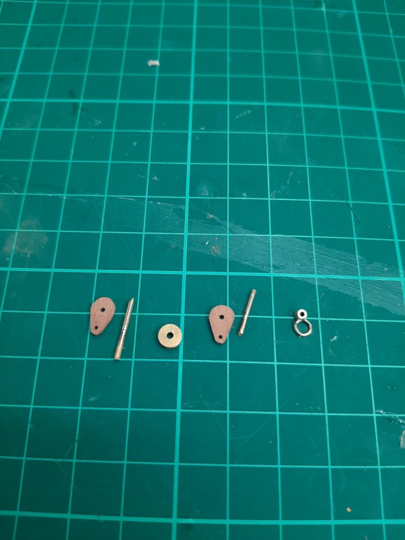
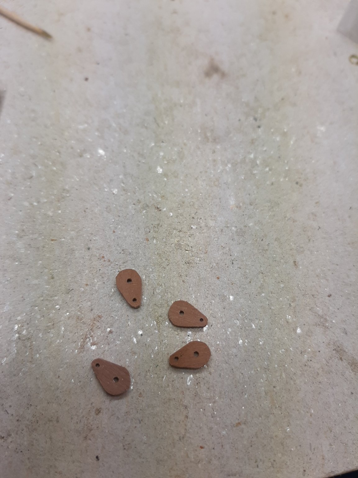
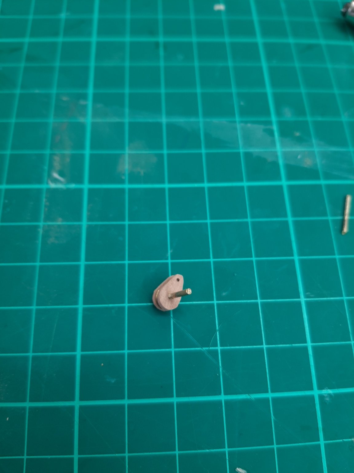
The pieces were drilled with 0.9 mm drill for the 1 mm axle and 1.1 mm drill fro the 1.2 mm axle and the outline roughly cut
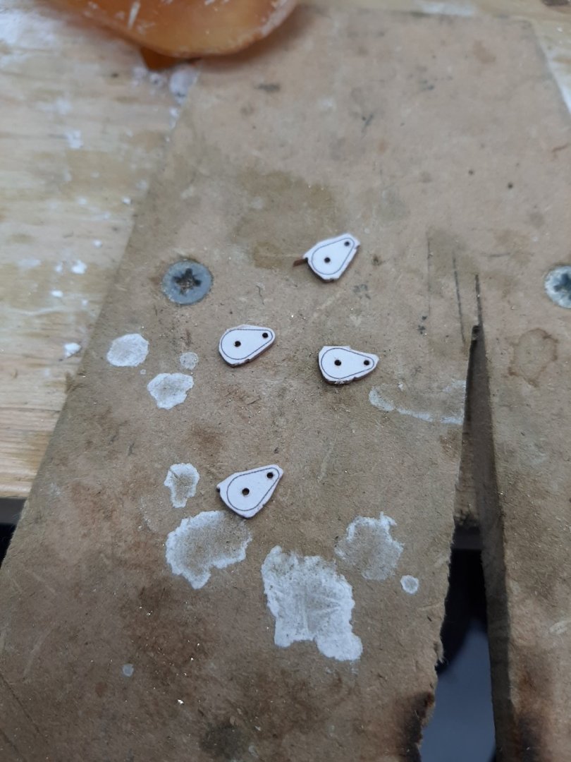
Then they were sanded carefully
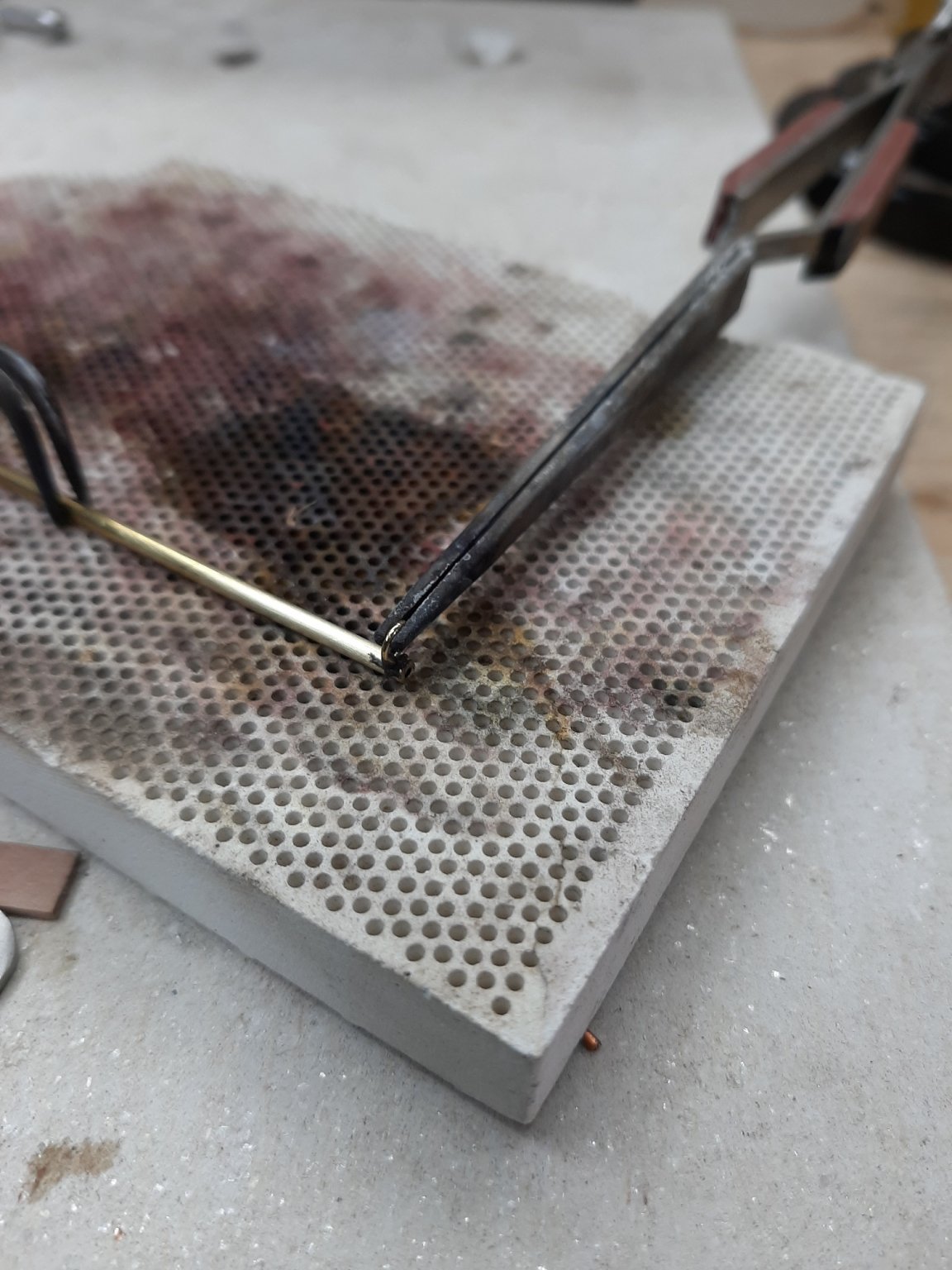
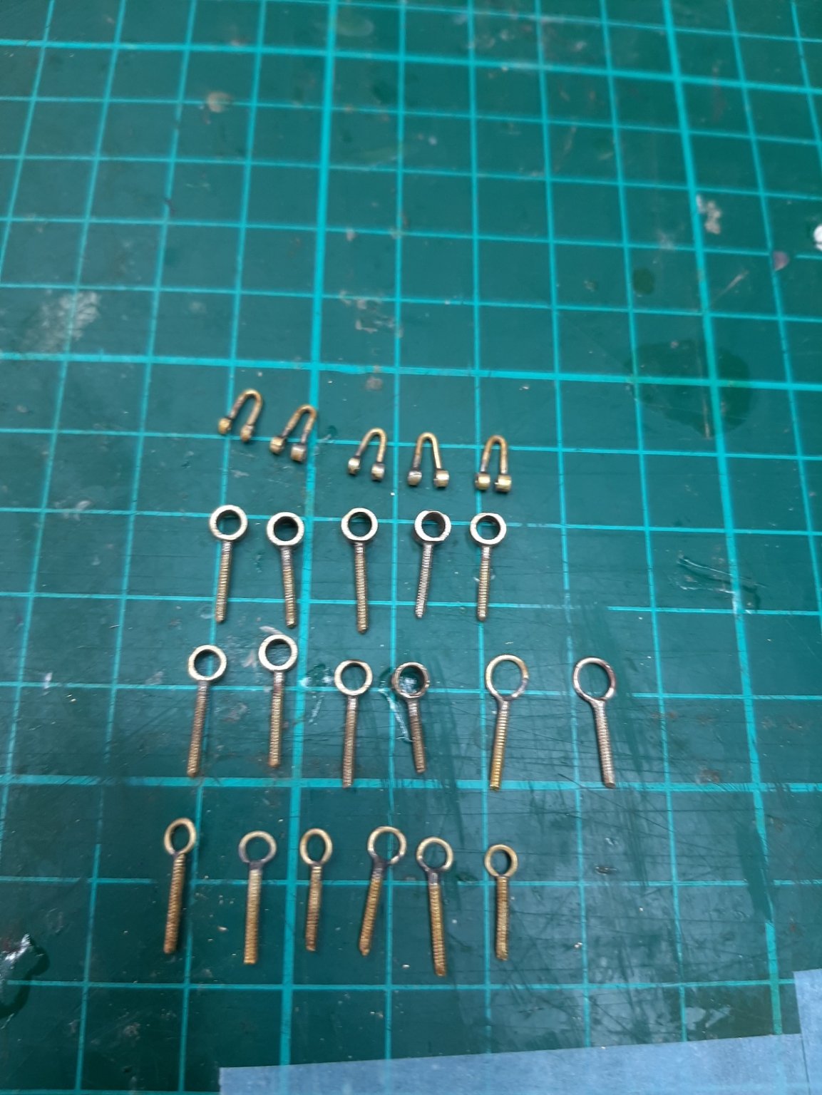
The axles were anealed, straightened and threaded.
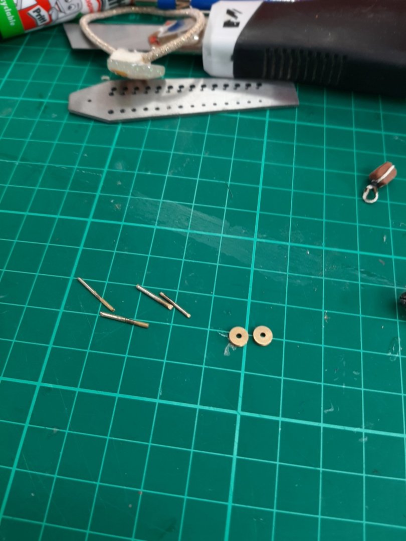
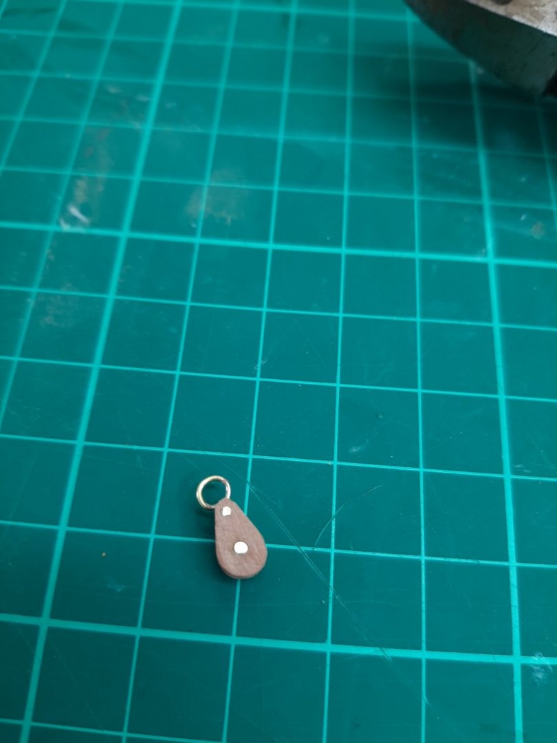
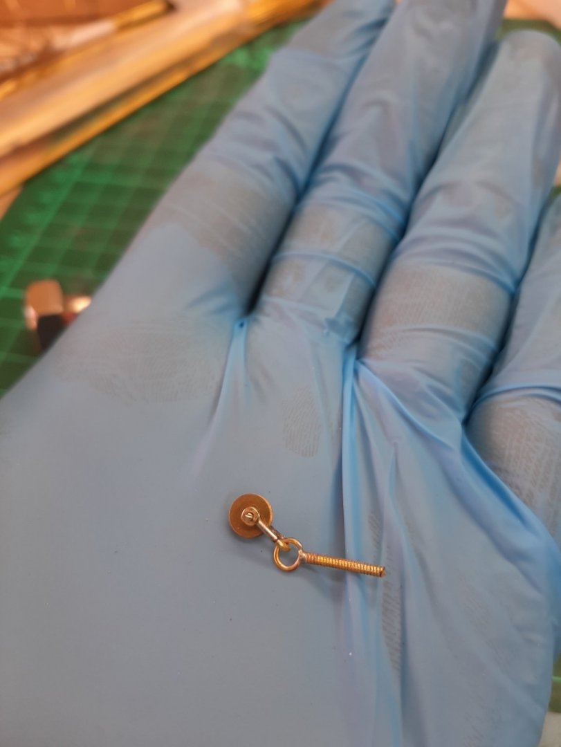
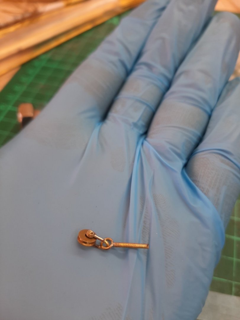
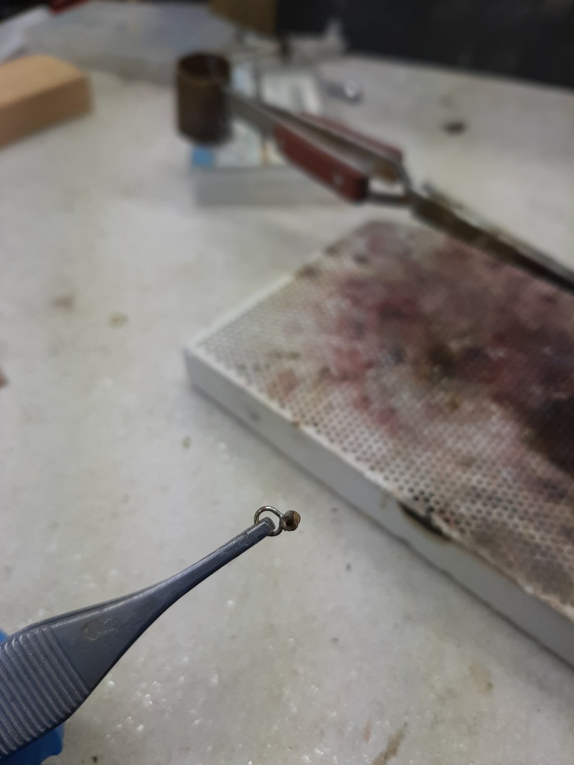
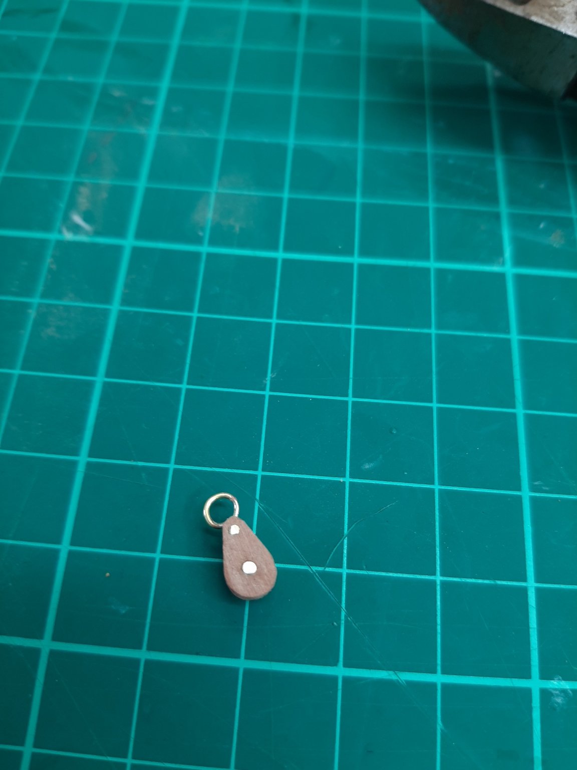
an eye was silver soldered to a 2 mm brass tube

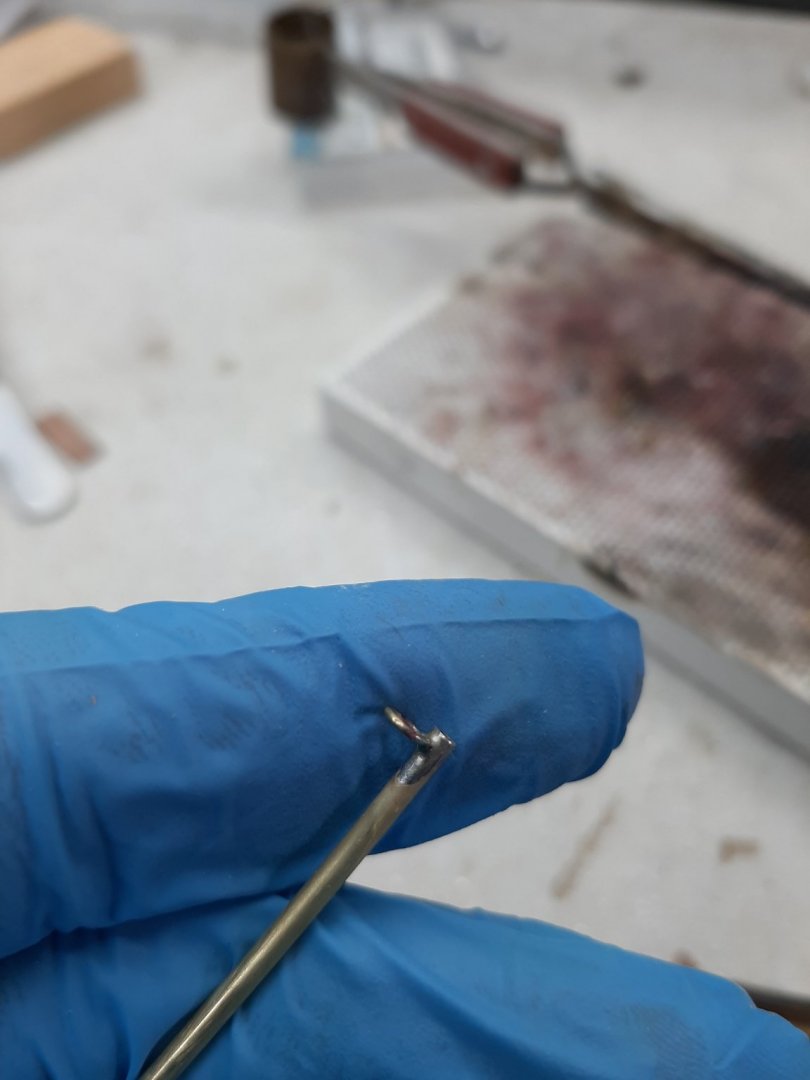
then the tube was shaped and cut to the thickness of the sheave

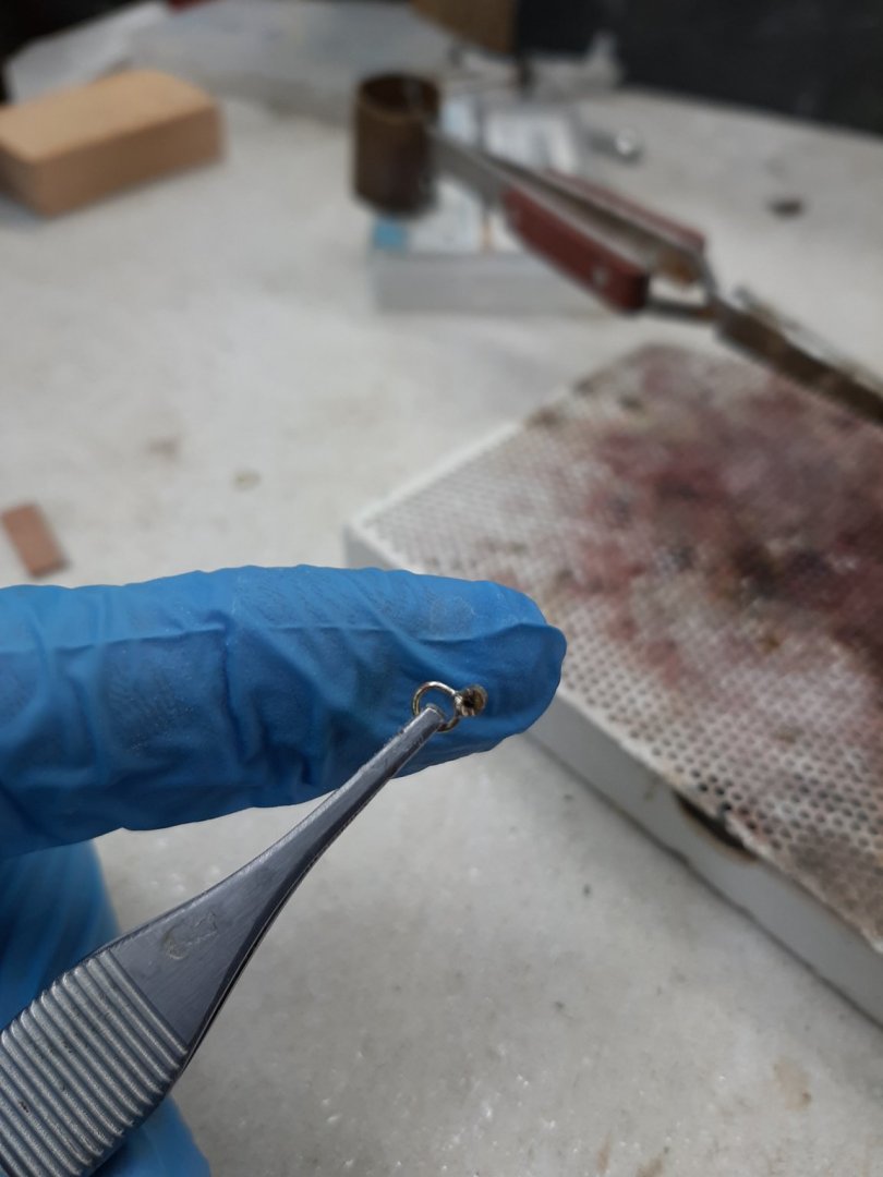
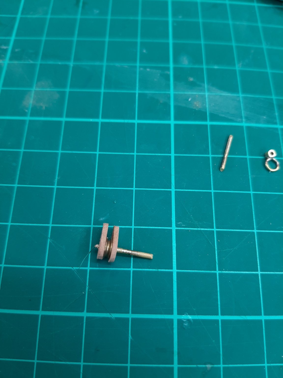
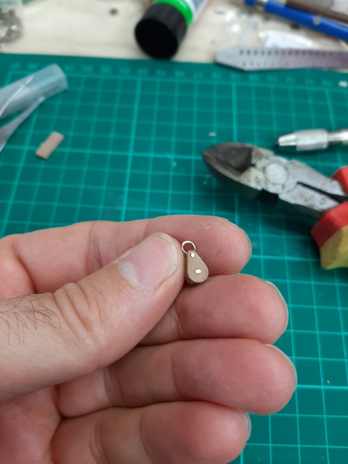
All the components ready for assembly
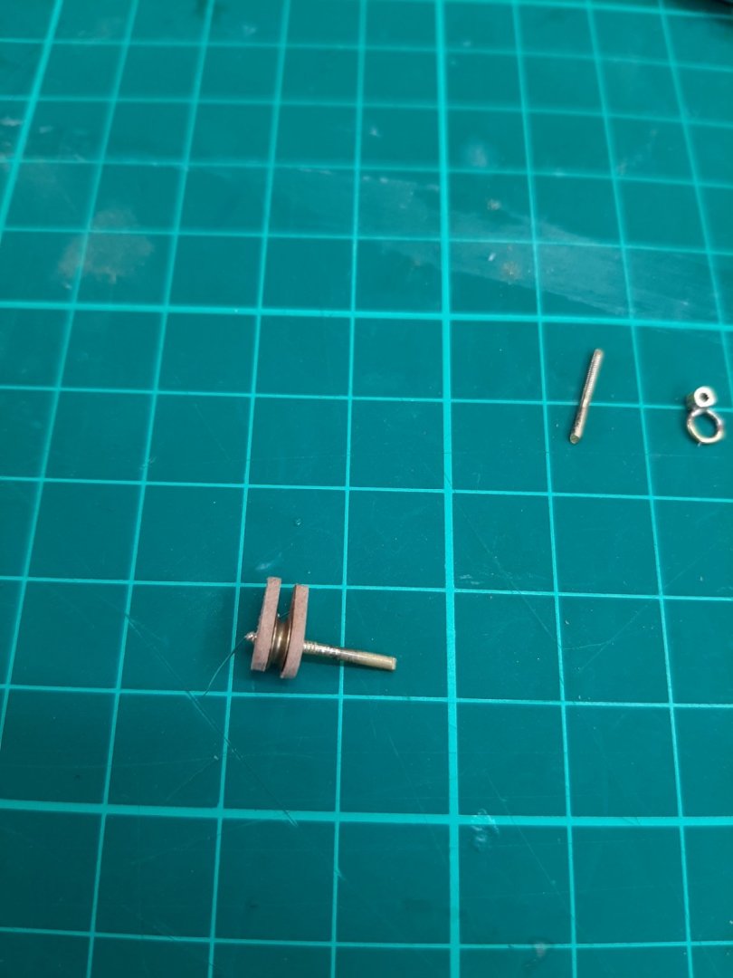
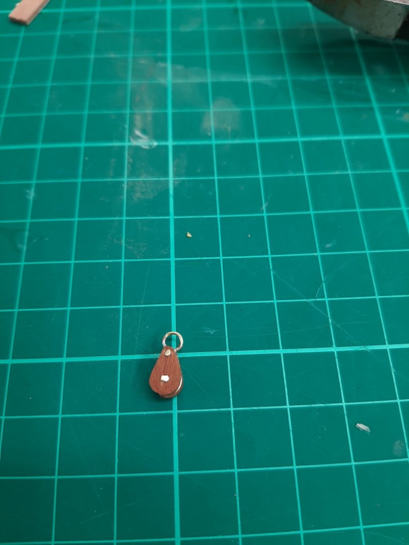
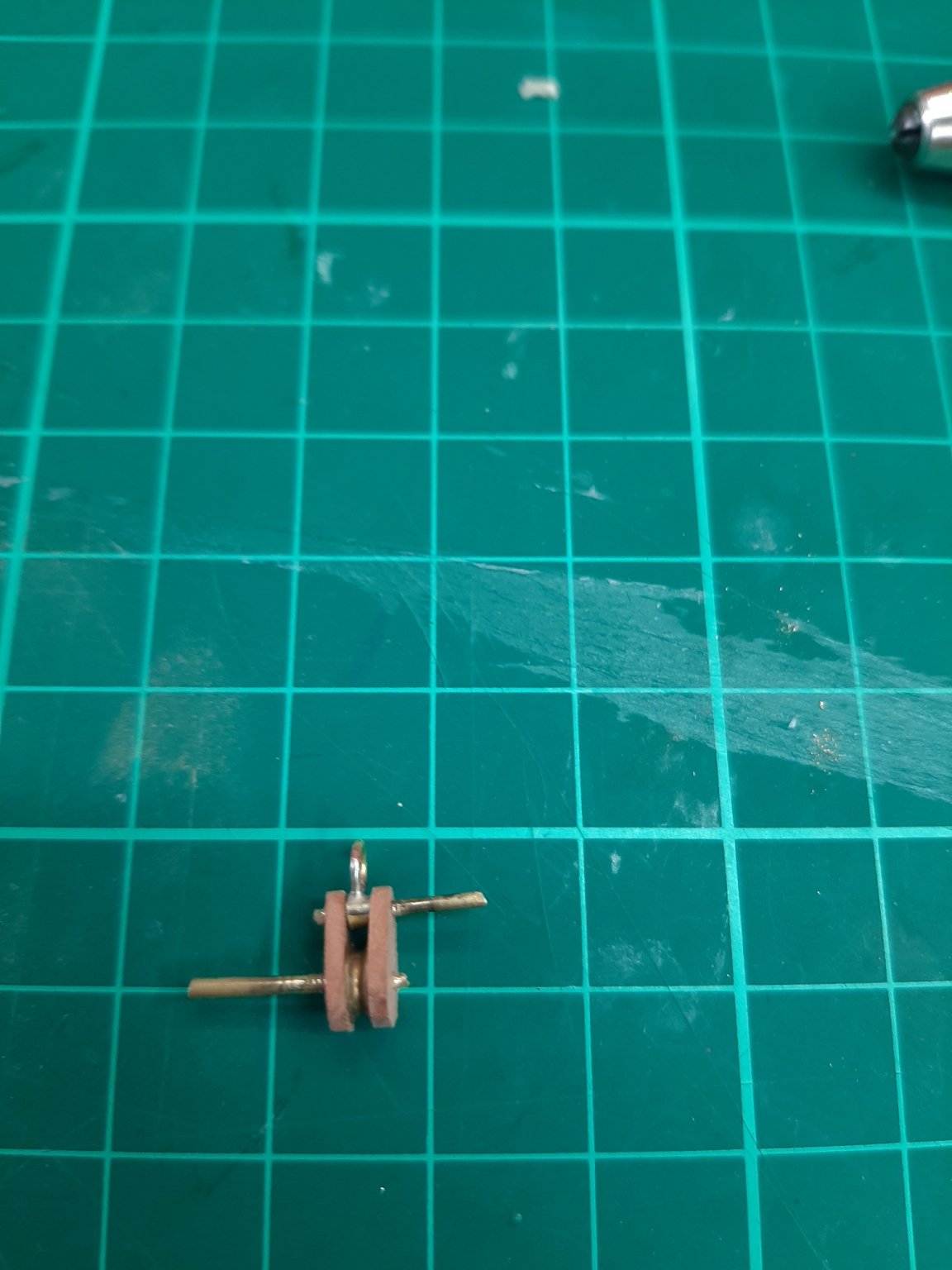
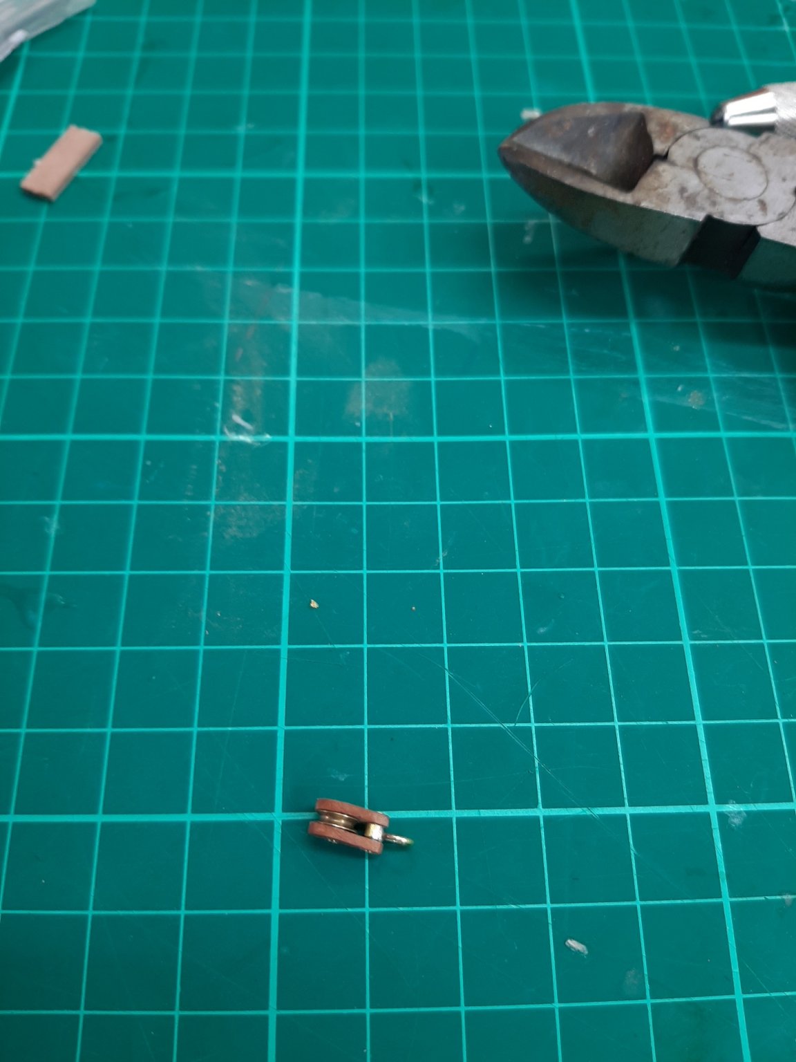
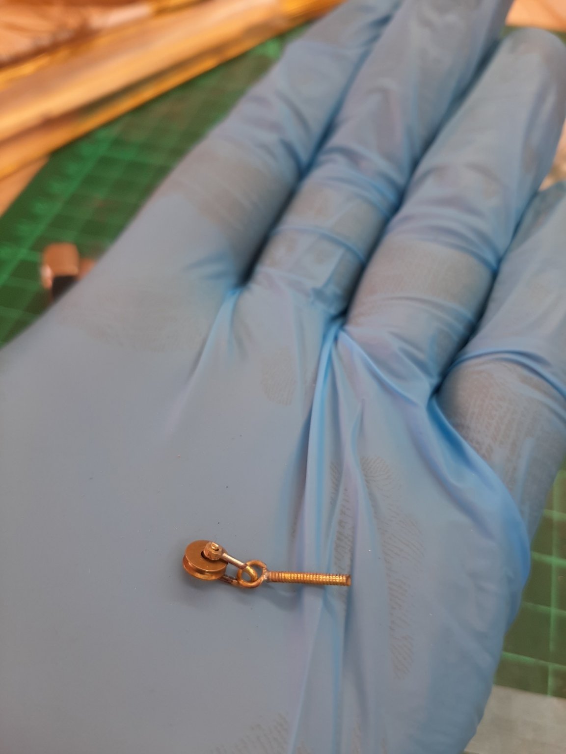
The sheave axle went in first, then the top end assembled and the ends trimmed and sanded flush.

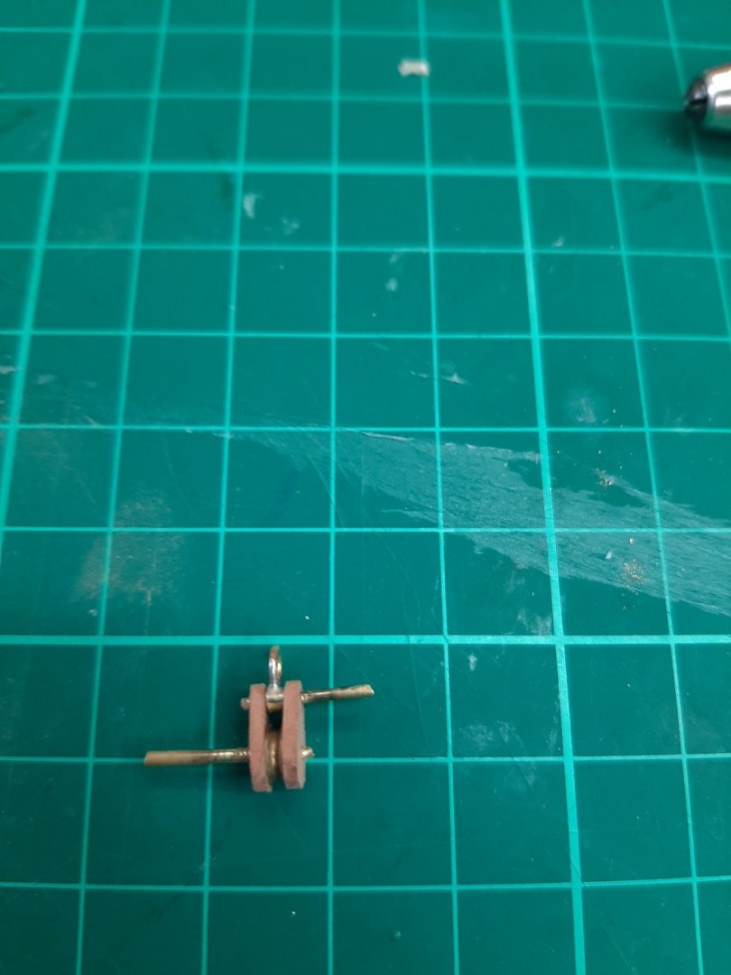

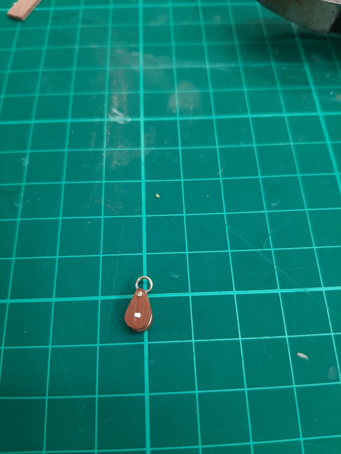
And came to life with Tung oil
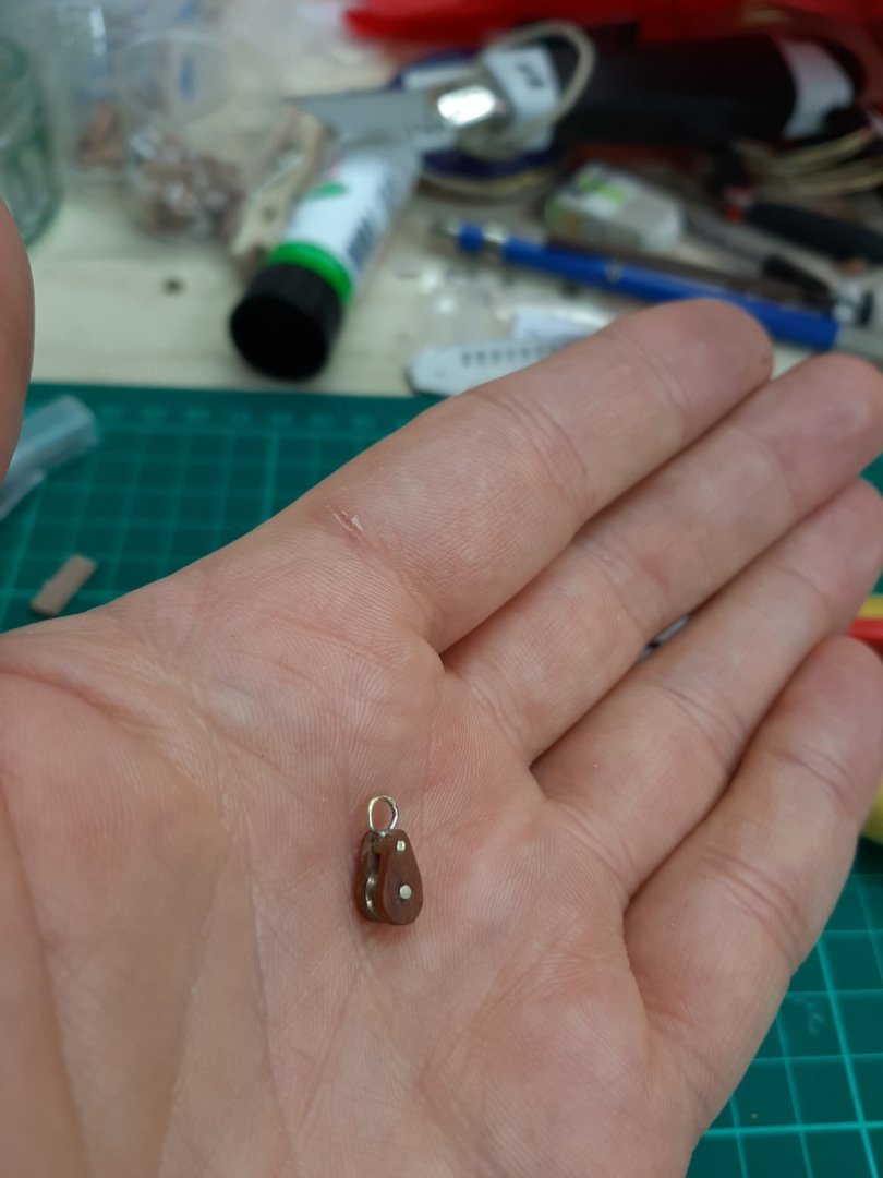

I think that indeed it looks much better! The eye actually pivots and it works very smoothly. Many thanks Michael!
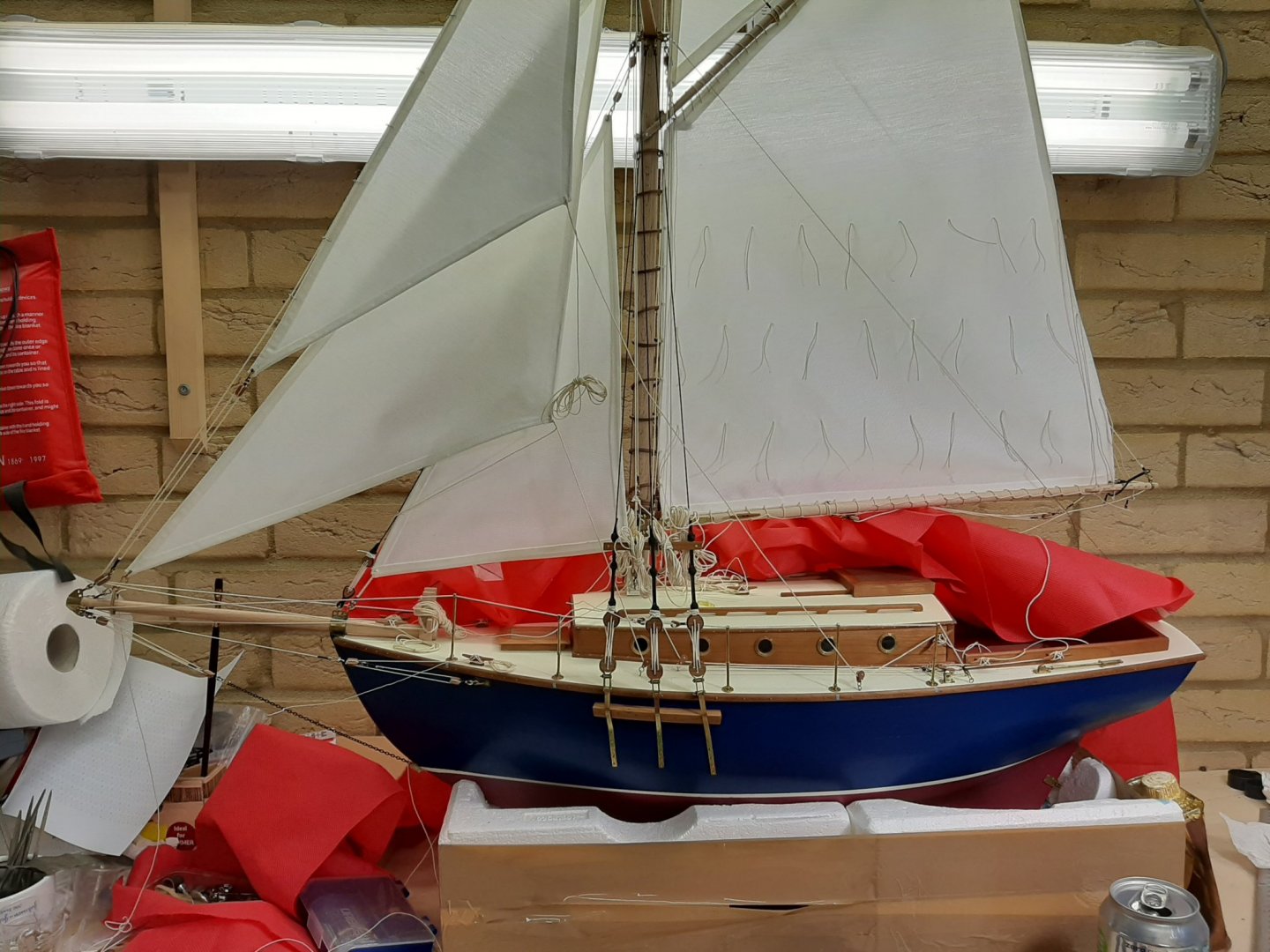
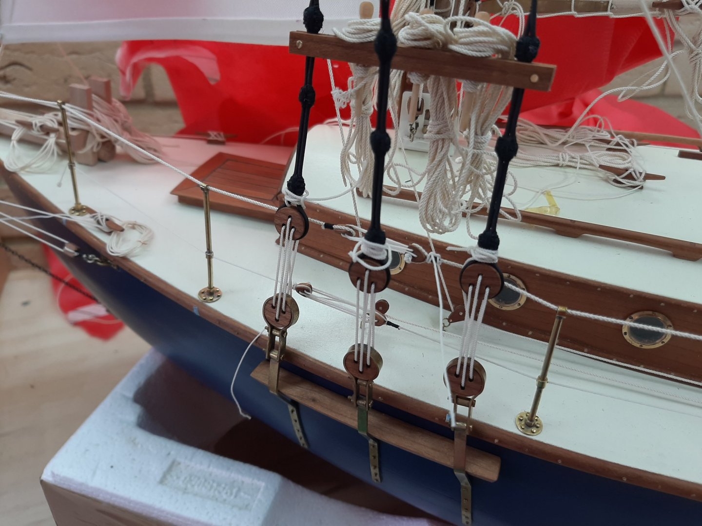
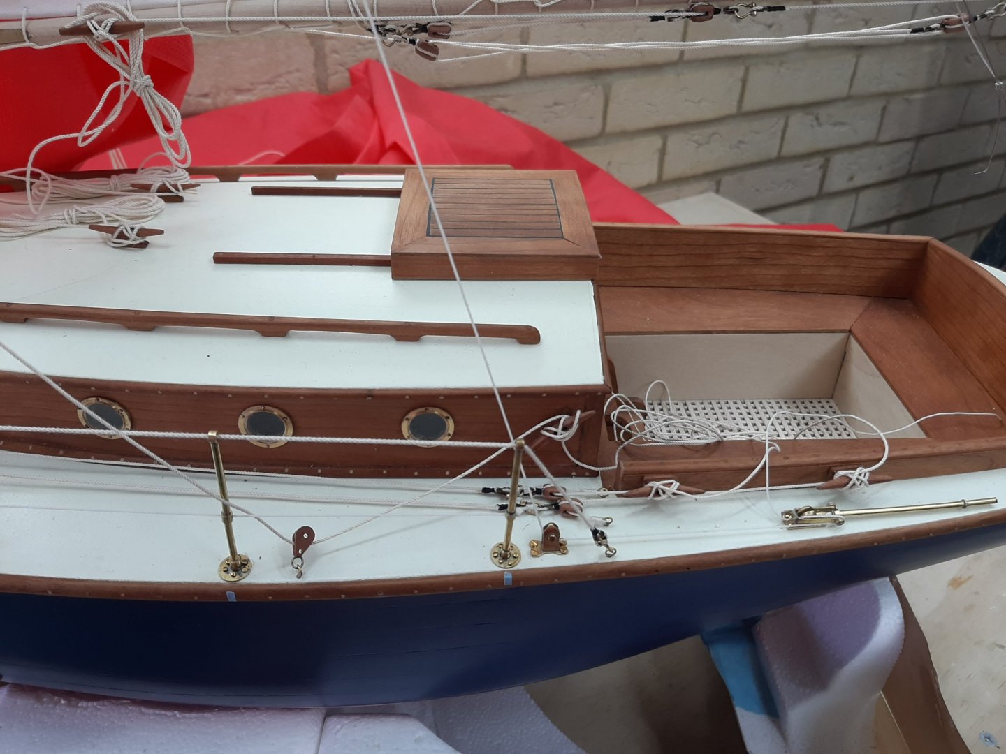
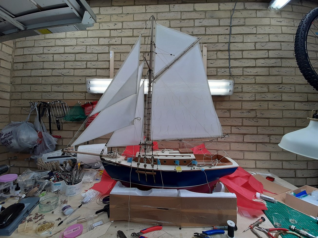
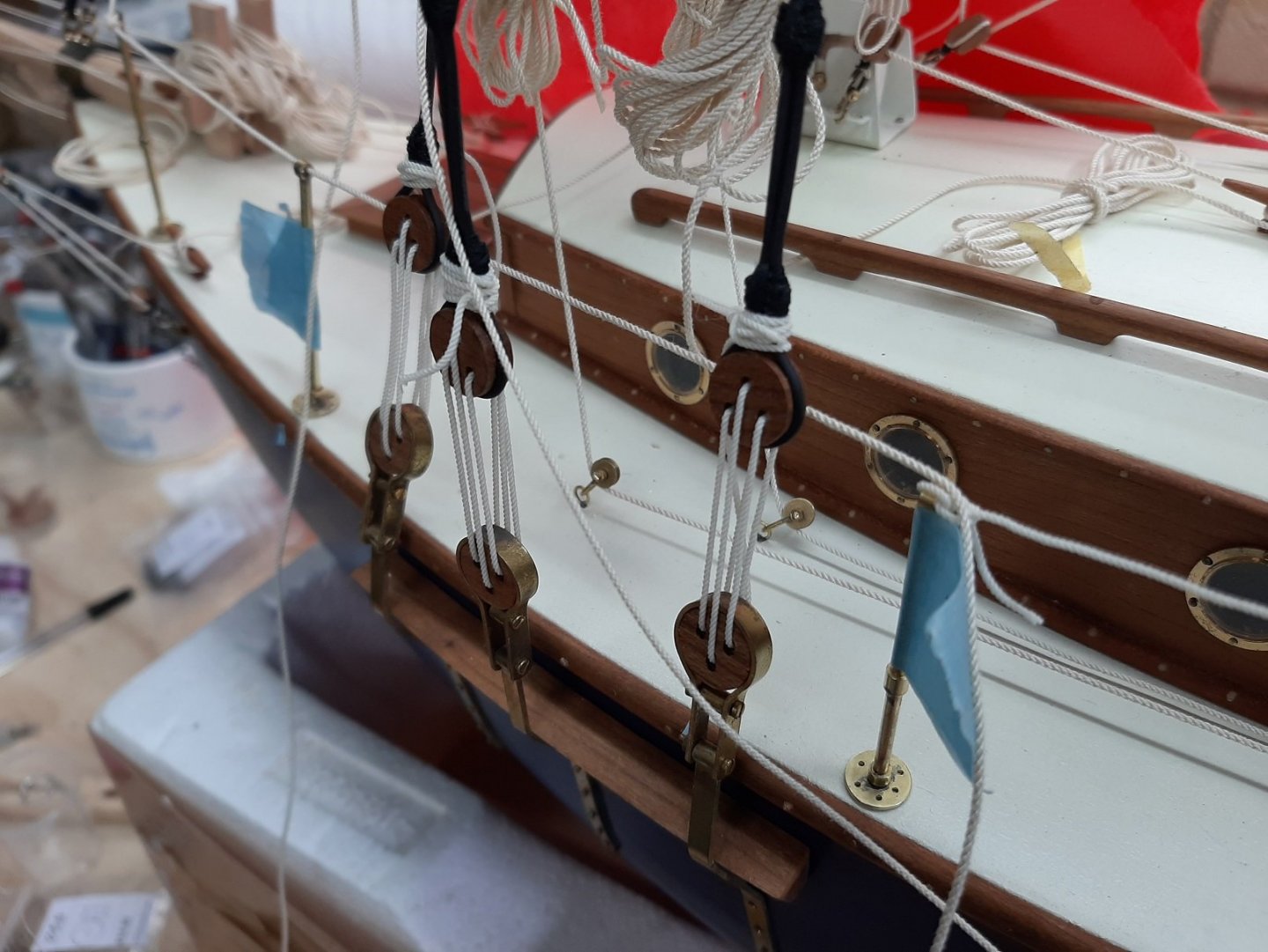
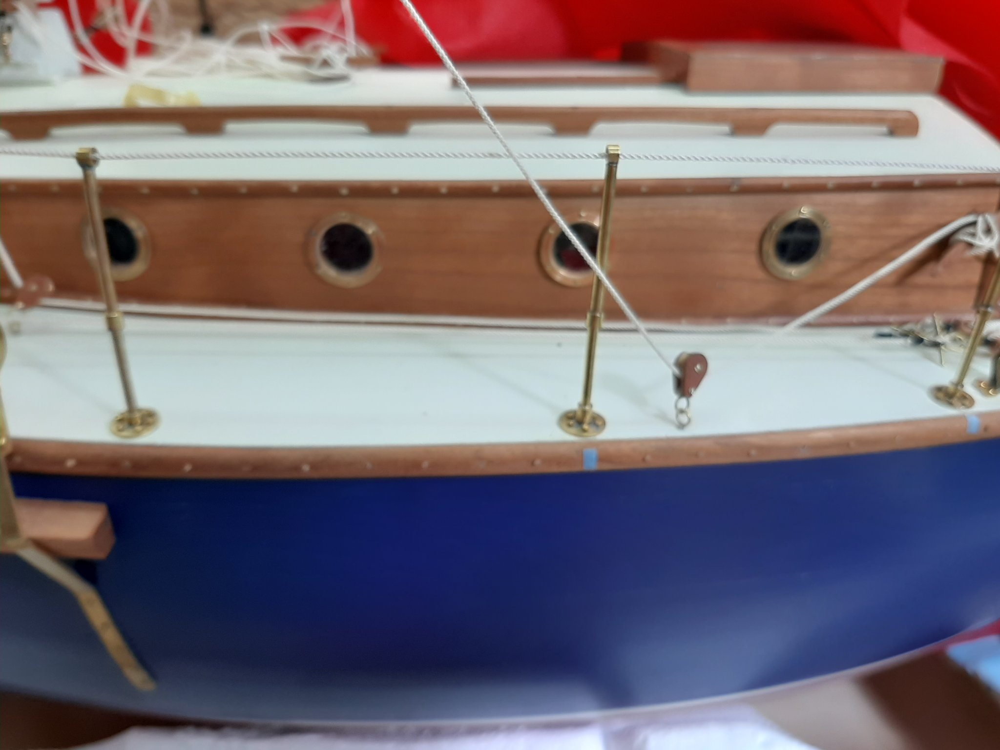
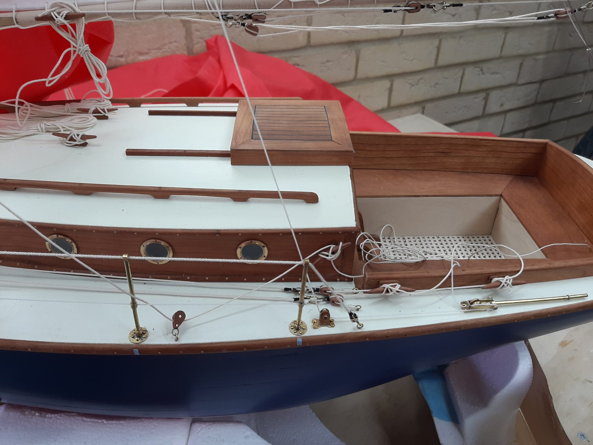
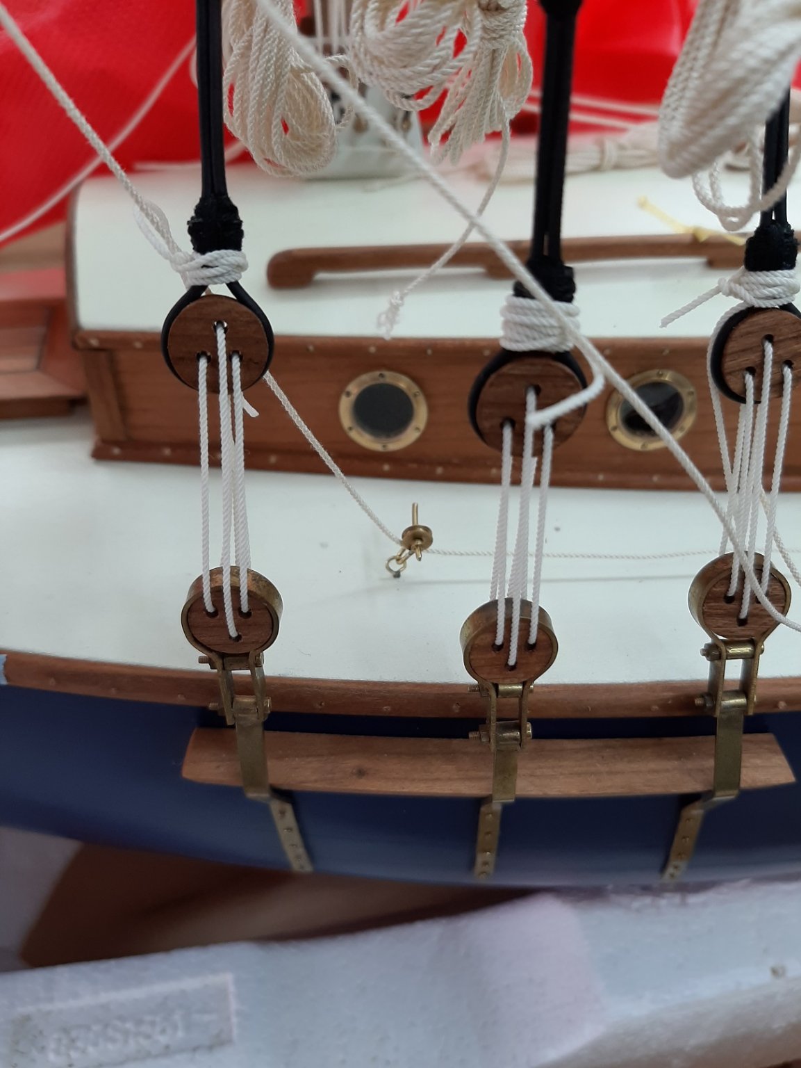
I also installed the poles for the rails. It took a bit of work to drill and aline everything and I did not use any glue, only brass pins cut and the tip reformed. They are super solid.


I then installed the upper rope, one end shackled to the bowsprit, the other to an eye at the deck. I have also prepared two hearts for the middle to tension the rope. The red cloth is there to protect the boat from the dust in the garage.
This is a great forum, many thanks to all for your likes, your valuable advice and encouragement.
Regards
Vaddoc
- FriedClams, MEDDO, Colin B and 12 others
-
15
-
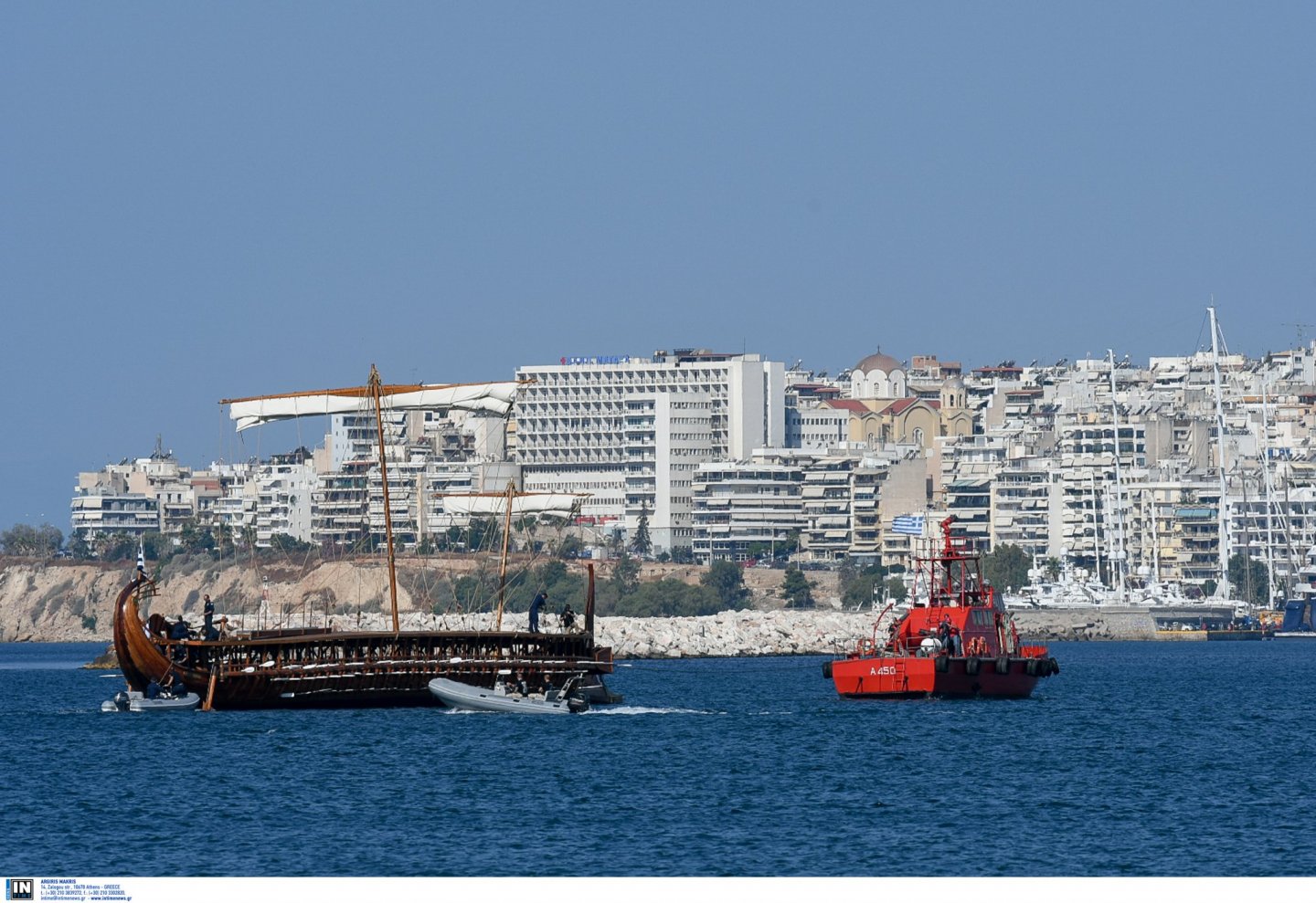
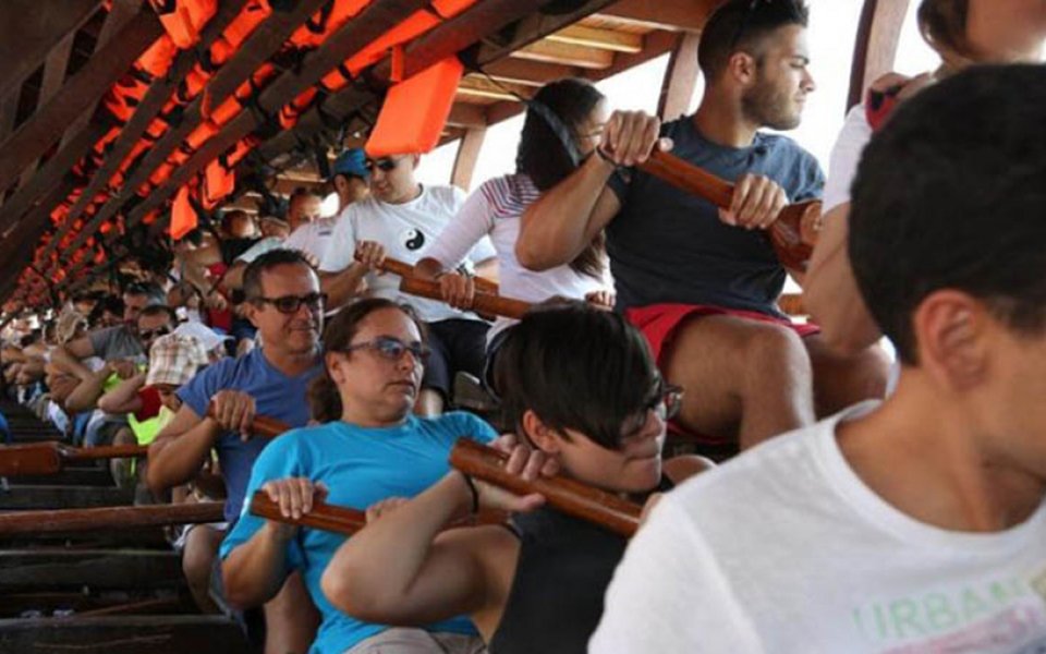
Richard, this is a very nice ship! Very clean and tidy work.
Olympias is actually open to the public to visit, travel and row! I think they only use the two upper rows in these journeys.
- popash42, mikegr, flying_dutchman2 and 2 others
-
5
-
-
The hull looks better with every post. Looking forward for the next chapter.
-
-
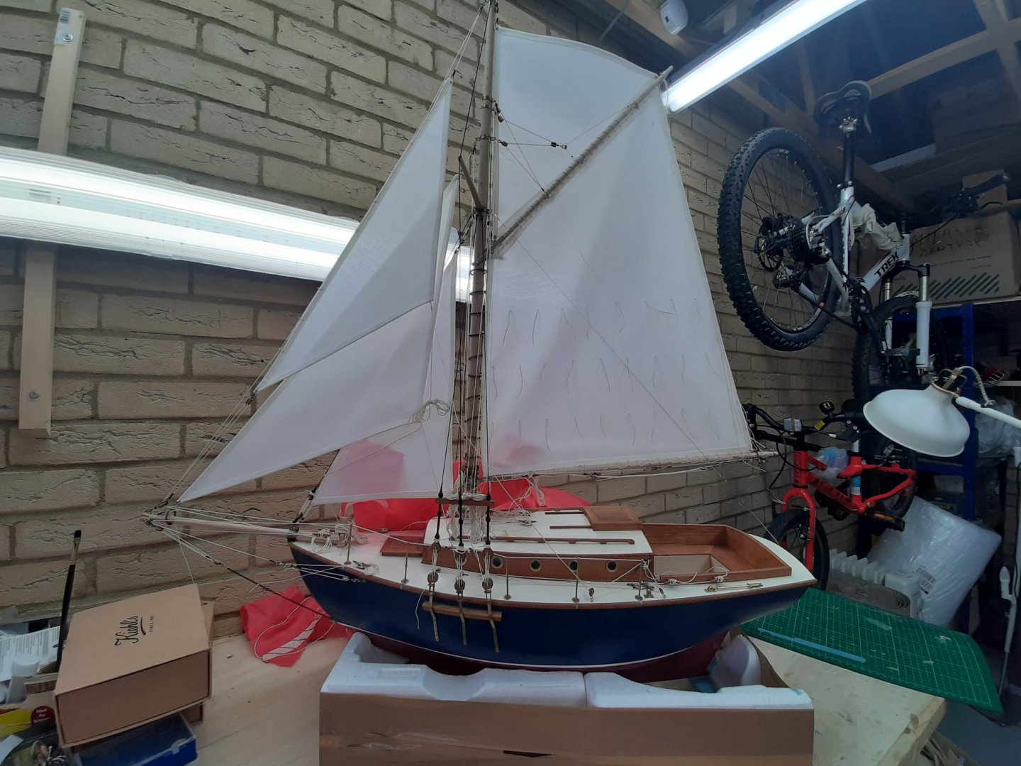
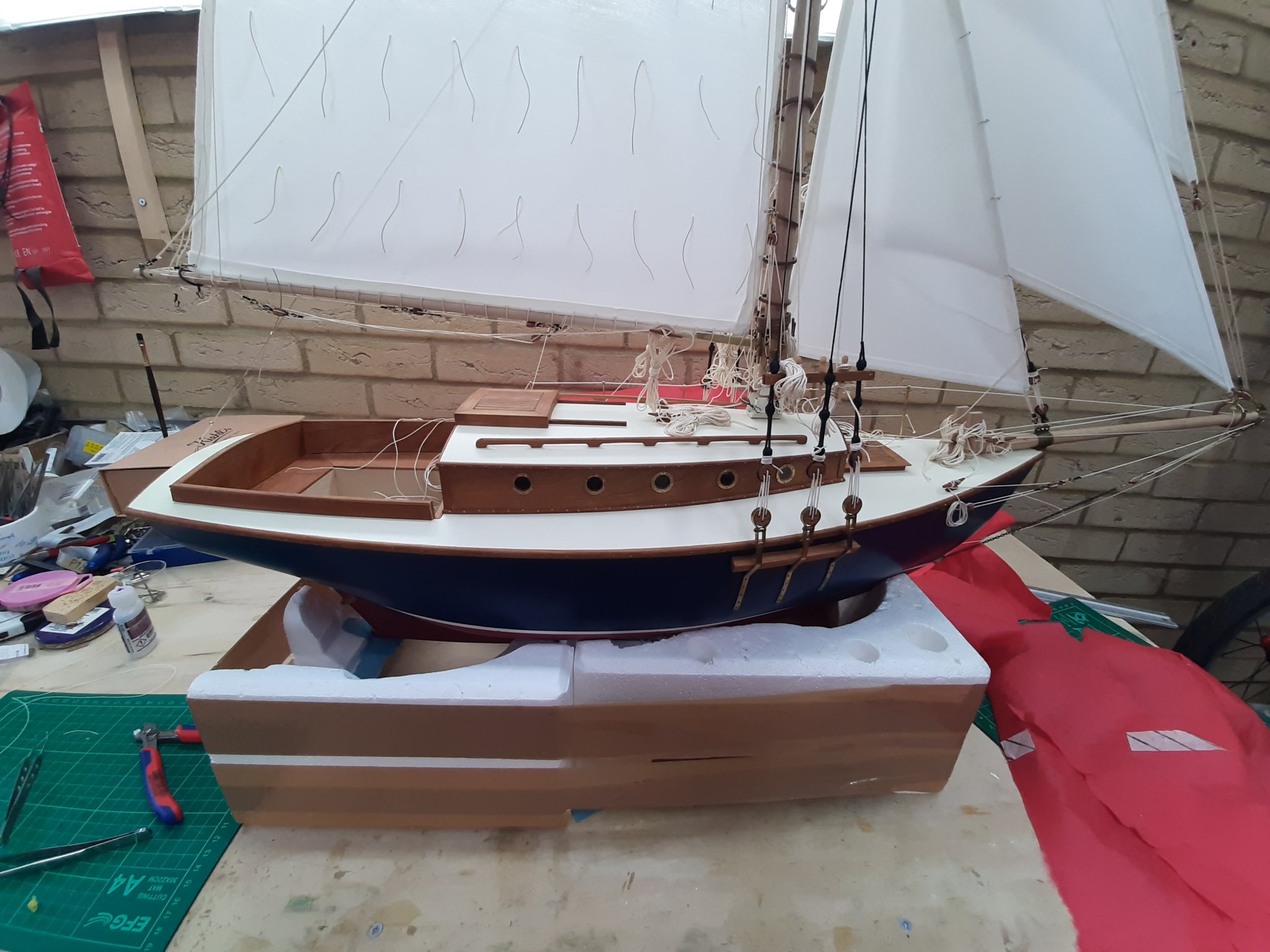
Proper progress today so time for another post!
Today was a frightening day. I drilled many massive holes on my deck, no room for failure, no turning back.
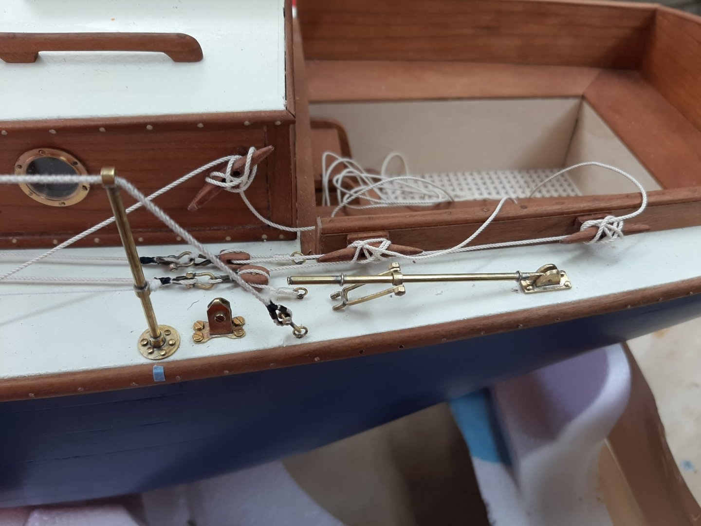
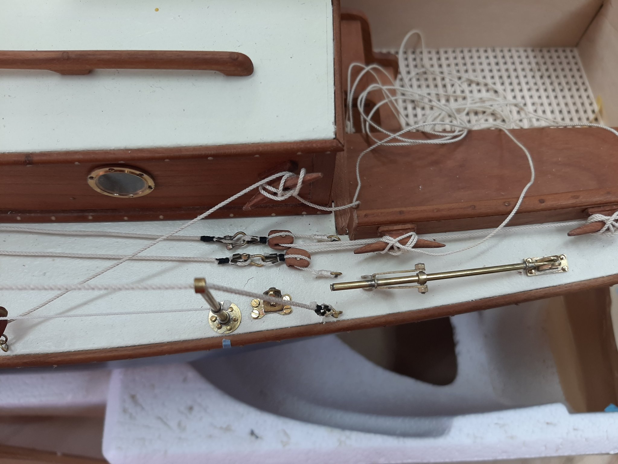
First of all, I made a number of deck fittings to tie and route lines. I ve been using a lot my new tap and die set so all fittings will be screwed and not glued. I also finally manage to sort out my pickling solution, I had forgotten that hydrogen peroxide is needed so all my brass pieces were coming out pink

Now despite using only blocks and not winches, the Deben is a contemporary boat and a really small one. So I thought that some kind of roller/metal sheave would be used for the jib sheets. So I made a few that actually work surprisingly well. Of course, if I change my mind I can simply unscrew and use blocks. I tried a few other designs but unfortunately this is the limit of my metal work.
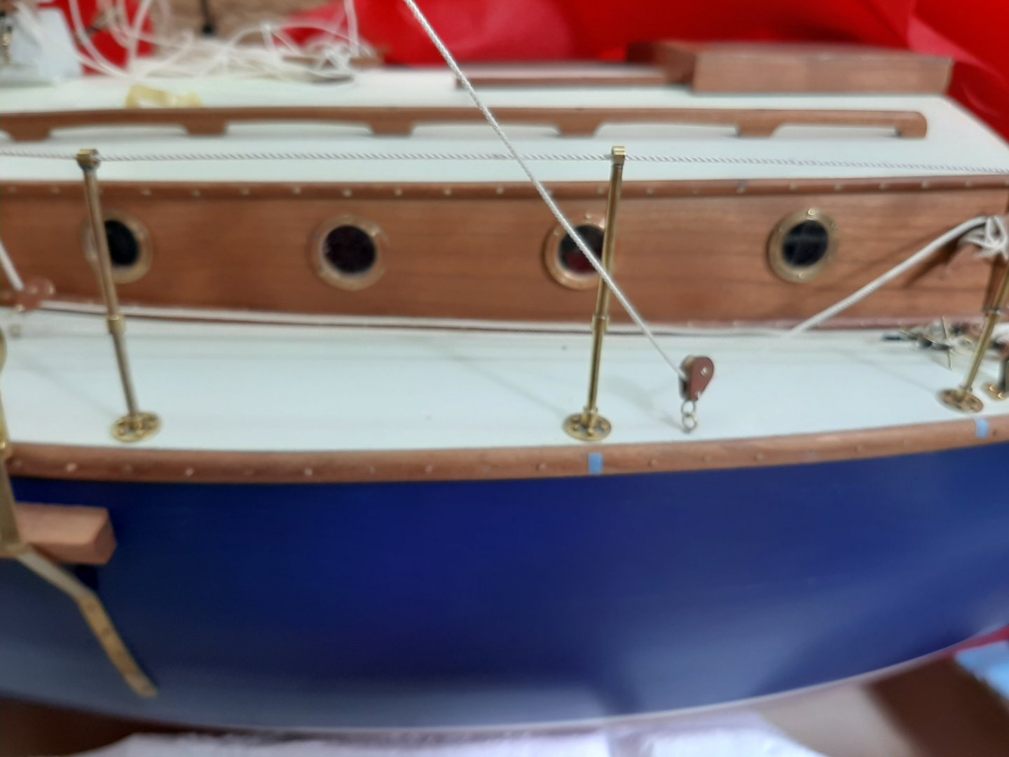
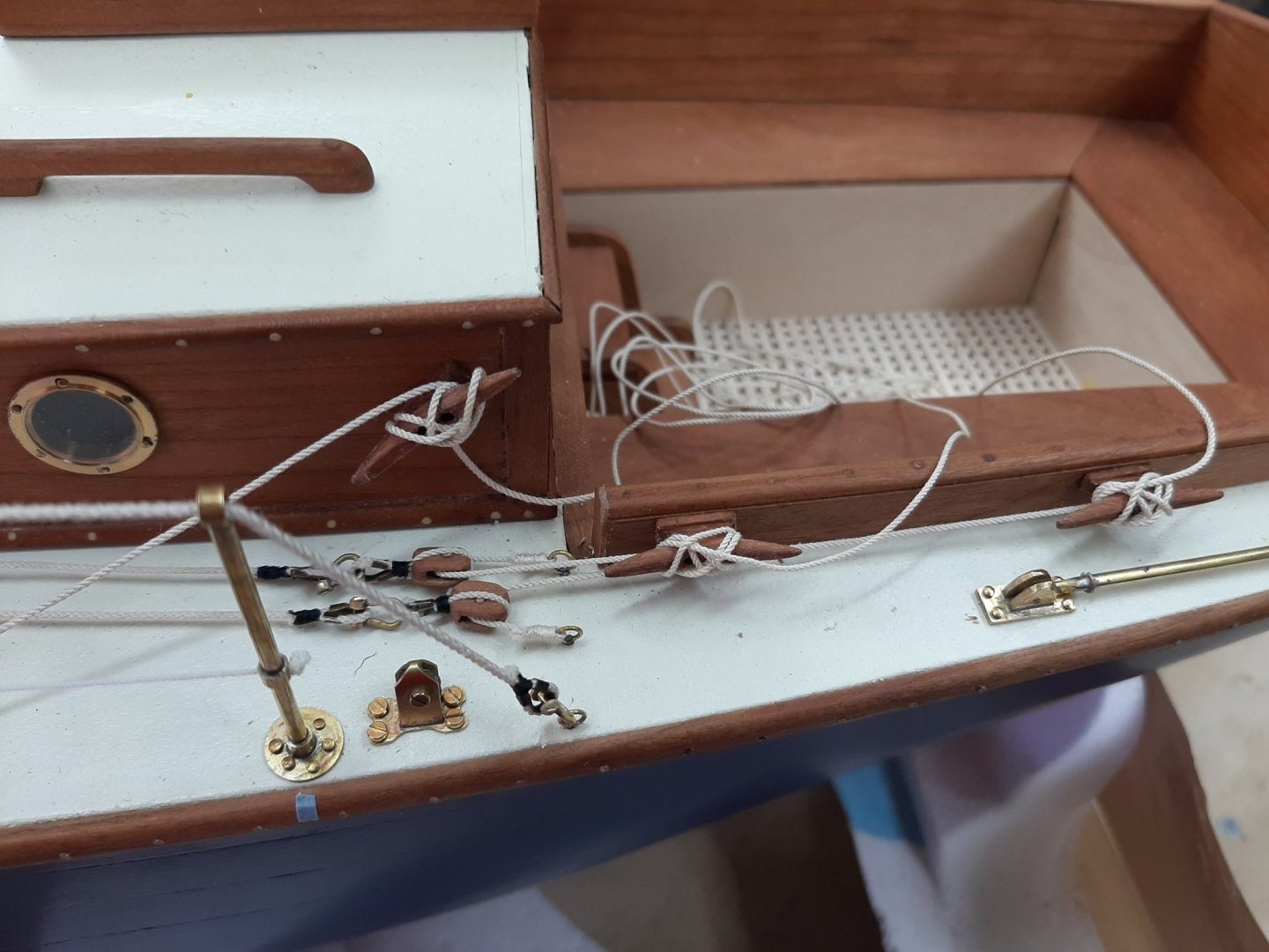
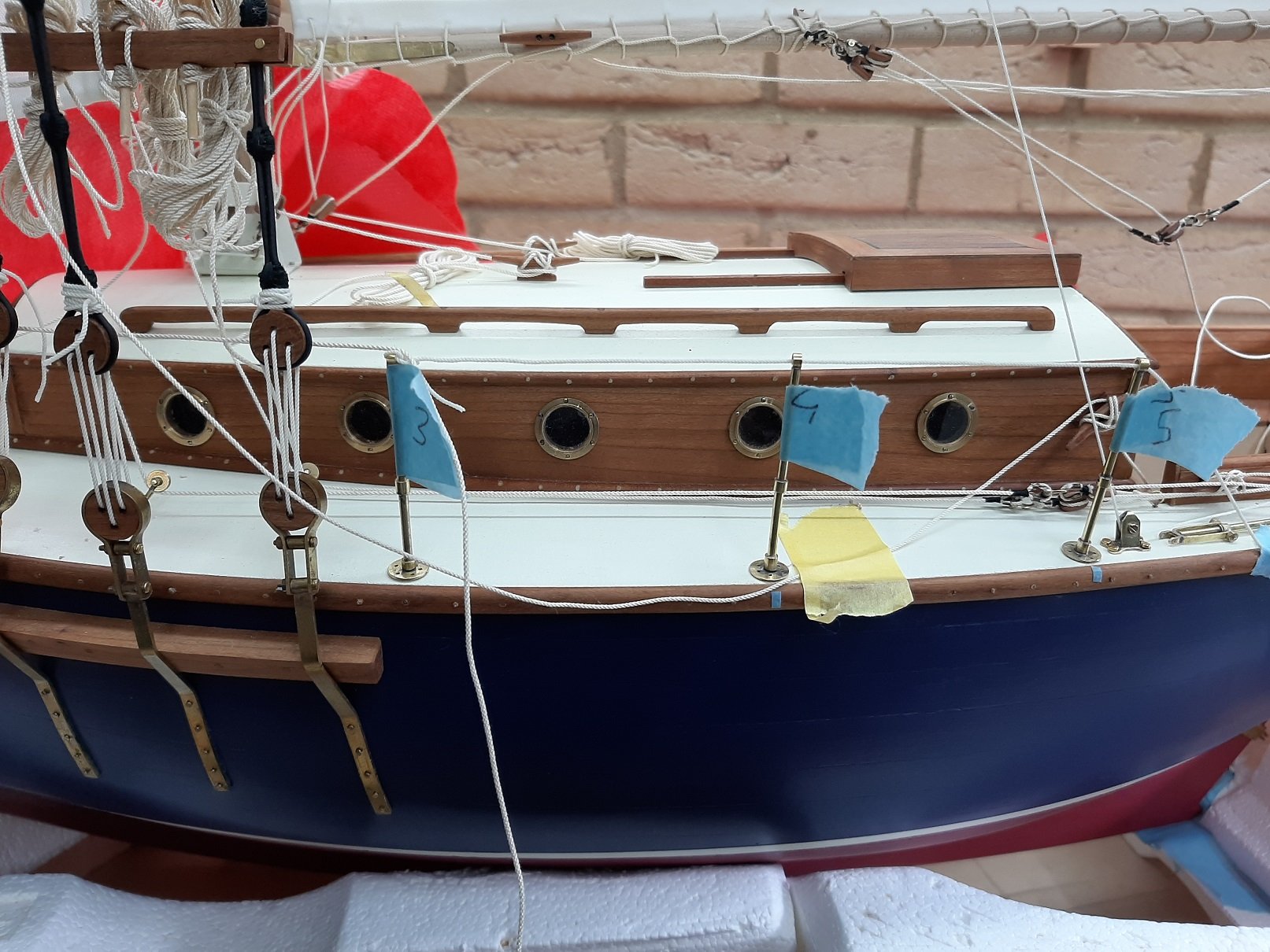
Next photo is the port staysail roller installed. The axle needs trimming


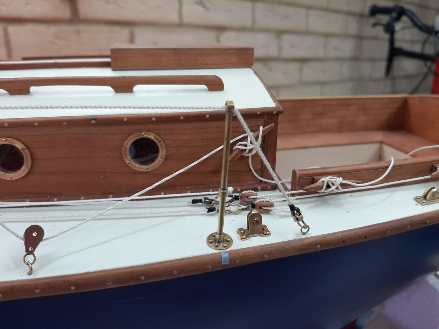
I installed a cleat at the side of the cabin and two on the coaming.
The top jib will be sheeted without any blocks. The flying jib and stay sail will have a single block but it can easily be changed to any other configuration with more blocks.
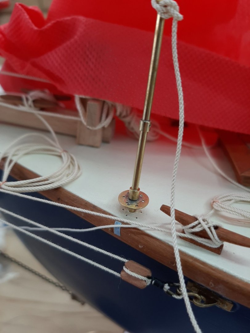
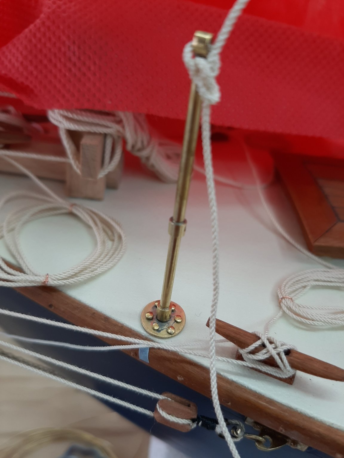
Then I installed the highfield lever and its sheave. The sheave will face quite a lot of pull so I used proper 1.2 mm brass screws to secure it on the deck. I may change the screws with hex bolts but it is not too important
I also drilled 2 mm holes and installed the poles for the rails. This took a lot of head scratching as the rails (which will be ropes going through the poles) need to clear all other lines and components. I think it went well, I still need to drill 6 holes 0.6 mm wide for each pole at the base.
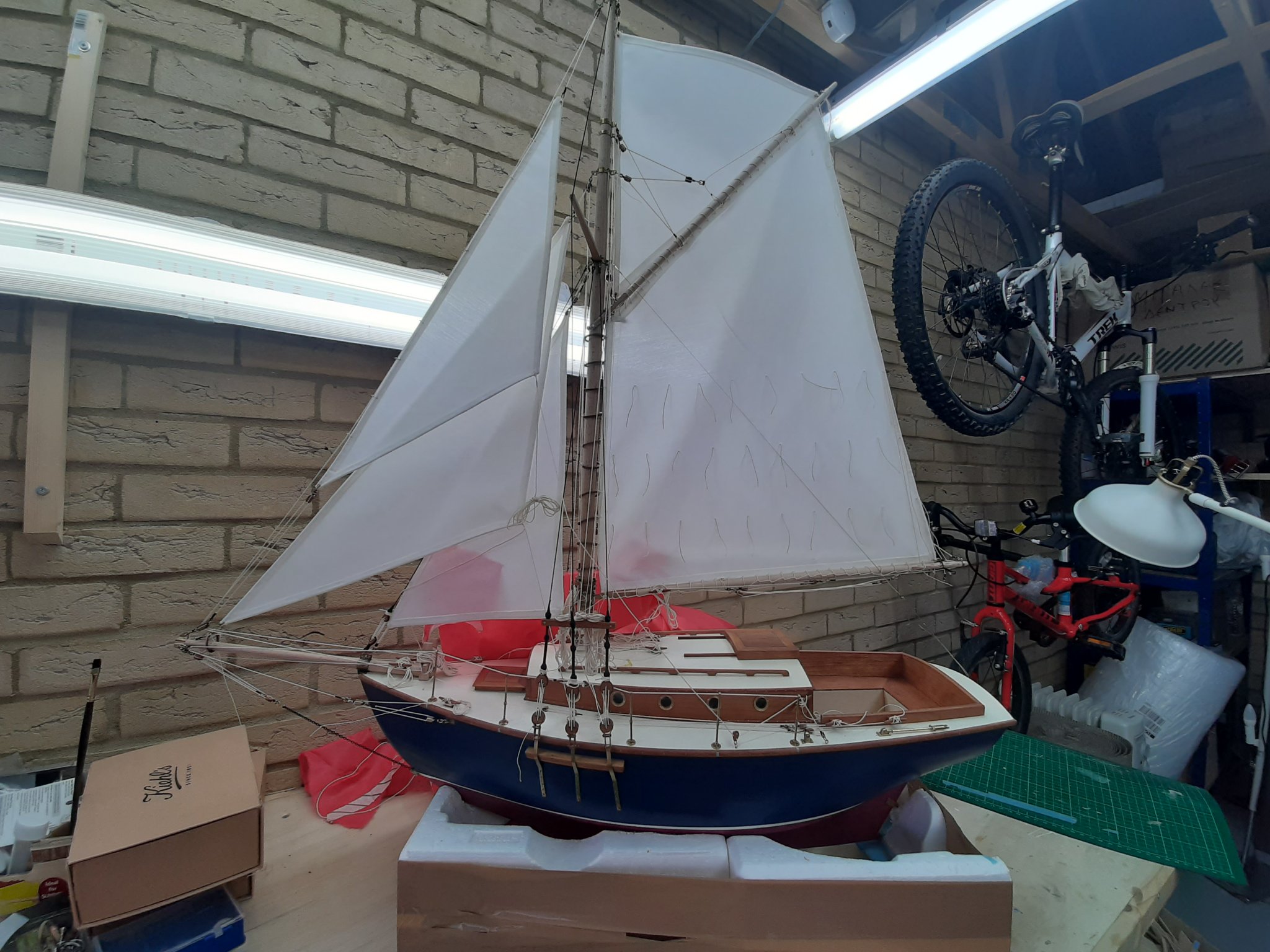
Some photos showing the above


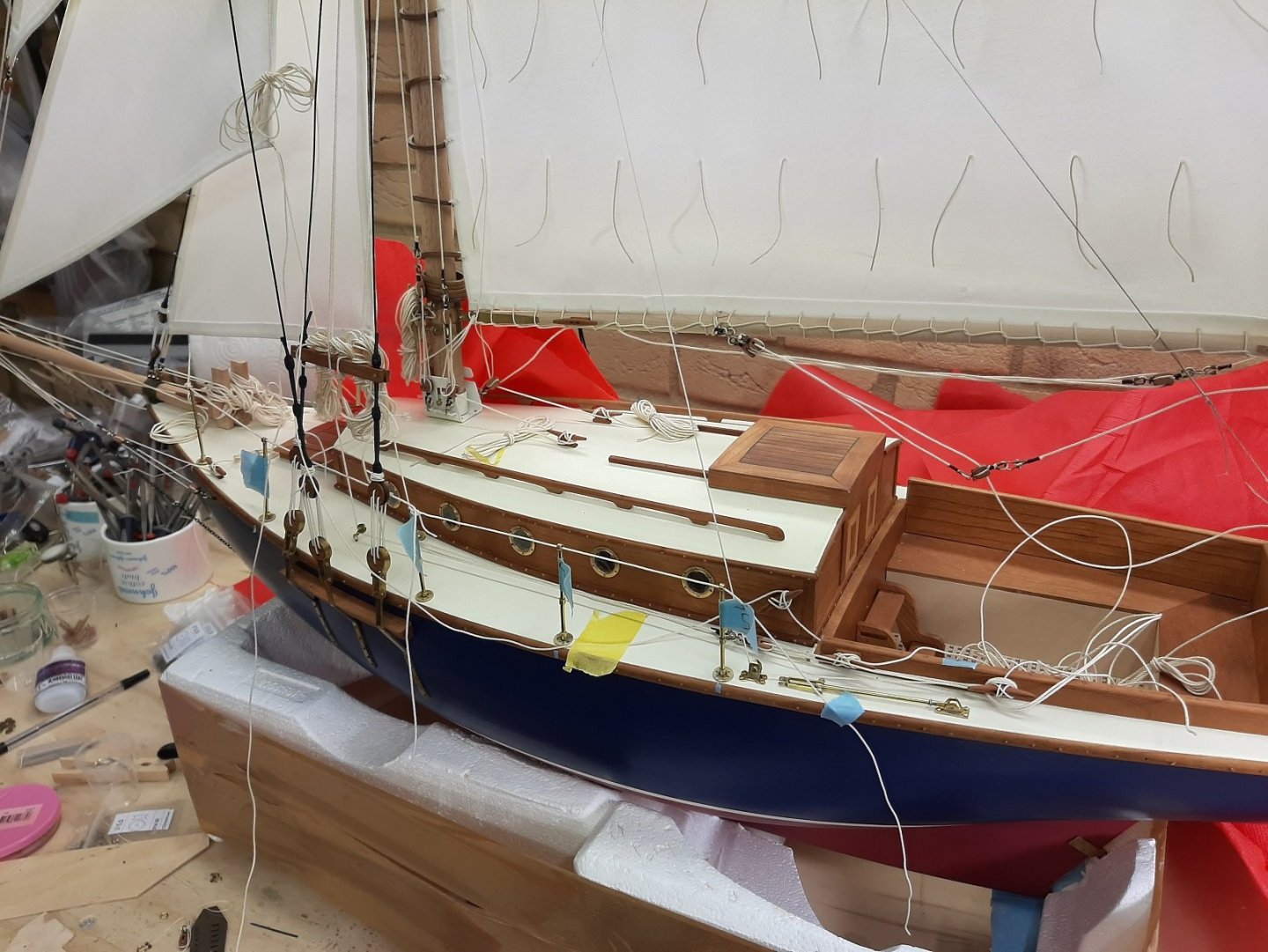
Everything seems to work together and although cramped, so far I ve found space for everything. The sheet for the top jib I do not think will be a problem. I have a vague idea for the mainsheet and I would like to avoid a traveller.
Not far now! I still have no idea what I ll do with the boat when it's finished.
-
-
-
I this a boat? Is it a plane? Is it the cake my daughters made?
Now this is a log I am hooked at. Dying to see where it will lead.
GrandpaPhil you certainly brought colour to our days! Lovely.
- GrandpaPhil, Keith Black, lmagna and 3 others
-
6
-
Looks very good indeed, nice painting. The varnish looks a bit more satin than matt?
I had a look at your site, your models are fantastic!
- Nirvana, Ryland Craze, BobG and 1 other
-
4
-
-
-
So Brian, it seems you are right and that the top view plan is wrong. The planking indeed stops vertical when it meets the rudders and on the other side is the wheel. Somehow the planking continues there.
- mtaylor, mbp521, Keith Black and 1 other
-
4
-
-
-
A very elegant solution! Well done
-
Somethink does not add up. On the side view as well as the photos of the actual boat, the planking reaches the rudders and at that junction the stern appears vertical. On the top view plans though, it is clear that the stern is never vertical. Unless the side planks reach the outside of the rudders vertical but the planking inbetween the two rudders is at a different level and sloped. The side planks seem to indeed stop at the rudders.
Apologies if I am over analysing this, I tend to really over engineer and over loft my hulls!
- mbp521, Keith Black, mtaylor and 1 other
-
4
-


Dorade by Kevin - FINISHED - Amati - 1/20 - renamed Dora - completed March 2021
in - Kit build logs for subjects built from 1901 - Present Day
Posted
Those rings on the sails are almost as big as the portholes! Completely out of scale. Probably better off without.