


Bob Cleek
-
Posts
3,374 -
Joined
-
Last visited
Content Type
Profiles
Forums
Gallery
Events
Posts posted by Bob Cleek
-
-
Ed wrote:
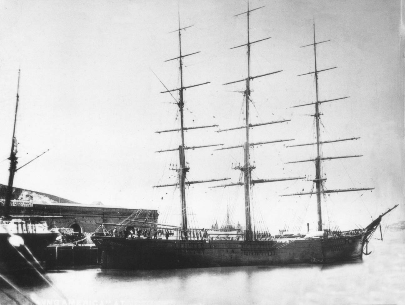
I went back to my sources and found that I had incorrectly placed the forward lift band. My design for the topping lifts is based on the William Crothers drawing for Young America. This drawing is my backup when primary sources are not sufficiently definitive. I believe that his design for the lift - and many other things - was based on meticulous examination of the photographs of the ship as well as other primary sources. So I went back to the photos to determine if there was a basis for his boom lift design. There was. These photos, taken in the 1870's show a shorter boom than the original sail plan, but the forward lift band is clearly visible, as are the lift tackles. Proportionally, the forward band is well aft and the tackles angle toward a midpoint consistent with the placement of the lift bands on the Crothers drawing - and now on my drawing as well. So, your comments and the Niagara replica pictures notwithstanding, I am comfortable with my current configuration.
Ed, you certainly must have far more information on Young America than I will ever have, and, as clippers go, there's a fair amount of documentation on her. What caught my eye was simply the incorrectness of the topping lift rigging, specifically the angle of the forward end of the bridle which, as a matter of physics, has to be in line with, if not preferably forward of the vector of the pendant. If it isn't, the bridle really does nothing mechanically useful. This isn't to say that she might not have actually had the forward end of the bridle attached to that forward band, but unlike yourself, I don't have immediate access to any contemporary photos or drawings which would illustrate that. It was a puzzlement to me that any rigger would rig a topping lift like that, but your comment that her boom was shortened answered the question.
Early contemporary illustrations clearly show that her spanker boom had considerable overhang. Your model depicts her original boom length with a footrope to access the overhang. That boom length is evident in early contemporary illustrations.
_(c112-02-48).jpg.88bfaf801491dccc27080d110fb0fc9e.jpg)
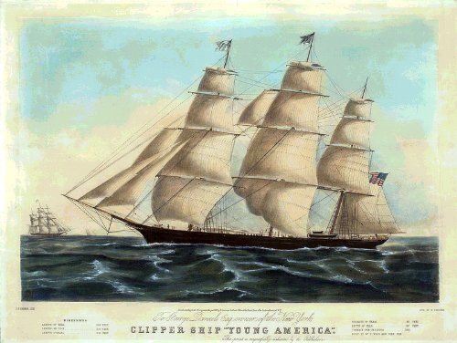
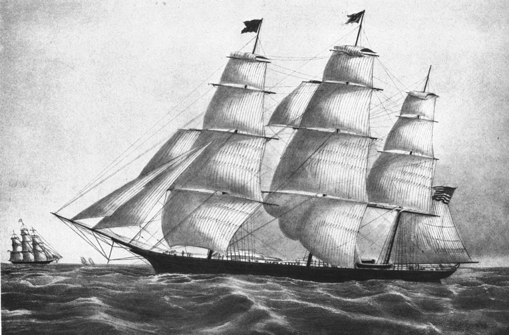
I think it's safe to assume there are no photographs of Young America early in her life. Photography wasn't widely in common use at that time. However, when we look at later photographs of Young America, notably those taken at North Point wharf in San Francisco in 1873, we see that her spanker boom had been "bobbed," with the previous considerable overhang removed.

This photograph (you can enlarge it considerably with your browser's "tools" feature) clearly shows the shortened boom with a boom band slightly ahead of the end of the boom where the spanker sheets are attached and another boom band slightly forward of the wheelbox. It does not appear, from the resolution of the on-line photograph at least, that there is any bridle or lift attached to the aftermost boom band at all. The boom band immediately forward may have a topping lift attached to it, but there is no indication in the picture of any topping lift bridle on the shortened boom and it does not appear to be in the same place as either of the forward two boom bands that you have on your model depicting the original longer boom. Granted, the photo is not razor sharp on my screen and the photo, most likely from a glass plate negative in the J.Porter Shaw collection of the San Francisco Maritime Museum, would probably be much sharper.
Additionally, looking at the photo taken at North Point wharf, if my eyes don't deceive me, it appears that the taper of the boom indicates that the boom in the photo is the original boom cut shorter at its aft end, as the thickest part of the boom appears to be aft of the center of the boom's length. I suggest for your consideration that what in fact occurred was that when the boom was shortened, doing away with the aftermost mast band to which the after end of the topping lift bridles were attached, the riggers simply did away with the bridles entirely and connected the topping lifts to the single band shown in the photo. The bridle would have been intended to spread the lifting tension to two points on the boom and prevent the long boom from bending at its narrow end when being lifted. With a shorter boom, a band at the thicker portion of the shortened boom would have been sufficient to lift the boom without unduly straining it.
If a bridle was retained after bobbing the boom, the after end of the bridle would have been attached to the spanker boom sheet band, thereby moving that point of attachment forward, and, correspondingly, the attachment of the forward bridle end would have had to have been moved forward as well in order to provide for its being angled forward of the vector of the pendant in order to do any work.
We have to recognize, of course, that the photo shows the vessel with all sails sent down (probably sent to Simpson and Fisher, the sail loft nearby at the time, for repairs after a long voyage around the Horn or across the Pacific) and there's no knowing what running rigging they might have sent down for repairs as well at the time the photo was taken. There does not seem to be any boom gallows rigged and her spanker sheets are taken up tightly amidships, so it would appear the topping lift, attached to the forward boom band is doing its job of holding the boom up off the deck.
As for Crothers, I don't have his plans for Young America, but he says in his book, The American-Built Clipper Ship, speaking generally of the spanker boom topping lifts on American clippers:
"The topping lift, which went double, flat against each side of the sail, was made up of a span (bridle,) a pendant, and falls. The span was set up with one point approaching the midpoint of the boom, giving support to its considerable slender length; the other end was set up to the after stop of the boom after the span had been rove through a block which had the pendant turned in. ... Each topping lift was a complete assembly port and starboard, and together they controlled the height at which the boom hung. (See Figure 30.2)" [Op.cit.: p.484]
Figure 30.2, on pages 480 and 481, shows the running rigging of a "representative" clipper ship. That drawing shows a boom with considerable overhang, though not as much as in contemporary illustrations of Young America, with the forward end of the bridle, or span, as Crother's calls it, attached slightly after of the middle of the boom's length and angling forward of the vector of the pendant.
In summary, I entirely agree with Crothers description and drawing of the running rigging of a "representative" clipper ship and would feel safe in assuming such was the arrangement on Young America as she was built, but I would find reliance upon photographs of the vessel when she was long past her prime and cut down for employment in less glamorous enterprises than originally intended suspect authority for rigging details present when she was originally built. Is it possible that your perceived error in the placement of the band you moved aft discovered when examining photographs taken later in her life wasn't an error at all, but rather simply confusion created by the fact that the plans depicted the placement of the band as built and the photo depicted the placement of a band installed in a different place on the boom after her spanker boom was shortened? One would expect that the original band would have been moved forward because the shortening of the boom caused the point of attachment of the after end of the bridle to have been moved forward significantly. Logically, the forward band would have to had been moved forward on the boom about the same distance as the after bridle attachment was moved forward if it were originally attached to the boom end that was cut off. That would have been absolutely necessary to get the bridle angles correct in relation to the pendant's angle. I presume you are modeling her as built, given her original full length boom. In that case, I'd say you'd be safer to rely on Crothers' description in his book than photos taken long after she was built and when her rig had been cut down and place the forward band ahead of where you originally had it so that the forward end of the bridle angled forward of the vector of the pendant when attached to it.
Unfortunately Crothers is apparently no longer with us, so we don't have the luxury of asking him about his plans. If Crothers' rigging plan for Young America does indeed have the forward end of the bridle angled aft of the pendant vector, contradicting his own commentary in his book (not to mention the physics of the arrangement,) there's also always the possibility that he erred in drawing it the way he did. It's certainly not the first time that's happened in published model plans. I hope that possibility doesn't make you too crazy!

-
I know you will probably hate me forever for this, Ed, and I feel terrible about it, but, then again, I feel somehow responsible for it all and can't let it go without a passing mention.
I had written:
Also, note the forward mast band to which the forward topping lifts are attached. It appears to be too far aft to be of any use. Imagine that the topping lift is hauling up the boom. With the forward band where it is now, rather than further forward, the angle of the "pull" is really only pulling the boom forward against the gooseneck and not upwards, as a topping lift should. If the band were placed forward so that the direction of pull of the forward topping lift line were in the other direction, the pull of the pendants would be "up" instead of "forward." If so, they would also better serve as lazy jacks to control the gaff as it came down.
The photos of Niagra posted by Dowmer show the correct lead of the spanker topping lifts. The forward leg of bridle leads from the pendent block at an angle running forward of the angle of the pendant. The band needed to be moved forward on the boom, not aft.
I am truly sorry for any confusion I may have caused. With that, I'll say no more.
-
8 hours ago, rwiederrich said:
... I wonder if these folks might think they are correct.
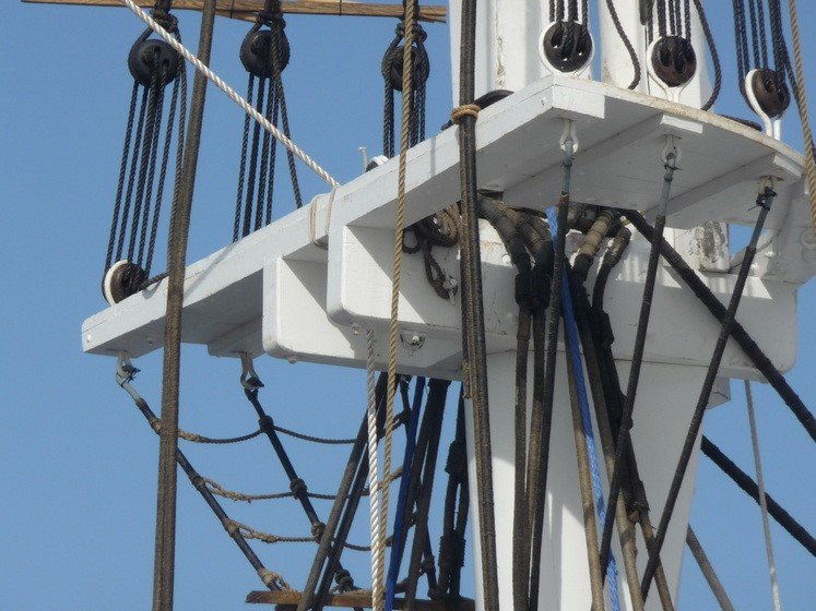
Is that the Morgan? It looks to me like they are using nylon, or some other synthetic line for their lanyards and metal cable for their standing rigging. (if it's the Morgan, I'm sure that's so for the shrouds.) It looks like they haven't finished setting them up, because the bitter ends of the lanyards are hanging free instead of being lashed up against the running part. That one blue line in the shroud gang certainly isn't "period correct." I can't imagine who took the time to do that fiddly cutting in work to paint the metal bands around the lower deadeyes white. Maybe some seaman figured he could skylark for a bit before climbing down to do some work he found more onerous. I can't imagine a bosun putting up with such gimcrackerie back in the days of working sail!
-
12 hours ago, rwiederrich said:
It is unarguable that lanyards are for tightening the shrouds/back stays. Their appropriate tension is the goal to maintain erect, stable masts....and to counter the actions brought upon these members. One can say they are part of an immovable (set) system....others say they are available for adjustment due to warpage and or stretchage. I believe both notions are true. I also believe they had to be preserved in some fasion....to what extent can only been known by time travelers. ...
Rob
For the moment at least, not only by time travelers. Some of us "of a certain age" who grew up around deep-water ports, had fathers in the shipping business, and from earliest memory had an abiding interest in and infatuation with all things maritime, were lucky enough to be able to explore rotting sailing ship hulks on the mud flats without getting caught, make the acquaintance of "old timers" who for a living actually rounded the Horn in the last of the cargo carrying square-rigged sailing ships, informally "apprentice" themselves to master wooden boat builders and shipwrights, sail small gaff-and square-riggerd boats with real deadeyes and lanyards, and generally learn a lot of the "old ways."
-
11 hours ago, EdT said:
All these great comments. I can hardly keep up, but let me try. Bob Cleek raised a number of good points worthy of comment.
At 1600 sq ft, the spanker was Young America's 7th largest sail on the original single topsail rig, with the main and fore topsails being the largest at 2840 and 2600 sqft respectively, followed by the courses. With double topsails it ranks 3rd or 4th in size depending on the crojack size which is not specified on the original sail plan. It was still a lot of canvas. I do not know the method or methods used to take in this sail, but I installed brail blocks on the mizzen mast as well as the other lines shown or those that will be shown in succeeding posts.
Hereafter, in the interests of saving bandwidth, I'll put EdT's comments in bold italics and intersperse my comments in the regular font.
Color of lanyards is a subject that I hesitate to engage in because it is one of those hot buttons that invite many strongly held opinions. I would suggest that someone – not me – create a topic on this subject. I will gladly participate there with my admittedly limited knowledge. I will, however, at the risk of inviting more comments on this build log, contribute here what I believe are some facts:
The color of deadeye lanyards shouldn't be a hot button topic at all. It's really just a matter of historical fact. Some of the modern confusion probably results from 1) a lack of experience and 2) the fact that the color changes over time in use. Also, in small craft, where deadeyes were employed, they may have been designed to be frequently reeved and unreeved, such as the case with a ship's longboats. In that case, line that was not as heavily tarred would have been used. Tarred hemp (not to be confused with "manila" or sisal cordage) is naturally light brown, the darkness of the brown being dependent upon how heavily it is tarred. The more tar, which would be thicker and darker, is applied, and that tar picks up dirt, they quickly darken, eventually to black, or darn close to it, the dirt and tar builds up. The yarns are soaked in thinned tar when the rope is made and that doesn't impart a lot of color, but when tar, and then, often, black paint are applied, the lanyard becomes black. As mentioned in another post in this thread, the tar we are talking about is pine tar or "Stockholm tar," not roofing tar. Additionally, tarred line attracts dirt like a magnet, or so it seems. Much of its darkening is attributable to dirt. The tar will wear, or perhaps more accurately, break down from UV exposure and must be reapplied regularly. However "tan" a tarred lanyard might be, it will be very dark brown, if not black, in a very short while in use.
1. Deadeyes and lanyards were used not only on shrouds but also on backstays.
Yes, that is true in some cases. In others, the backstays were rigged to be tightened with tackles and called "running backstays." These were generally lighter than the "standing backstays" which weren't designed to be tightened, or cast off on the leeward side.
2. On a 3-4 month voyage around Cape Horn, upper masts would be struck down, probably more than once, requiring re-rigging of their stays and shrouds at sea.
Yes, something of a routine task. Their rigging was designed to accomplish this as easily as possible. A good crew could accomplish it easily. A crack naval crew could accomplish it with amazing speed and efficiency, or so it is written. Their deadeyes and lanyards were lighter than the lower deadeyes and lanyards and easier to handle. They needed only to be set up tightly enough not to hang slack when no load was applied to them.
3. Climate variations between say a New York summer at the start of a voyage, equatorial conditions a month later, and semi-arctic conditions at the Cape a month after that, followed by a repeat of those variations up the Pacific, as well as the case described by wefalck, would certainly alter the tension in the standing rigging essential to the support of masts.
The variable factor is not so much temperature, which did have some affect the consistency of the tar to some extent, but rather moisture. This is why standing rigging was wormed, slurried in white lead paste, parceled in tarred canvas, and tightly served with tarred serving line, tarred again, and regularly slurried after being set up using what amounted to black paint in order to keep it dry under all weather conditions. This minimized changes in the properties of the cordage and prevented decay (rot) of the material in the elements.
4. All hemp strands were tarred as part of the rope-making process – hence the straw-color (see Luce, Seamanship 1868). No doubt the effects of sun, salt and weather would lighten this over time.
That's true. New cordage is "straw color," because the strands are soaked in thinned or "diluted" tar, which soaks into the strands easily. That "tar" would be the consistency of water. Un-thinned pine tar is the consistency of motor oil, or even a bit thicker. Weathering does "bleach" tarred line, but it actually tends to turn it grey more than anything else, which is as much dirt as anything. To counteract weathering, tar would be reapplied to lanyards as part of routine maintenance (and often painted black as well.) That and the collection of dirt stuck to the tarred surface, turned them progressively darker and ultimately black or very near so. There is a difference between applying thinned tar to the strands when making up rope and "tarring" lanyards with thicker tar or "slurrying" them with paint to protect them from the elements.
5. The treatment applied to standing rigging discussed in earlier posts, according to primary documentation widely used at the time (again Luce, 1868), can only be described as thick, black, tarry paint. – black due to the carbon black content, thick due to the addition of letharge (lead oxide), tarry due to the pine tar.
Yes, but the "tarry" or "slurry," used on standing rigging is something different from the pine tar used to condition "tarred" cordage. It is indeed "black paint," although I don't believe they added any driers to it, so it remained somewhat flexible and didn't chip and flake much. As with all oil-based paint of the time, its primary ingredient was pine tar, thinned "to taste" with turpentine, litharge, which is another name for lead oxide, red or white, but usually white, which was the primary solid in all paints of the time (later replaced with zinc oxide or "whiting" which was simply talcum or chalk powder,) and "lamp black," (carbon) for color. This paint was cheap and effective. It was applied to the standing rigging to protect it from the elements. (It was also used on ironwork to inhibit rusting. Most all of the iron fittings would have been wrought iron and so already rather resistant to rusting compared to modern steel.)
6. The relatively complex lanyard/deadeye apparatus is obviously designed to add mechanical advantage (6 to 1) to force applied to the lanyard. It was clearly intended for applying tension as the following well known diagram shows.
Yes and no. Lanyards are not "running rigging" per se and while there is a "mechanical advantage" present in the physics of it, it certainly wasn't to provide ease in setting them up! (They look like a block and tackle, but they don't work that way when setting them up because the friction quickly overcomes any mechanical advantage that theoretically existed.) The real purpose of deadeyes is to make it possible to attach a shroud or stay to a fixed point when it couldn't be tied in a knot. There really isn't any other way to set up a thick and somewhat rigid length of standing rigging, except to turn it round the deadeye and secure it with lashings, applying the tension "a bit at a time," distributed through the several turns of the lanyard. The evolution of this piece of rigging is interesting. Originally, a simple lashing served the purpose, but that arrangement created friction which made it more difficult to tighten and chaffed the line as the shrouds alternately went slack or tightened up depending upon whether they were on the windward or leeward side. A "bigger hole" was tried, with large bullseyes, and later with heart-shaped bullseyes with three indentations in the bottom inside of the hole, and, ultimately, the deadeye, which was originally heart- or lozenge-shaped to accommodate more flexible standing rigging, ultimately evolved into the round deadeye which more easily accommodated the thicker and stiffer wormed, parceled, and served shroud-laid standing rigging. The deadeyes and lanyard are essentially an tensionable coupling mechanism that permits the attachment of the standing rigging.
7. Methods and practices have evolved over time. Even early 20th century practices were different than those of the 1860's - and wire was different from hemp.
Of course, but as long as deadeyes were used, they were "mature technology" that wasn't improved upon until the advent of wire cable and turnbuckles. Deadeyes always had tarred hemp lanyards, at least until the advent of synthetic line, which those who used it on yachts often painted black to retain the traditional appearance. Curiously enough, in recent years far stronger synthetic line with negligble stretch has become available and is replacing metal cable standing rigging and turnbuckles, as well as other heavier fittings (e.g. metal sail luff piston hanks) on state-of-the-art racing sailboats. (Dyeema is one well-known brand.) This new line is used with modern "deadeyes" and bullseyes because it is much lighter than the older metal rigging and so increases performance.
So, if I accept the above as facts, I ask the following questions:
1. Why install a large number of contraptions like deadeye/lanyards if they would rarely if ever be used? Why not just seize shrouds/backstays to chains after initial tightening?
As mentioned above, the primary purpose of the deadeyes and lanyards was to provide a way to connect thick and stiff shrouds and stays which could not be tied in a knot to a fixed point while maintaining the tensile strength of the shroud or stay. Three turns of thin line equals one thick one. Secondarily, the arrangement was easily set up and, if necessary, adjusted, and had a certain shock-absorbing ability in distributing the load.
2. If these were needed to re-tension or re-rig backstays or even shrouds, why would one clog up this friction-prone device with a thick, tarry paint?
The tar and/or paint served the purpose of protecting the exposed lanyards from the elements. If re-rigging or re-tensioning were necessary, the cheap tarred hemp lanyards are simply cut away and the deadeye holes cleaned out and greased and new greased tarred hemp lanyards are rove through the deadeyes anew.
3. If greasing rigging with galley slush or other lubricant was common at the time, why would this not be used on deadeye lanyards, at least when needed?
The lanyards and deadeye holes are indeed greased, traditionally with tallow, the all-purpose marine lubricant of the time. (And still damn good today, if you can find it. This is not "galley slush," but a refined animal fat lubricant.) It does not, however, have the weathering abilities of pine tar and remains greasy until it weathers away in the elements. It makes things slippery, but it doesn't last as long as tar or paint and protect things from weathering. Pine tar forms a flexible coating, somewhat akin to varnish. Adding solids (white lead, or chalk) to create a paint keeps the tar where you put it, rather than having it get sticky and thin in hot weather. Dripping tar turned the decks of sailing ships black in short order and, of course, was tracked all over everything and everyone. Naval vessels which, in most navies of the time were kept "Bristol fashion," "holy stoned" their decks regularly. This was essentially sanding the deck back to bare wood with abrasive stone blocks to clean the tar off of them. Painting the standing rigging instead of just adding more raw tar lessened the need to "stone" the decks.
4. What does all this mean to the color of model lanyards?
Well, considering the "scale viewing distance" of a model, and the assumed desire to depict the model as realistically as possible, it means black lanyards. If one were to be building a masted longboat with deadeyes and lanyards which were rove and un-rove each use, it means light brown lanyards, if one is so inclined. "Straw-colorerd" would be too light unless one wanted to show a pristine brand new longboat. Moreover, as a matter of opinion and not historical fact, the contrast of light colored lanyards on a larger vessel have the effect of drawing the viewer's eye to them in a way that distracts from the overall impression of the model. Consider what a real full sized version of the model would look like if you looked at it at full-scale distance and saw "straw colored" lanyards.
I am sure others will approach this issue differently, but this has been my rationale and my reasons for dark, but not black, lanyards.
Of course they will and if they enjoy doing so, that's what it's all about, isn't it? So long as everybody's having a good time. However, if one wants to run with the big dogs, they'd better be black.
Rob, I believe Hervey Garret Smith's comments on deadeyes apply to 20th century yachts, and his description of tar is different than the tar coating described in Luce for application to the "standing" parts of standing rigging. What he describes as a "thin liquid pine oil" would not be black.
Oh, absolutely Hervey Garret Smith was writing for a yachting audience, but he was speaking from his own working experience with deep-water square sail. That said, there were, and still are, some rather large traditional yachts rigged with deadeyes and lanyards and a deadeye and lanyard is a dead eye and lanyard. There's no difference between a yacht and a sailing ship in the way they work or are set up and maintained..
As I explained above, Luce's "slurry" paint is a different coating than pure pine tar. Pine tar thinned with turpentine to a "thin liquid" would not be black, but leave a lanyard made of yarn soaked in "thin liquid pine tar" out in the elements, coat it regularly with thick pine tar "out of the can" the consistency of motor oil and let it get good and dirty, and then "slurry" it with black paint, and those lanyards will be black in no time. It's sort of like if one were building a diorama of an old fashioned gas station on a model train layout: What color is the motor oil that has leaked on the ground? It was "straw colored" when it came out of the can, but it's black when it drips out of the engine.
-
On 10/10/2018 at 11:14 AM, wefalck said:
The story about taking the slack out of shrouds probably comes from the pre-wire rope days, when ships on long equatorial passages stayed for weeks on the same tack. This may have stretched the windward shrouds and slack had to be taken out of the leeward ones because, if a sudden change of tack for whatever reason would be needed, the mast would come over like a whip, risking to snap it.
With wire rope this is not an issue.
Rope shrouds would stretch to some extent when new, but this was no surprise to them. As you may know, they used "shroud-laid" cordage for standing rigging before metal cable came into use. (And metal cable stretches, too.) Shroud-laid cordage is laid up with four strands around a heart, or central, strand. Shroud-laid rope doesn't have the tensile strength of three-strand hawser-laid cordage, but it is designed to be much less liable to stretch, hence its use as standing rigging. When a gang of rigging was made up, the shroud-laid cordage was often wet down and "pre-stretched" beforehand. By the time shroud-laid rope is properly wormed, parceled, and tightly served, and all of that impregnated with white lead paste and pine tar, it's a heck of a lot closer to an iron bar than a rubber band!
I can't imagine a "sudden change of tack" causing a mast to "come over like a whip" in a vessel of the size of Great Republic. Coming about in any square-rigger, and especially a larger one, is a slow, gradual, and rather complex evolution. There's nothing "sudden" about it. Their masts don't "whip."
Lee shrouds and stays will always be slack when the vessel is under sail. That is meant to be. Taking up the slack in lee shrouds while under sail results in seriously over-tensioned shrouds when those lee shrouds become windward shrouds on the opposite tack. A lower mast section might survive such abuse, but such tightening of a smaller upper mast section could even snap it on the opposite tack. I've never heard of a sailing ship heaving to in mid-ocean to take up slack in its standing rigging.
The purpose of the standing rigging isn't simply to "keep the masts from falling down." It's more important function is to distribute the energy loads evenly throughout the vessel's structure. Every part of a vessel moves to a certain extent, and particularly wooden vessels. They are engineered to move so as to minimize shock-loading. Shroud tension is widely misunderstood modernly. We see many modern Marconi (jib-headed) rigged sailboats exhibiting structural damage from shrouds and stays being cranked down with turnbuckles until they sing like violin strings. The mechanics are the same as those of a bow and arrow. Tight shrouds push the heel of the mast downwards like the pointed end of an arrow while pulling up on the chainplates and we frequently see cracked frames and opened garboard seams in wooden boats and even catastrophic chainplate failures and hull fractures in fiberglass boats as a consequence. Shrouds and stays really only need to be tight enough to not be slack when the vessel is at rest. When it is under sail, the windward shrouds and stays tighten up and lee shrouds go slack. Their masts may bend a bit to leeward on each tack until the windward shrouds take up, but that is as it's intended to be.
The "long equatorial passages" by square-rigged sailing ships were almost exclusively made in the Trade Winds because that put the wind at their sterns. The sailing was all reaching and they would do as much as possible to avoid windward work which was certainly not a square-rigger's best point of sail. Reaching put most of the stress on the backstays which in many instances designed as running rigging, particularly those run to the lighter masts aloft. That arrangement accommodated stretch to the extent necessary. Reaching doesn't put a lot of stress on the shrouds, relatively speaking.
- Dowmer and Roger Pellett
-
 2
2
-
4 hours ago, EdT said:
Thank you Druxey. Your comments and input are always well appreciated - and thanks to all who have commented or reacted to the last post.
Wefalck, I cannot say how the spanker was taken in, but it was certainly equipped with the gear to lower the gaff - at least it will be on my model - as will be seen in the upcoming posts on rigging the gaff. I suspect it was able to be furled with the gaff up, since the mast is fitted with brail blocks, which I believe were used for that purpose - plus boom and gaff inhaulers and outhaulers. Others may have more knowledgeable input on this.
Dowmer, I personally do not believe that lanyards were tarred because this would make them very hard to adjust to tension the shrouds and backstays. I rather suspect that they were greased, which would also give them a dark color. I intended mine to be a darker walnut and I may treat them further, but I have been reserving black for tarred lines.
...
Ed
I can't say for sure how the spanker was stuck on the real ship, either, ("different ships, different long splices,") but given the snow mast, which would presumably carry luff hoops on a vessel that size (rather than a laced luff,) I suspect the rig you describe was intended to provide the option of some sort of brailing if desired. There are no "lazy jacks" on the spanker boom, although the topping life rigging appears if would offer the same control of the gaff boom, at least, but perhaps not the sail itself. The spanker is going to be close to, if not the largest sail on the ship and difficult to handle when coming down. This is particularly so, since the spanker boom extends outboard a fair distance, foot ropes or not. The task of "smothering" and lashing down a fore and aft sail is, IMHO, a lot more of a hassle than square sails. The latter usually flutter outward away from the yard when the sheets are started and do not tend to interfere with the job of gathering them up and reefing or lashing them down. A gaff rigged sail comes down on top of you, and in this instance, on top of the helmsman and, in any kind of a blow, will flog all and sundry within range. (And the weight of wet canvas in a sail of that size is not to be underestimated.) I would think the best way to handle this spanker would be to simultaneously lower the gaff boom and haul the clew inboard and the the leech to the extent possible as she comes down, then beat whatever canvas isn't controlled by the clew inhaul, lazy jacks, and brails into submission and stop her up. Were she my ship, I'd be inclined to drop a couple of lazy jacks from the topping lift pendants down and under the spanker boom and back up again on the other side to control the canvas as the gaff boom was lowered. I don't know if that was common practice on ships of that size, though it's quite common in smaller gaff rigged vessels I've known.
As for the color of deadeye lanyards, it is indeed black, or dark brown, tending to black as additional pine tar is added as a matter of routine maintenance. All deadeye lanyards and other similar lashings were of tarred hemp (and still are, if you can find it!) There is rarely, if ever, any need to "adjust the tension" of standing rigging in ships such as this one and deadeye lanyards rarely, if ever, are "adjusted." The lanyards should be pre-stretched when new and, thus, should not stretch appreciably in use. Even if they did stretch when new, they'd only need to be taken up once and the problem would be solved for all time. The sort of rigging we are talking about here was designed to "give" so that the strain on the spars and hull would be minimized. (We're not talking about a "high strung" modern jib-headed Marconi racing rig here.) In fact, the friction generated by the lanyards against the deadeye holes makes them quite difficult to set up, let alone "adjust." The deadeye holes are greased before the tarred hemp lanyard is tightened, but even so, the tightening requires that a purchase clapped onto the shroud be taken to the end of the lanyard in order to get sufficient tension on it. (I've actually had to attach a second purchase on the length of lanyard running from deadeye hole to hole in order to "sweat" the lanyard through all five of the running eyes so that each segment was uniformly tight.) The deadeyes do spread the line stresses in much the same manner as a block purchase, but the lanyards do not run freely as they do in a sheaved block... not by a long shot! When a whole gang of deadeyes and lanyards are made up and fastened with the sheer pole and lashings, all tarred and, modernly, often painted, they are essentially a permanent thing not meant to be untied to be adjusted regularly.
Here's all anybody building models could ever need to know about deadeyes and lanyards, from a website selling full-sized traditional rigging supplies: http://www.woodenboatfittings.com.au/articles/setting-up-shrouds.pdf Perhaps it will serve to eliminate those light-colored lanyards we see so often!
I don't want to sound inappropriately critical, but I'd suggest you take a close look at your spanker boom topping lift rigging. The distance between the pendant purchase tackle appears too short to be of much use. You might want to play with it a bit and see just how much the end of the boom will rise when the tackle is two-blocked. I can't tell for sure, but it looks to me like it would only raise the boom about five feet at most, which isn't much. You can't really know if it is "right" until you consider how high up off the deck the end of the boom is going to be when the sail is set, and then the topping lift would need a bit more "lift" beyond that if it were to be effective. Also, note the forward mast band to which the forward topping lifts are attached. It appears to be too far aft to be of any use. Imagine that the topping lift is hauling up the boom. With the forward band where it is now, rather than further forward, the angle of the "pull" is really only pulling the boom forward against the gooseneck and not upwards, as a topping lift should. If the band were placed forward so that the direction of pull of the forward topping lift line were in the other direction, the pull of the pendants would be "up" instead of "forward." If so, they would also better serve as lazy jacks to control the gaff as it came down.
Great modeling, BTW. I'm really enjoying following your build!
- AON, druxey, paulsutcliffe and 6 others
-
9
-
It may bear noting that Alaska yellow cedar is one of those wood species that is known by many different non-scientific names. Thus, sourcing is outside of its range may be made more difficult if you don't ask for it by the right name. First off, it's not a cedar at all, but rather a cypress. It's known as Nootka cypress, yellow cypress, Alaska cypress, Pacific Coast cedar, Nootka cedar, yellow cedar, Alaska cedar, and Alaska yellow cedar. If you are googling for it, you might try some of its other commercial names, although it is most popularly called Alaska yellow cedar.
Unfortunately, AYC is becoming harder to source for a variety of reasons. 1) Most of it that's commercially logged is sold locally in the Pacific Northwest, where it is still readily available. 2) It's often found in areas which are difficult (i.e. expensive) to access for logging operations. 3) It's dying off throughout much of its range due to climate change and is being considered for classification as endangered. 4) Asian demand for AYC for fine woodwork sends a lot of it off as export. 5) AYC plantation forestry has only just begun to be studied and it more of a challenge than commercial cultivation of other lumber species. 6) AYC is very slow-growing, with a lifespan of well over a thousand years.
It is the winter snowpack that insulates the shallow and fine root systems of AYC trees from freezing. With the snow pack becoming thinner each year, the tree roots are more exposed to cold snaps which freeze their fine root systems close to the surface and kill the trees. Photos of large stands of dead AYC would make you cry, but the good news is that the dead timber is as good for lumber as the fresh for at least 90 years, and perhaps more even. Again, AYC's growing terrain makes commercial harvesting less attractive than more accessible lumber species.

The good news is that while it is considered somewhat rare outside of its natural range, there is plenty of it available in the Pacific Northwest lumberyards. The bad news is that it will cost to ship it elsewhere. I've worked with AYC planking and decking wooden boats and I'm sad to say the offcuts went into the yard dumpster or home for the fireplace. (It's also one of the best fire woods known.) I wish I'd taken more of it for my own "lumberyard" than I did when I had the chance.

- Mike Y, mtaylor, Jolley Roger and 10 others
-
13
-
Doug, I'd hazard to guess that the odds of the two masts on Leon, or any other vessel her size, having differently designed steps is probably very slim unless we are talking about a vessel carrying masts of very different sizes, such as a yawl. Once a vessel gets to a certain size, its heavier scantlings dictate certain construction conventions and Leon is certainly of that "certain size." (She's just over 100', IIRC.) As Leon was designed by Colin Archer, and intended to serve as a North Sea and Baltic cargo vessel, one would probably be safer presuming that the vessel was on the heavier built side than otherwise. Archer's design portfolio is relatively well-documented, I believe. I'm familiar with his famous lifeboats and their derivatives, but not his larger designs. Naval architects being what they are, it's to be expected that their body of work will exhibit similarities in certain engineering features and mast steps would likely be one such feature. As a naval architect and ship builder rolled into one, Archer designed and built Leon in his own shipyard, so the likelihood of certain engineering features like mast steps being "stock features" repeated from build to build becomes even greater. However, the catch is that in the case of his smaller vessels, at least, there never were any construction details drawn. These were worked out on the loft floor and determined in situ, as it were. To make matters worse, reportedly, his draftsmanship is notoriously sloppy. Since he was running the yard, he didn't need to communicate with the shipwrights on paper as much as a naval architect whose drawings were going to have to be followed by a separately-managed and often remotely located yard would have. Copies of Archer's original drawings, such as they are, can be obtained from the Norwegian Maritime Museum's library in Oslo: Norsk Sjofartsmuseum, Bygdonesveien. https://marmuseum.no/en/
A quick google search for plans of Archer's larger vessels on line turned up nothing, but I did come across one "for sale" listing of a yacht fairly recently built to Archer's plans as a replica of the original design. There were two photos of the mast step of this 23' Archer-designed sloop on line which clearly show what, for a boat that size, was quite a solid mast step designed to spread the load across the floors and frames as well as the keel itself. It appears to be of composite construction, with some of the knee structure of metal plate. Many other designers would opt for a mast step made of a mortised block fastened to the keel alone in a small sloop like this one. Until you can finds the construction drawings for Leon, or at least for Fram, I'd say you'd be safest opting for the more complex, but more strongly engineered, type of mast step. I wasn't able to copy the photos, which seem to be encrypted, but they can be found at https://www.woodenships.co.uk/sailing-yachts/colin-archer-yacht/ Conveniently, for our purposes, the mast step structure pictured is painted white.
-
On 10/4/2018 at 4:43 PM, Doug McKenzie said:
"... Bob, it is interesting to me that you imply that Leon is a pretty good sized ship. I've always thought of her as being small. Oh, btw, when you say mainmast, I assume you mean the square rigged foremast. I don't quite know how to ask this, Bob, but can you give me any info on how you make the judgement that "given her size, I'd have expected that she'd have a properly built step."
I only referenced a comparison between Leon's size and what I would expect to be the scantlings and construction of a mainmast step of a vessel of her size, type, and "modern" build. Like a lot of things where "size matters," our assessments often differ because they are necessarily relative. Obviously, your mileage differs.
In addressing the mainmast, I intended to signify nothing more than that it was presumably the largest mast step on the vessel. My reference to a "properly built step" wasn't artful. I meant to convey a "a proper built up step" without implying there was anything wrong with a mortise block on top a a keel or keelson in much smaller vessels than Leon.
My assessment was based on over fifty years of exposure to mast steps in full-sized wooden vessels of many types and the stresses mast steps are designed to withstand. In Leon's case, I'd expect to see something more than a mast simply stepped on a mortise block mounted on top of a keel or keelson. Of course, if contemporary data on this specific vessel has become available since the time of Underhill's writing, that should resolve the question. I was being polite in giving Underhill the benefit of the doubt as to accuracy. In recent times, the historian's caveat that "scarce information isn't necessarily accurate information" has been proven time and time again. I think there are two factors at work in this respect. 1) In earlier times, the standards for accuracy and completeness probably weren't as high as now. A lot of blanks were filled in with assumptions and guesses. and 2) There were so few interested in recording and addressing the data that there was nobody to "proofread" their work product. For example, this is a big issue with the HAMMS data, much of which comprises of lines taken off or copied from earlier incomplete drafts by unemployed non-maritime surveyors and draftsmen in the course of a WPA "make-work" project the inaccuracies of which, at the time, were of far less interest, and certainly far less consequence, than now.
The original poster offers a drawing from Crothers' book, American Built Packet and Freighters in the 1850s, noting that "A much more complicated arrangement shown in the attached diagram is given as the most common arrangement designed to spread both the weight of the mast and the stresses over a larger area." I doubt that the fact that Crothers was addressing mid-Nineteenth Century American construction practices and that Leon was built in the late Nineteenth Century in Norway would make much difference. Crothers' report has been my observation as well, although my experience is negligibly authoritative compared to Mr. Crothers' academic research.
-
You'd have some significant challenges making scale ring bolts that would withstand the recoil!
- allanyed, CaptainSteve, mtaylor and 1 other
-
4
-
On 4/15/2018 at 2:11 AM, shipman said:
Hi,
forgive me if this is the wrong area to ask this question.
Perhaps it's been covered in the past, however, it's occurred to me, for extreme miniatures, has anyone any experience using human hair for rigging? Judging by the age of Victorian 'momento moiry', hair lasts forever and surely would be a better substitute than nylon mono-filament, very thin wire or stretched plastic sprue which are commonly used. And at these scales hair is a lot stronger and comes in a variety of colours.
I'd appreciate feedback on the topic, thank you.
I believe some of the Napoleonic bone prisoner of war models are rigged with human hair. As most probably know, sailors of that era let their hair grow out on long voyages and kept it tarred to keep it clean and under control. At the end of a voyage, they'd sell it to the wig makers, who'd wash the tar out and card it. (Hence the classic sailor's uniform "middie" back collar, which kept the tar off their shirts when their hair hung down in a braid and the custom of calling sailors "tars.")
Horsehair is more commonly used for many purposes similar to rigging line. It's readily obtainable in various thicknesses and degrees of stiffness and softness and comes in lengths up to around 48". The light colors take dye readily.. The "craft quality" ("cheap") stuff will run you around $900 a pound, though. The highest quality white horsehair, which is used for stringed instrument bows, is priced much higher. http://hairwork.com/horse_hair_for_sale.htm
If it's really fine thread you're looking for, my guess is your best bet would be surgical suture thread. (Just don't use the "absorbable" type!) The famous "miniaturist" ship modelers like Mc Nalley and Mc Caffery actually used very fine wire for their rigging.
Everybody uses the "tarred" nylon seine twine these days and it's great for full-sized rigging applications. Years ago, real tarred marline was available. It wasn't as strong and tended to be "lumpy," but there was nothing that smelled as good as real Stockholm tar. You can still get Stockholm tar, and regular pine tar (sold in feed stores for coating the sides of horses' hoofs.) You can thin pine tar and soak line in it to get tarred line. Pine tar used to be a shipboard staple in the days of sail, of course.
-
I'm surprised that Underhill, who I don't doubt, found that Leon only had a block on the keelson. Given her size, I'd have expected that she'd have had a properly built up step as pictured above, for the mainmast, at least. I also note that the drawing above omits the limber holes in the knees and the bottom of the mortise. That tenon isn't something you want rotting away on you!
- mtaylor and thibaultron
-
2
-
Your work is a joy to behold! I've hung my share of full-size coiled falls on belaying pins in my day and I can confirm that your deciding to hang them as you have is correct. It's done as pictured on the Joseph Conrad above, although it looks like in that picture a few more turns around the pin than is necessary (or properly shipshape) have been taken. Correctly, the fall is brought down and beneath the rail, behind the bottom of the pin, up and across and behind the top of the pin, back down and hitched over the top of the pin. More than one "figure eight" around the pin only makes for more work casting the line off the pin.
The 1870's picture of the Inuit kids on the deck also shows the coils correctly hung on the pins, although, as is clear from all the cargo and gear on deck, the vessel wasn't sailing and they were probably working on the rigging and not too particular about it at the moment, as things certainly aren't "shipshape." Still, any able seaman would automatically coil the fall into one hand, or on deck if it were too long to hold in one hand, starting at the pin end and leaving a length free from the pin, imparting a half-twist as each coil was measured out at arm's length, so the laid line would not kink, and when the fall was fully coiled, present it to the pin and reach through the center of the coil and grab the length of line between the coil and the pin, giving it a turn, or two, depending upon it's length, pulling the twisted line back through the center of the coil and up in front of the coil and over the top of the pin. (For lighter lines, one can take a longer length between the pin and coil and take a couple of turns around the coil with it to gather the coil together, and then bring it through the coil above the turn and place it over the pin. This will gather the coil of light line tightly and more neatly.) In this fashion, the loop over the top of the pin could be cast free and the coil fall to the deck, the side closest to the pin facing upwards, and the coiled fall will be ready to run free without fouling. Any seaman that failed to do it that way back in the day would likely get the bosun's start across his back! LOLI don't know how many otherwise exquisite models I've seen with the coiled falls simply hung over the pins. It should be easy to imagine the consequence of that in heavy weather with decks awash... the deck would soon be a rat's nest of tangled cordage! Another frequently seen "faux pas" are coils that are the wrong size. Each coil should be as long as is necessary for that part of the rigging to run as intended. If the line, such as a headsail halyard, runs to the top of a headstay, then the belayed coil when the sail is set should be made up of a length of line equal to the distance to the halyard block. Were it shorter, the bitter end of the halyard would run aloft and out of reach when the sail was struck. Coils on a pin rail if neatly done should all be about the same length, pin to deck, but of different girths, reflecting the amount of line properly needed. That detail is very frequently overlooked, even on otherwise very well-done models. Then there are the all-too-common "white" deadeye lanyards which in practice are always tarred "black," ... misplaced and oversized trunnels, plank butts on frames, ... and overly long planks... but I digress.
I'd probably be a very unpopular model competition judge, but whether or not a model was built by a modeler with a command of full-sized shipbuilding practices and marlinspike seamanship is immediately obvious to the "sailor's eye." My obnoxious pontification isn't intended as a criticism, but rather to point out that you've illustrated here the correct way to do it and to offer the observation to those "landsmen" who otherwise must rely on instructions that come with a kit that learning to "think like a sailor" will avoid such pitfalls.
- capnharv2, billocrates, druxey and 12 others
-
15
-
Stop the presses! You're way ahead of yourself. 1) It's better to scrape the laser char from the edges than it is to sand them because sanding will tend to round the edges, which you don't want to happen. 2) Use caution painting or staining. Always consider whether a coating on the wood will impair the strength of glue bonds.
The answer to your questions about the "double" keel and stem pieces is contained in the first page of Chuck Passaro's "build log" at
in this forum. (Click on the link box above.) Chuck designed this Model Shipways kit. (His build log is among several listed in the "Build Logs/kit models/small craft" section of this forum.) Chuck's log is beautifully photographed and his step-by-step explanations are fool-proof. He's always open to questions and is most generous in giving his time to share his experience with we lesser mortals. (I'd put him in the "National Treasure" category when it comes to ship modeling.) If you follow his build log precisely, you won't end up making mistakes and getting frustrated. As will everybody else, I expect, I would also suggest you obtain after-market blocks and rigging line from Chuck's Syren Ship Model Company, a sponsor of this forum. His line and blocks are "finestkind" and much better than what the kit manufacturers provide.
Read Chuck's build log from beginning to end and then do the same for some of the other "finished" build logs of this very well done model before you go any further. When you've done that, you won't be a "beginner" anymore!
- vossy, mtaylor and pontiachedmark
-
3
-
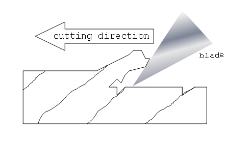
Being that it is "ultrasonic," I expect it's efficiency depends upon the rigidity of the material being cut. It would operate similar to a Fein multitool, or the various knock-offs of that which operate on the principle of an orthopedic cast saw. The minutely vibrating saw blade will cut the rigid plaster cast, but not the skin beneath. Up against hard styrene plastic, it pretty much does quite well. I wonder how a hobby knife blade, designed for cutting, now sawing, would do in it when cutting wood, and particularly soft wood, which is cut by shearing in that application. If a fine-toothed saw blade were available for it, I expect it would saw like a miniature multitool saw blade.
It probably costs a fair amount. The question would be does it do the job better? Is it more accurate or does it work more quickly? Does it produce better or faster work? Or is it just another gizmo? It's clearly a "mousetrap," but is it a "better mousetrap?"
-
-
Without comment on whether the model (partially) in the photos is worthy of museum display, I'm surprised that a museum of Mystic Seaport's stature would display a model so obviously in need of conservation. Not only are the anchors corroding, but the copper bands on the stock are broken (perhaps by the expansion of the lead oxide beneath the stock halves,) but also there are rigging chains detached and hanging loose and staining on the base from apparent condensation. Not only have some copper plates come adrift, but the coppering and parts of the chains in the close-ups appears to have developed a green patina betraying that it has been stored in some time in an excessively humid environment. Among curators, these are obvious problems that require prompt attention. Perhaps Mystic simply left it on display pending future-scheduled restoration.
If anyone is interested in what seems to be the "last word" on ship model lead corrosion, the USN NAVSEASYSCOM's research report is highly informative. It can be found on line here: https://www.navsea.navy.mil/Home/Warfare-Centers/NSWC-Carderock/Resources/Curator-of-Navy-Ship-Models/Lead-Corrosion-in-Exhibition-Ship-Models/
-
Think of the tree as a long, narrow cone-shaped bundle of cone-shaped straws pointing upwards. If you planed downwards, but parallel to the straws in the cone, you'd be planning with the grain and, similarly, when you plain upwards, parallel to the straws, you'd be planning with the grain as well. It's only when the wood is milled and squared that you have what is called "grain runout" because to cut a square plank out of a cone of straws is going to cut through some of the straws. If you hit the edges of the cut straws head on when planning the side of the plank, you are "cutting against the grain."
Then there are trees which have their cones twisting in a spiral fashion from bottom to top, called "spiral grain," and there are those which have their straws all twisted up in various directions from bottom to top, called "interlocking grain."
If your plane is properly set and starts to chatter and dig in, time to plane in the opposite direction.
-
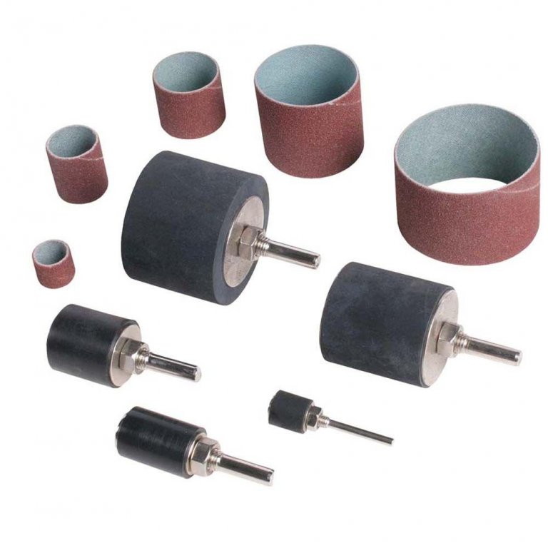
I realize the inquiry was about a "dedicated spindle sander, not a drill press or moto tool," but I have to say that IMHO a "dedicated spindle sander" for modeling is really one of those things (if such truly exists) that is overkill. I agree with Jager that there's no point to oscillation. This is primarily because nobody is going to be hogging off large blocks of wood when modeling and, if one operates the sander properly, there should be little or no wood clogging or undue abrasive wear. (I.e.: let the sander do the work and don't press the work hard into the drum.)
I have used a Delta drum sanding kit designed for use in a drill press for years and have been entirely satisfied with it. (Again, the Morse taper of a drill press chuck isn't designed to take lateral force, but this isn't a problem if little lateral force is applied with the work piece, as is proper.) A used bench top drill press is easy to come by on Craigslist or a garage sale for relatively little money and if used as a dedicated drum sander, it can always double as a back-up drill press. If you already have a drill press, so much the better.
Using hole saws, I have cut a selection of holes to match the size of the drums from 1" plywood. I've also cut a couple extra with holes to fit the largest drum. By stacking up these "zero clearance inserts" (the big ones beneath the smaller holed ones, as needed) clamped to the table and adjusting the quill and setting that as convenient, I can always move the abrasive area exposed as needed to always have an unworn section of abrasive presented to the work piece. A crepe rubber abrasive cleaner used as needed ensures that the abrasive doesn't wear prematurely.
I have a plastic tube that fits my shop-vac hose and has a rare earth magnet epoxied onto it. This tube holds the hose beneath the center of the drill press table top and pretty much sucks most of the sawdust away from down below.
It's really no more trouble than chucking a drill bit into the chuck and sticking my shop-vac hose to the bottom of the drill press table, so my drill press not being "dedicated" to sanding has never been an issue for me.
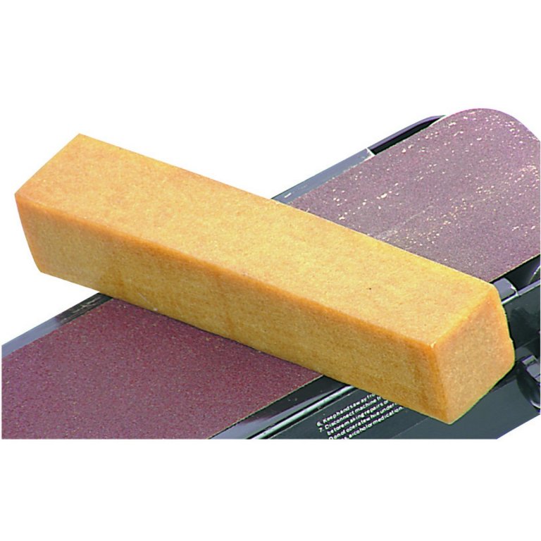
It's a stock Home Despot item for forty bucks: https://www.homedepot.com/p/Delta-Sanding-Drum-Set-25-Pieces-17-940/203293688 Harbor Freight has them for twenty-seven bucks less the abrasive sleeves: https://www.harborfreight.com/4-piece-quick-change-sanding-drum-set-35455.html Horror Fright has the crepe abrasive cleaners for eight bucks, too: https://www.harborfreight.com/sanding-belt-cleaner-30766.html
Just sayin'. Your mileage may vary.
-
They are indeed both Model Shipways kits which have been in production long enough to have "gotten the bugs out" of them. I've not built either of them, but I'm familiar with MS kits and they are of excellent quality. I'd offer a few off the top of my head observations.
1) The websites you posted have links to comments on the models which should give you more of an idea of what they are.
2) The MSW "kit builds" build log index I am sure has several build logs for each and these will get you tons of information on what building them is actually like.
3) If you want to do a really good job on either model, expect to replace the kit-provided blocks and deadeyes, the rigging line, and sailcloth with higher end after-market ones. (Syren Ship Models is your friend here. They won't break the bank.)
4) The Latham is by Eric Ronnberg and Bluenose is by Lankford, both highly respected and very well known modelers whose written instructions that come with the kits are excellent. You shouldn't have any problems following the instructions and the more than adequate MS plans.
5) The Lattham is scaled at 1/4" = 1', while the Bluenose is scaled at 3/16" = 1'. This may not seem to be much of a difference, but the larger 1/4" scale Latham will be easier to build and likely have more detail which will result in a more interesting model to build and to view. Apparently, Latham is depicted in her working condition (and includes a seine boat, as well, a cool feature.) The Latham provides the opportunity to "tell a story" of what that fishery was like. While not to run it down unreasonably, Bluenose is apparently depicted in her "racing trim" and not as a working Banks dory fisherman, so it may be a less interesting model, although that is just my own opinion.
5) There's not a lot of difference in the size of the finished models, but you should probably give some thought to the size of one versus the other and determine for yourself if "size matters." Take some sticks and build "storey poles" to give an idea of how much space each would take up when cased (and any good model should be cased if it is to last for any length of time and not just turn into a "dust catcher.") How much space to give a model in its case is something of an artistic determination, but for models of these sizes, I'd expect to have to allow a minimum of somewhere between 2" and 3" more that the extreme dimensions of the finished model, top and bottom and side to side all around. (Often, the fore and aft dimension of the case should allow for greater space so that when the model is viewed from at least a 45 degree angle, the view of the entire model is not obscured by the corner post.) That often becomes a surprisingly big "box." It always surprises me how much space the cases take up after spending the time with my nose glued to the work building such tiny details!) and it's going to dominate most any room in a house, or at least be the visual focal point. I hate to admit it, but all the models I've made or restored in that size range are in my office or on display in the yacht club. The only ones I've been able to find a place for at home without spousal objection are smaller models half or less the size of the ones you're contemplating.
- Canute, mtaylor and uss frolick
-
3
-
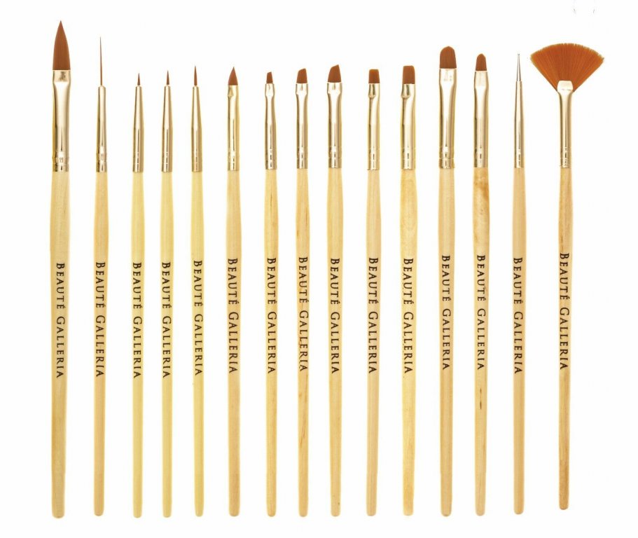
In the beauty supply department, I've also noticed that on eBay, at least, micro-fine paint brushes are a fraction of the cost they ask in the model building catalogs when sold for painting ladies' fingernails. Apparently, those custom-painted manicure jobs that are popular require very small size brushes. The same goes for those very soft bristle brushes used for "weathering" detailing. Seven bucks for the below set on FleaBay: https://www.ebay.com/itm/15pcs-Acrylic-Nail-Brush-for-Detailing-Striping-Painting-One-Stroke-Liner-3D-Gel/162517019512?epid=12021083820&hash=item25d6c4eb78:g:R1gAAOSwYxBaDEz6:sc:USPSFirstClass!94952!US!-1
-
2 hours ago, barkeater said:
There is a good discussion on the Wood Database concerning exotic woods and their losing color. It seems that all but a few woods will lose or change color with aging. Yellowheart which was mentioned in this discussion only darkens slightly and I'm using it for the yellow ochre stripe along the gun ports of Unite. I'm also using Chatke to simulate the red paint on the gun deck. This however may be a bad choice as this wood turns brown with age. I decided not to go with dyed wood even though the color was very similar to Chatke because it was dyed. I will seal it very well hopefully with shellac and dulcote varnish but in a few years my red may turn brown. What I'm getting at is that this is a personal choice and there is a good discussion on the database on this. Is it more important to have the colors of you project last or can you accept that the vibrant color that looked so nice may not be permanent. Another coat of shellac for me but to each his own.
Indeed, the colors of "naturally colored" wood are rarely stable and most do lose their original color rather quickly and this is particularly so for "reds" and "purples.". I can't say this authoritatively, but I suspect that your chatke may hold its color longer if you apply a high quality marine spar varnish with a fair amount of UV inhibitors in it. (Which may require some thinning, and rubbing if you want to knock the high gloss off of it) A light coat should not impart too much of a brown cast from the varnish and the UV inhibitor will block the UV that is the primary cause of fading. (Epiphanes is a well-respected brand.)
-
But I digressed, didn't I? Sorry about that.
To get right to the point with my two cents worth (Usual disclaimers apply. Your mileage may vary.)
1. Tools. I see there are various tool kits offered on the web and wondered if these are workable for the beginner. Do brands make a difference? Tools needed but not included in these kits? Tools / supplies you find indispensable?
I wouldn't advise paying much money for the so-advertised "ship modeling tool kits" because 1) they usually contain a number of unnecessary, if not useless, tools and 2) are almost always Chinese-made knock-offs of higher quality American-made tools. For example, most will look like they contain hobby knives made by X-Acto, but aren't. A couple of real X-Acto handles and a selection of blades will probably cost half of what a knock-off kit costs and you don't need the extraneous tools in the cheaper kit anyway. The X-Acto blades will be of far higher quality than the Asian knock-offs and the handles will be made of better metal and plastic and will hold the blades firmly, unlike the cheapo copies. Of course, if a retailer is throwing in a "tool kit" in an introductory kit, it's better than a poke in the eye with a sharp stick... or X-Acto knife, as the case may be.
Yes, brands do make a difference. The "level" of the tool makes a difference, too. There is a reason even X-Acto knives are called "hobby knives" instead of "surgical scalpels." (They were invented to be surgical scalpels, but weren't accepted by the medical profession because they couldn't be sterilized easily.) For light, delicate, work, a surgical scalpel and blades will do a better job and probably at a lower price point. Buy the professional grade tool whenever possible. You will see selections of Asian pliers sold in the hobby catalogs. For very little more money, you can buy pliers made for orthodontists in dental catalogs of much higher quality.
2. Workstation. Do you find a standard table and chair height comfortable or does a workbench with taller stool a better choice? Seeing this work demands time and patience I would think comfort is key. How much work space is required? Lighting?
It's a matter of personal preference. Myself, a standard table and chair often puts the work a bit too high and definitely so when working on rigging that may be a foot or more above the table top. I generally work on a bench and sit on a drafting stool which has an adjustable seat and footrest so I can raise myself to whatever height is most comfortable and can easily hop on and off to get things from the shop as needed. (These are a pretty common Craigslist or garage sale item available at low cost.)
Workspace is also a matter of personal preference and availability. Some find card tables enough. I built my first wooden ship model on our desk in a one bedroom apartment when my wife and I were in graduate school. I prefer a stable bench, particularly because you really can't mount even a small jeweler's vise on a card table and expect to get much done without it jiggling around. These days, I enjoy the luxury of a fully equipped workshop in an outbuilding that houses the spoils of a lifetime of used tool collecting. (Cleek's Law: "Tools expand to fill the space allotted." I call it a collection. My wife calls it an addiction. ) I have a separate "surgically clean" room for my drafting table, plans storage, modeling library and a couple of "clean" benches, one a very sturdy metal machinists bench for working on rigging and small bits. The rest of the shop outside of this is the "dirty shop" that houses a battery of standard-sized stationary machine tools for full-sized boatbuilding as well as a collection of Byrnes modeling machines, a Unimat micro-lathe/mill and scroll saws, and my "woodpile. (I also work on full-sized classic wooden boats.) This is where I do anything dusty, greasy, or otherwise messy, like airbrushing and spray painting. Between that and the kitchen table, desk or card table upon which most of us started out lies the spectrum of what somebody would "need" and somebody would "want" for building models. What I have at my disposal is admittedly luxuriously excessive. It's well beyond what's required to build the finest ship models, but, then again, at this point I can mill my own wood and build my own display cases and it costs me next to nothing. (Other people's discarded furniture is sometimes a great source of modeling hardwood!) I must be the first to admit that it's very easy to wake up one morning and realize you have more tools than skills to get the most out of them.
Joking about "the Admiral" aside, one does have to consider the others we live with. It's a royal pain to have to "set up" and "take down" your modeling workspace each time you want to work on your model and others often complain about paint fumes and sawdust in "their space." (We won't even begin to talk about what happens when your wife catches you melting a pot of lead on her kitchen stove!
) If one can find so much as a government surplus metal office desk to keep in a space they can call their own, so much the better. Again here, your mileage may vary. The famous naval architect, L. Francis Herreshoff, who never married and lived alone all his life, enjoyed the luxury of keeping his metal lathe in the dining room of his home. We should all be so lucky!
As for lighting, the more the better. I have a collection (garage sales again) of articulated drafting lamps ("Luxo lamps") and fluorescent ring tube articulated magnifying lamps that clamp on bench tops. These provide strong light directly on the working area and can be moved around to direct the light right where you want it. Some prefer various magnifying lenses worn like eyeglasses. Others, as myself, prefer to work beneath an articulated magnifying fluorescent lamp or use the traditional jeweler's swing-down magnifying lens that clips to the temple of our eyeglasses for fine work.


Young America 1853 by EdT - FINISHED - extreme clipper
in - Build logs for subjects built 1851 - 1900
Posted
I am tempted to take issue with a number of points in your latest post where I disagree, but in the interest of time will instead focus on your final point, one item that I believe we agree on: The location of my span shackles are almost precisely proportional to Crothers' representative drawing in his first book, which you "entirely agree with" as well as his model drawings.
My copy of Crothers' book has the forward end of the span fastened ahead of where the vector line of the pendant crosses the boom, of that I am sure. No matter, though. I know the "weary" factor well. About forty years ago, early in my adult model building "career," I built a kit model of the Mary Taylor in 1/8" scale. When all was said and done, I belatedly realized that I'd put all the deadeyes in upside down, with the middle hole on the bottom instead of the top. I have no idea why I did that, and it was intentional at the time. I just did one that way and made the rest the same, without giving it a second thought, even though at that time I owed a full-sized boat rigged correctly with deadeyes and lanyards! Just your basic brain fhart, I guess. I never re-did them. The model, in a nice glass case, has sat in my office since then and many have complemented it. Nobody's ever noticed the upside down deadeyes!