

scrubbyj427
-
Posts
1,700 -
Joined
-
Last visited
Content Type
Profiles
Forums
Gallery
Events
Everything posted by scrubbyj427
-
 Stifflers Mom… better clean up your sawdust promptly, Frank. Lol.
 -
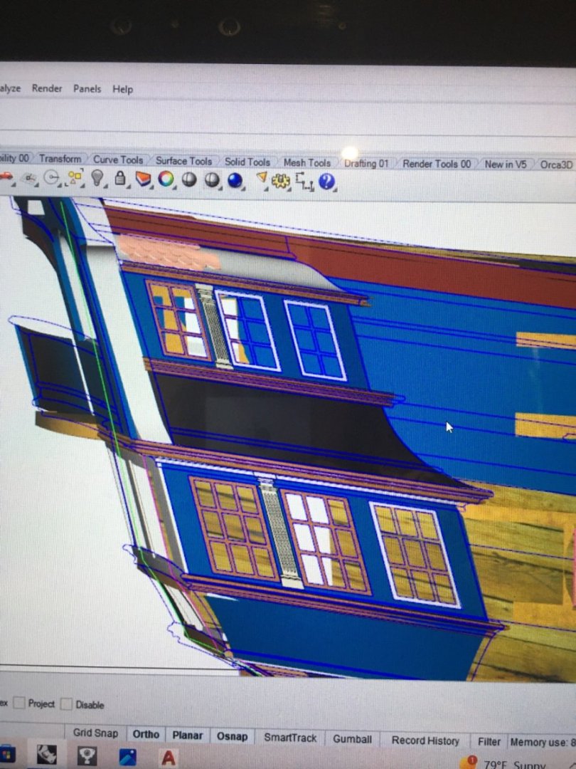
Hi Rob, I experienced the same thing with the QG door framing, in the end I landed somewhere between the framing drawing and the Portland outboard profile. Looking at my 3D model with the QG in place, it would be extremely difficult to spot an error or discrepancy through the window frame and QG structure.
-
Allan, I do have the Bristol Drawings but I’m curious to what hi res Portland drawings you have? I have Portland framing plan ZAZ1719 and Portland inboard profile ZAZ1720, these the ones you are referring to? I also have a very high res drawing of Portland profile drawing and body plan ZAZ718. ZAZ1718 has Portland written specifically on the drawing near the mast particulars. It is dated 10th January, 1766 and it matches up very well with the marshal painting of the Portland contemporary model.
-
There are several differences between the class, as I’ve been designing Portland, the 1st in class, I’ve found several differences between her and Bristol, of course Bristol being the 2nd in class. Length of poop deck and cabins being one major change. Portland shows higher Taft rail which may also contribute to the higher frames you mention. The framing drawing is dated 1776 and although it does mention Europa, Jupiter, Hannibal and Adamant, I believe this is possibly an as built drawing or slight revision as it’s labeled as a copy that was sent out for those listed ships to be built. It did overlay well on my profile drawing of Portland dated 1766.
-
Or the divorce proceedings. Lol
-
I coulda contributed some half built models lol. Rules for rules and more rules on top of that! hope to see more, exciting project for sure.
-
Can you post pics of the workshop set you’re making? Are we going to see Winnie on the big screen?
-
Looks good Greg, glad to see you’re back at it!
-
It’s my understanding volume 3 will cover the 4ths, 5ths and whatever else is left.
-
Very nice Mike! Your frame work looks immaculate.
-
From model ships to movie star! Well done Chuck! Congratulations! When shall we expect to see your film debut? Very exciting! Does Ed actually build model ships or just his character?
-
Bristol 1775 - from Warship to Prison Hulk
scrubbyj427 replied to westwood's topic in Nautical/Naval History
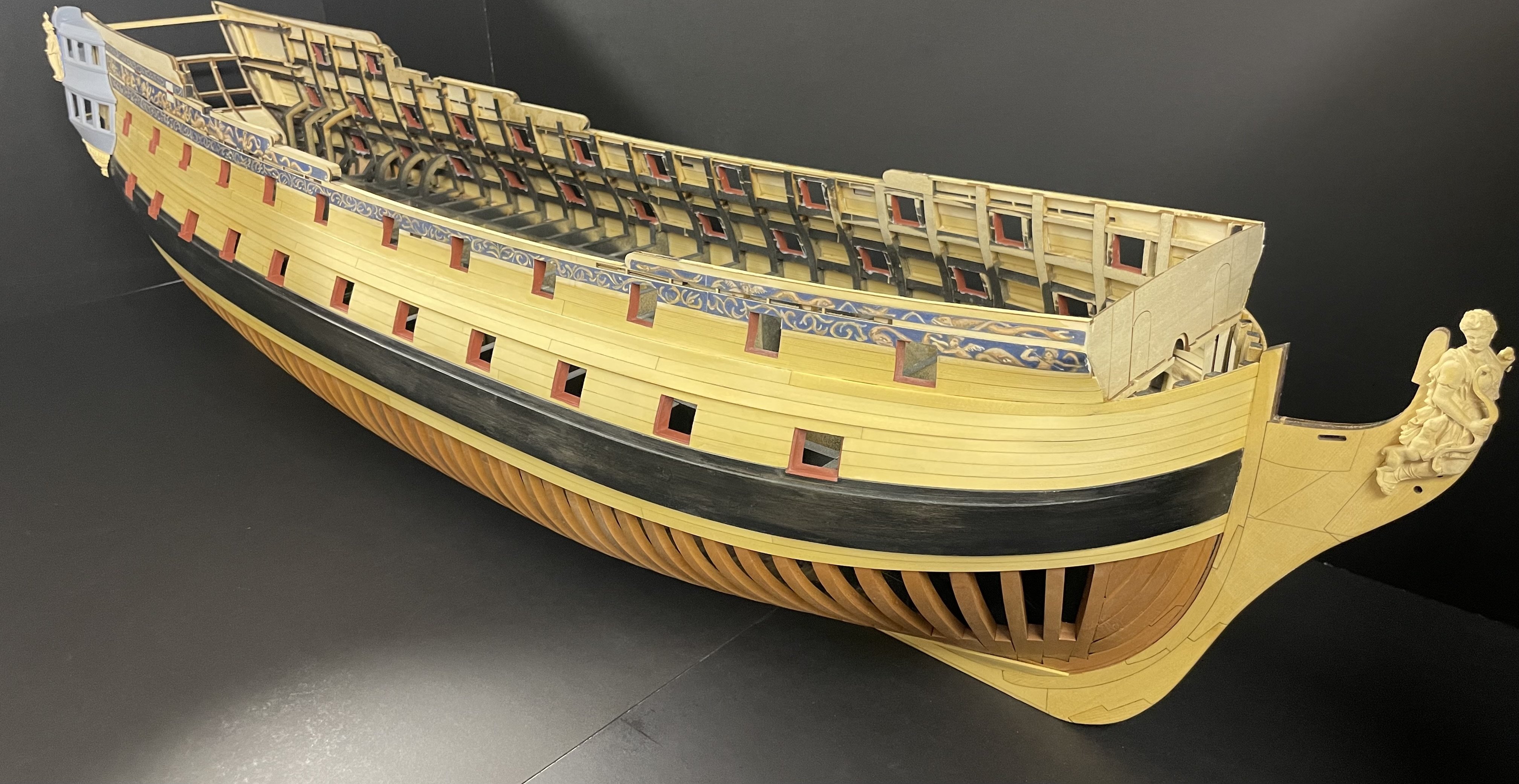
If anyone is interested in building Portland, Bristols older sister and the lead of class, I will be releasing a kit at 1:48 scale, sometime in the next year or two. The prototype build is underway…slowly. -
Bristol 1775 - from Warship to Prison Hulk
scrubbyj427 replied to westwood's topic in Nautical/Naval History
Thanks for posting Dusan, That is very cool, I wish we could see more of the Bristol model. I will have to try on my computer. -
Nice to see you back at it Fred, she’s looking really nice. You may want To check the angle of your bollard Timbers or perhaps it’s the photos that could throwing me off. The mill work looks nice either way though. JJ
-
That looks awesome!
-
Stunning model and display. Well done!
-
Beautiful work!
-
Siggi, I’ve never seen this method, that makes sense. Simple and effective. Well done!
-
This is just awful news. Very sorry to hear, 64 is just too young. Thank you for all you have contributed to our hobby, RIP Jim.
-
Welcome back! Your lower deck structure is looking really good.
-
Thank you Allan, I’m still experimenting with the lines as well as a partially framed version. Materials are hard to obtain right now.


