HOLIDAY DONATION DRIVE - SUPPORT MSW - DO YOUR PART TO KEEP THIS GREAT FORUM GOING! (Only 36 donations so far out of 49,000 members - C'mon guys!)
×
scrubbyj427
-
Posts
1,668 -
Joined
-
Last visited
Content Type
Profiles
Forums
Gallery
Events
Everything posted by scrubbyj427
-
 Very nicely done! Displayed very well, looking forward to seeing the complete display.
 -
Great work Frank! Very precise as usual.
-
6-pounder, Royal Navy cannon barrel - George III era
scrubbyj427 replied to Gabek's topic in 3D-Printing and Laser-Cutting.
Looks really good. Nice work Gabe. -
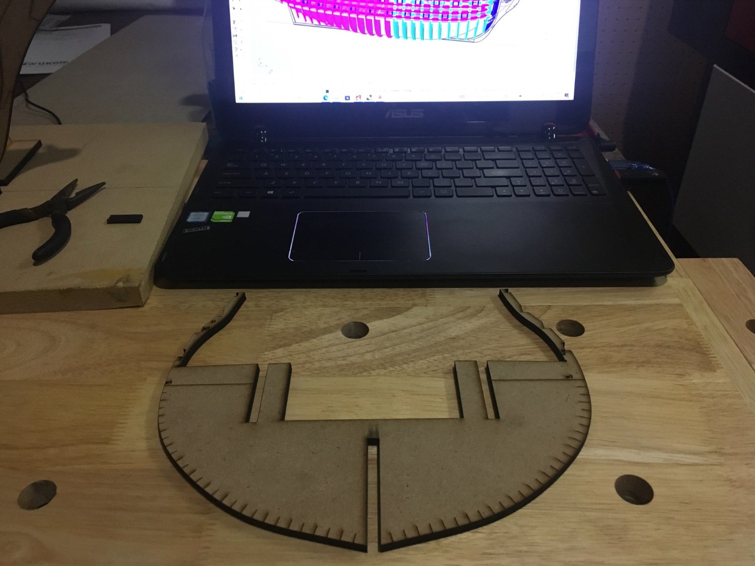
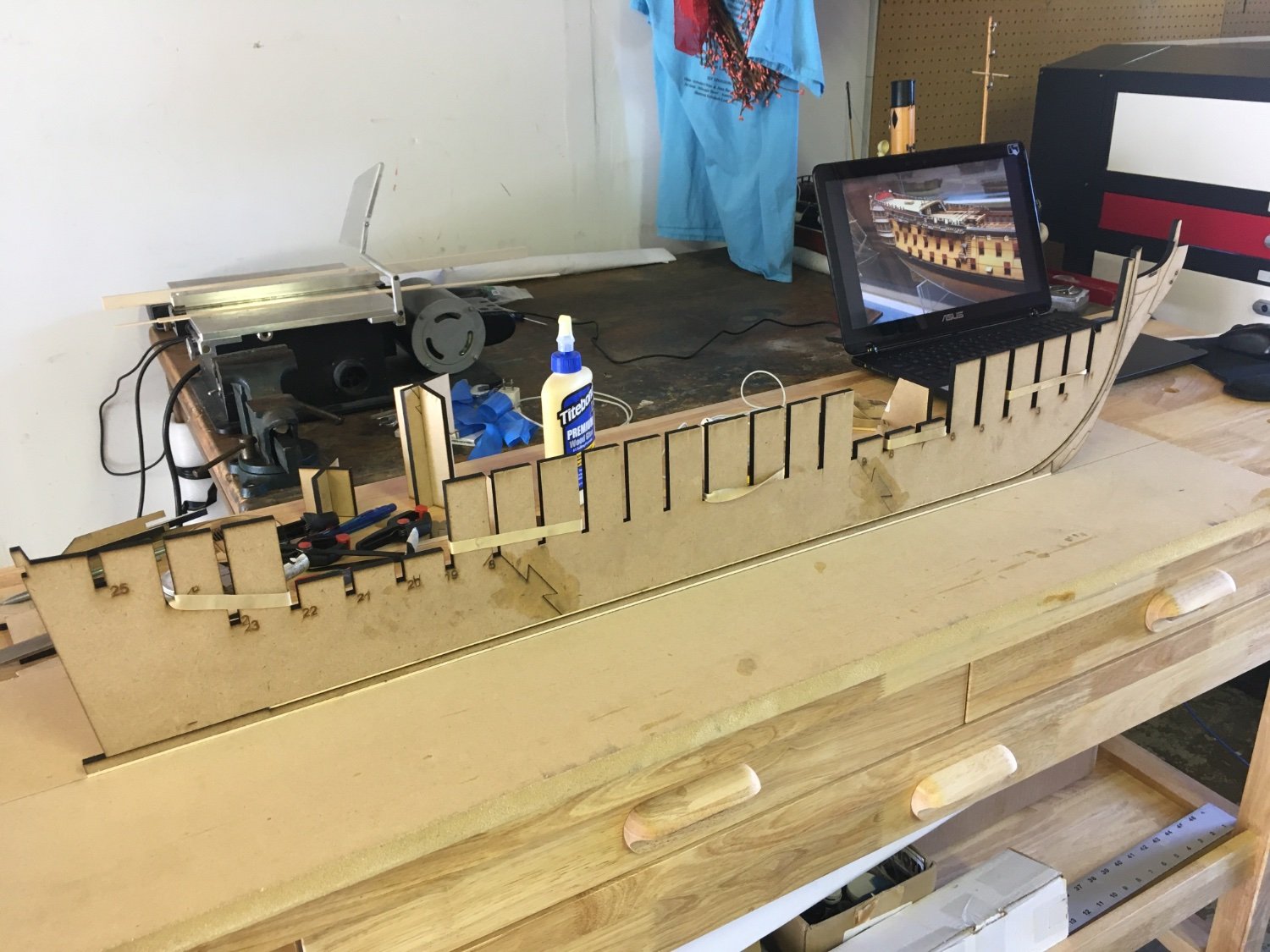
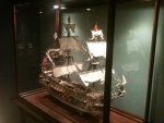
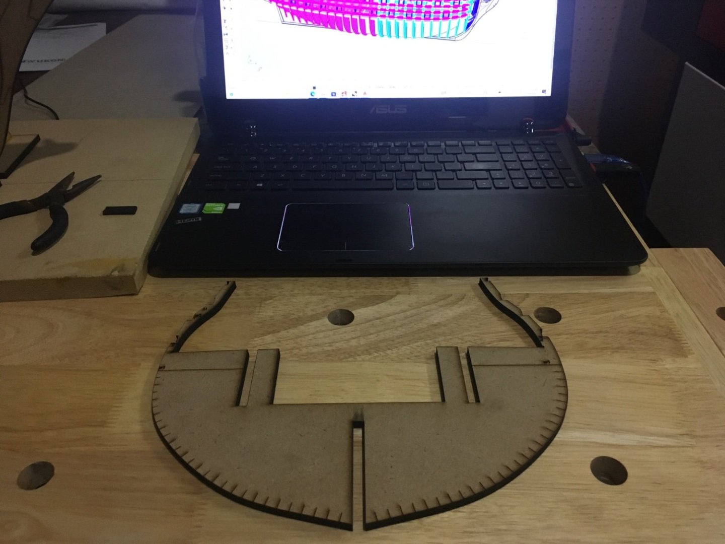
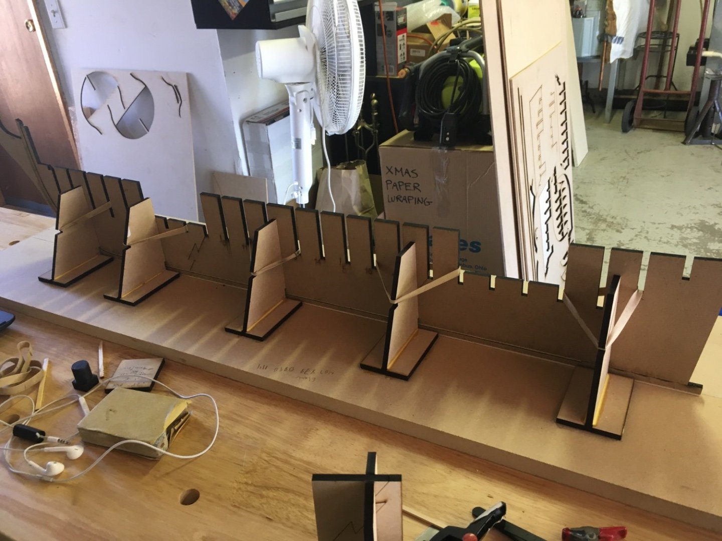
Small update: So I’ve had very little progress as I’m experiencing some laser issues which is eating up a lot of material, so until I reach tech support and resolve the issue I’ve decided to postpone anymore attempts at cutting parts, especially AYC. But I’ve got a few bulkheads cut and I’m pleased with how they fit, establishing proper tolerances is challenging, I will find out how well it will go together when I get additional longitudinal structure installed. I hope to be up and running again next week and will make some progress updates. I have been experimenting with lining off the bulkheads for planking and so far the results look promising on the computer model, marks made on the bullheads are designed to accommodate required fairing. Both sets of wales as well as the deck elevations are also represented.
- 370 replies
-
- 16
-

-
Thanks Glenn. No more real boats For me, I’ve moved onto the cushier side of being land based, but based far away…from my laser machine. I’m currently stalled as my laser machine is having some issues following cutting instructions, so I’m a little disappointed in my production for this trip home. Hopefully I’ll be back up and running next week and will be able to cut all the structure and take it all back with me to build the prototype. 🤞
-
HMS SUSSEX by KarenM - FINISHED - 1:48
scrubbyj427 replied to KarenM's topic in - Build logs for subjects built 1501 - 1750
Incredible work! -
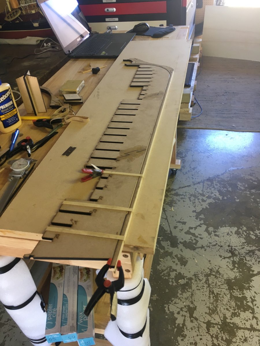
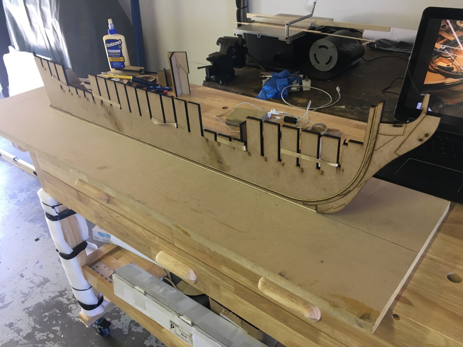
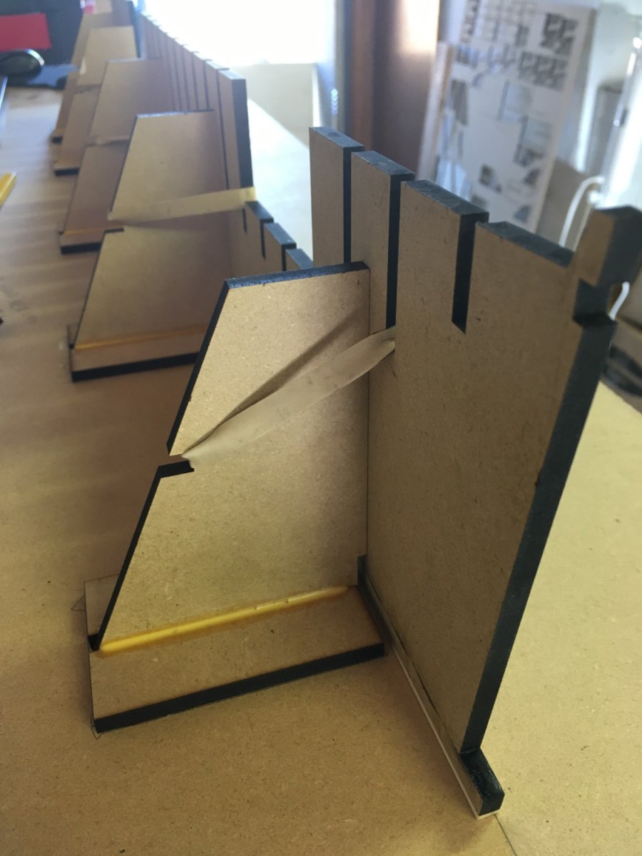
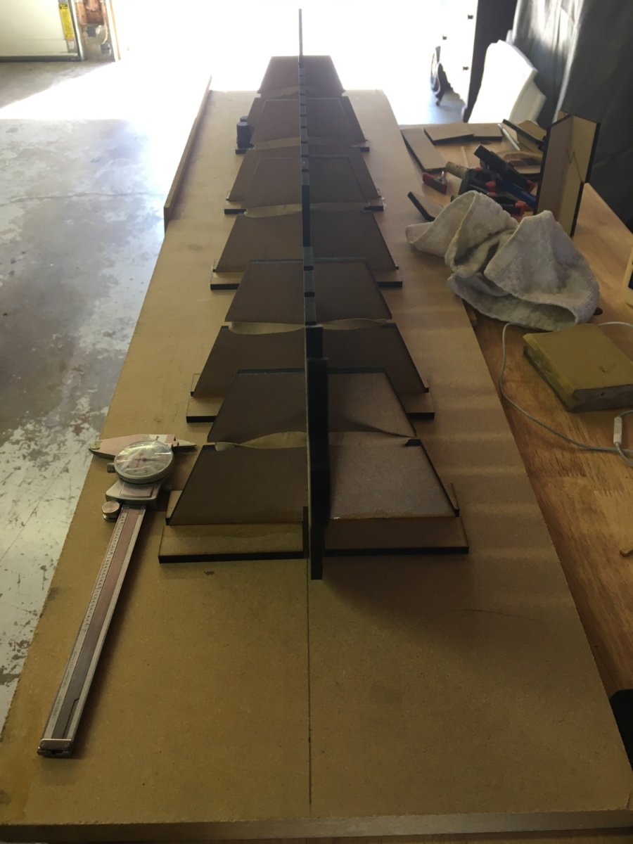
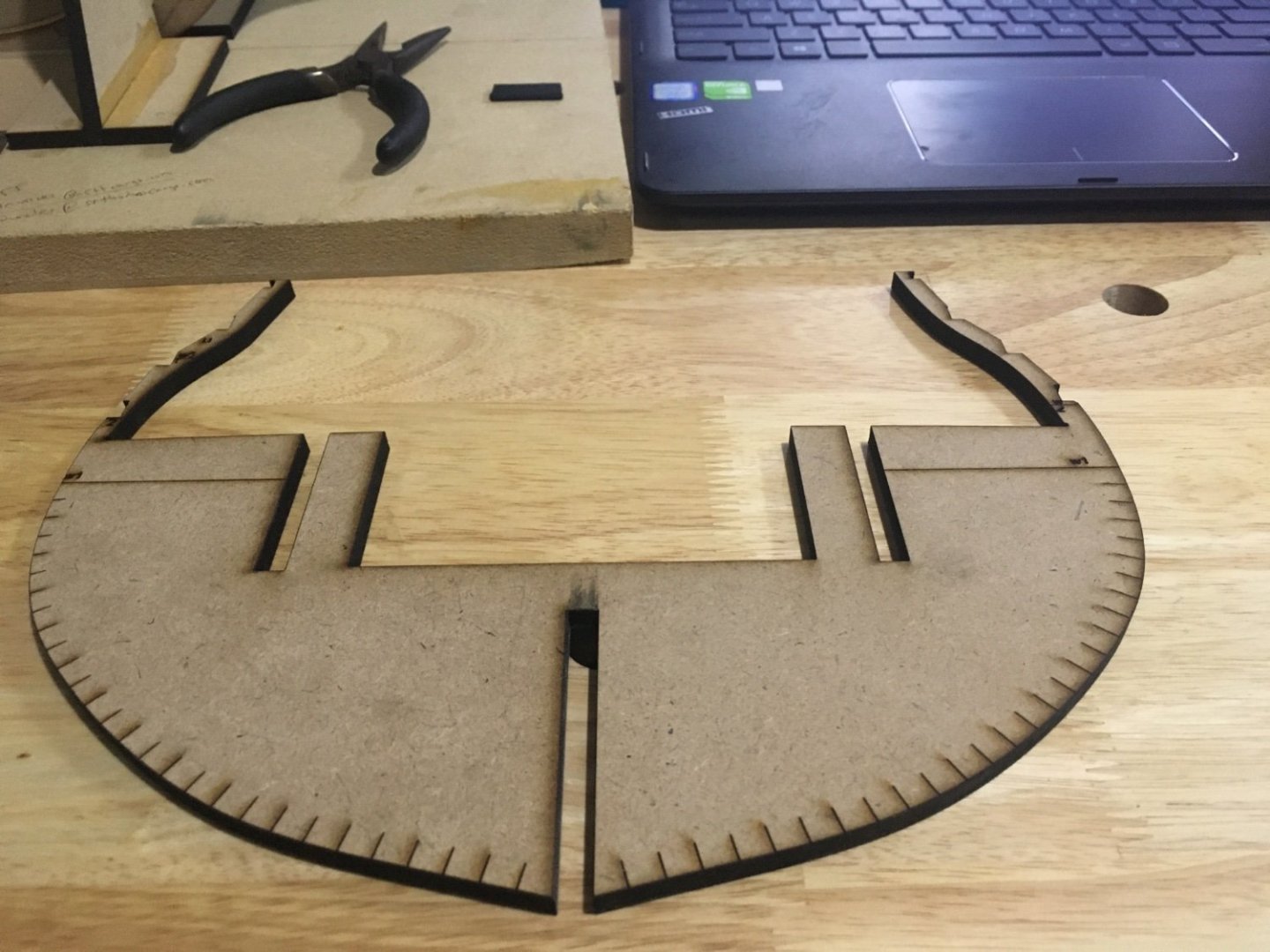
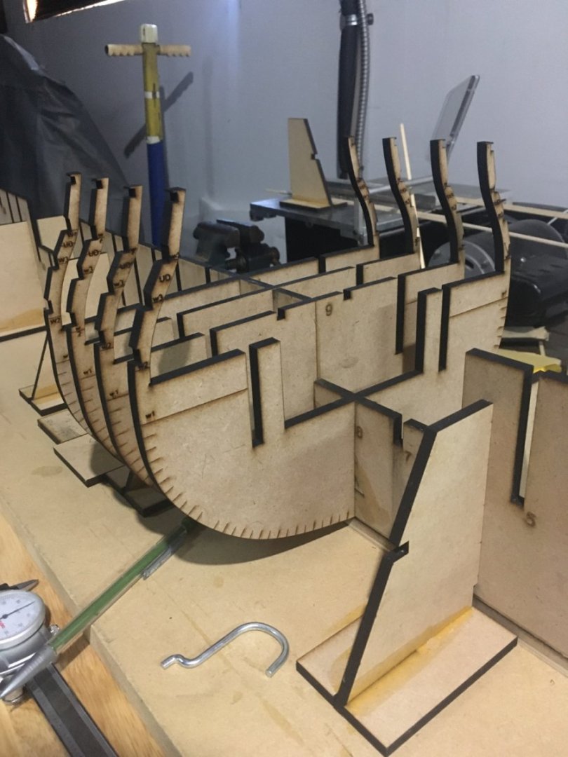
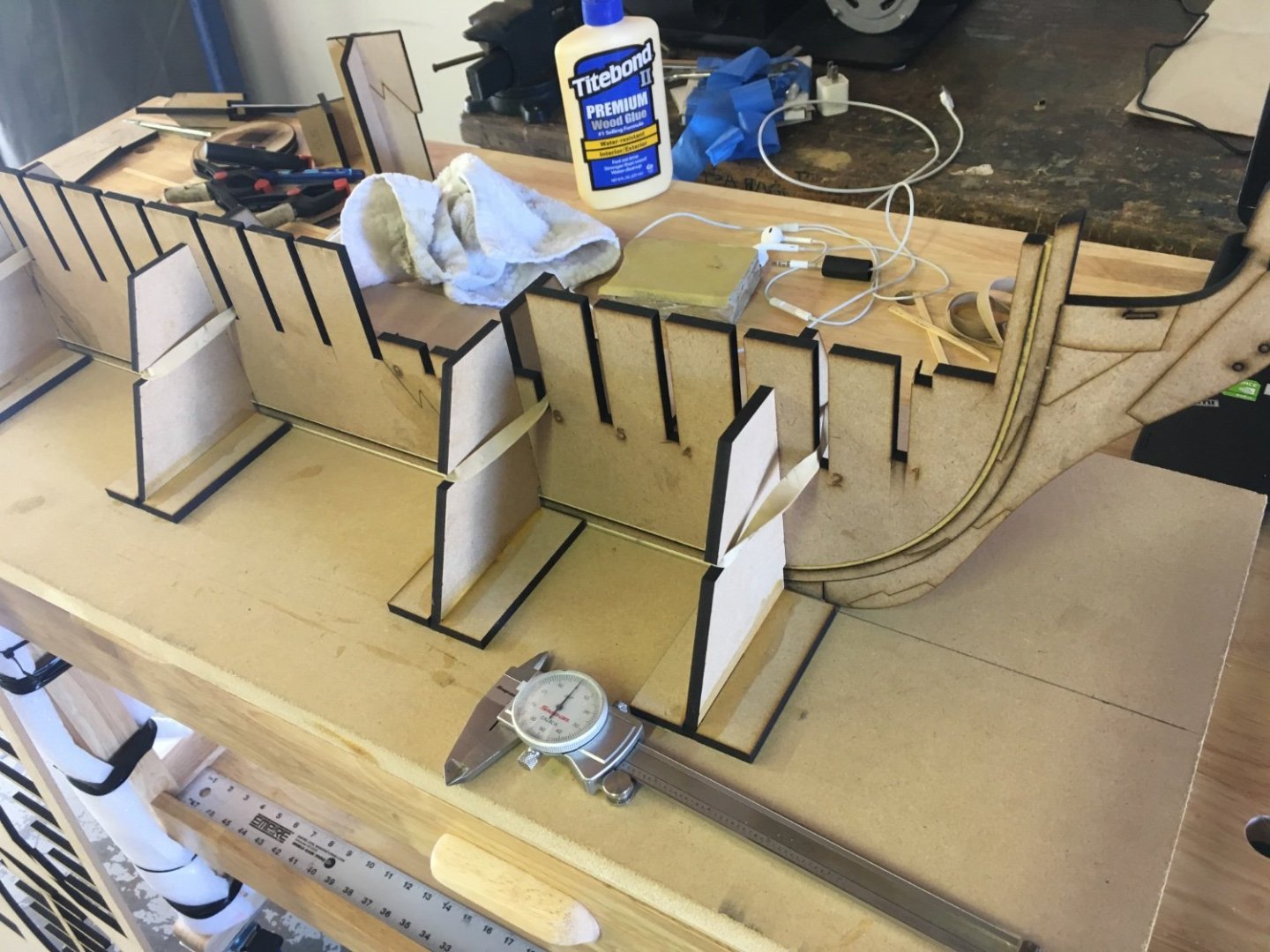
I’m working on assembling the first prototype, this one will be used primarily to test fit parts and it will only be built to accommodate the basic structure. Most all parts are MDF as it’s better place holder than more expensive woods. I’m hoping to get the bulkheads on tomorrow as well as the longitudinal structure, from there I will produce the longitudinal strakes for the gunport framing. More to follow soon.


- 370 replies
-
- 23
-
-
6-pounder, Royal Navy cannon barrel - George III era
scrubbyj427 replied to Gabek's topic in 3D-Printing and Laser-Cutting.
I’m definitely going to keep these in mind for down the road. -
Beautiful work Siggi! Everything looks perfect! Your Tiger build is my primary source of inspiration for my Portland model.
-
Great looking blocks! Wow!
-
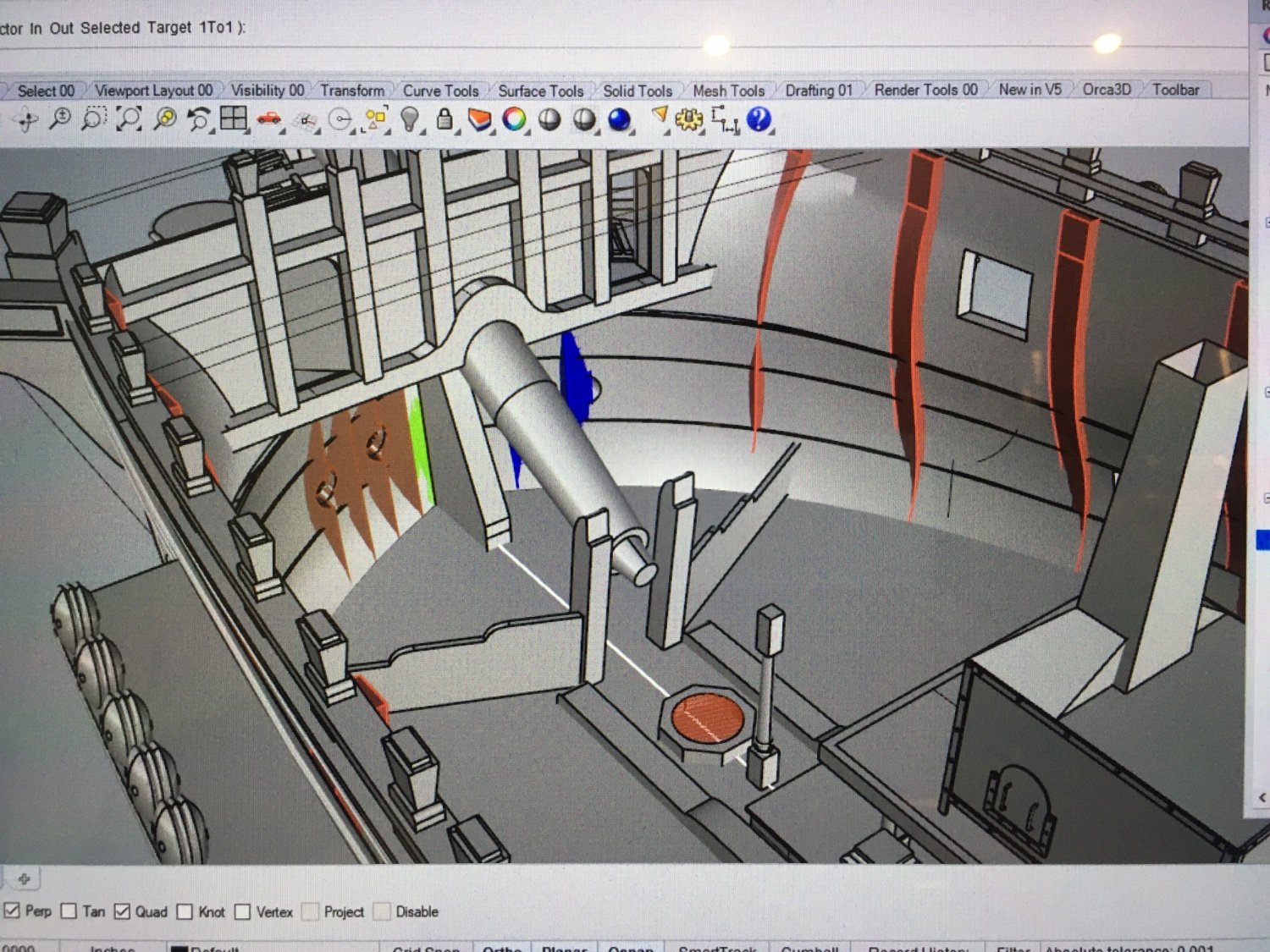
Hi Fred, Yes it is, it needs some revising as I’ve learned more since I modeled the bowsprit, but you get the idea. Winnie should be very similar, I’m sure Chuck knows way more. Im flying home to begin cutting the first part of the model. I’ll be assembling two prototypes and will be posting updates very soon. Stay tuned!
-
Beautiful work Fred! Excellent idea with the balsa and your fairing looks really good from here. As Chuck Pointed out early on, it’s very important to get those frames all faired up to the right thickness. This should be a great build. You should be able to contain your bowsprit in the structure that comes down from the bitts, this should allow you to partially plank the forecastle deck. i have not looked at the drawings for Winnie but I’m betting it’s very similar to a 4th rate. There would obviously be structure where the end of the bowsprit would fit into.

-
HMS SUSSEX by KarenM - FINISHED - 1:48
scrubbyj427 replied to KarenM's topic in - Build logs for subjects built 1501 - 1750
Outstanding! What a beautiful model! This is just incredible work you have done. Congratulations! -
Very nicely done! The table and charts are a wonderful addition!
- 587 replies
-
- 3
-

-
-
- Indefatigable
- Vanguard Models
- (and 1 more)
-
Costs are pretty much the same either way. AYC will have more of a contemporary model look to it, depending on how you treat it, but some prefer the warmer brown tones of the cherry. I think both look great ( see Rusty’s build log).
-
I think the trumpeter 1/200 is probably the best on the market currently, yet still requires modifications if you want to be really accurate. But out of the box it appears to build into a nice Titanic. Olympic and Britannic are also possible with modifications.
-
Kit review 1:48 La Renommée section - CAF Model
scrubbyj427 replied to James H's topic in REVIEWS: Model kits
Very cool little kit! It looks like a very well designed project. Thanks for sharing! -
Looking very nice Glenn. Your railings look very good, tricky to install, no doubt. Well done. I didn’t even glue my QG roofs/rails on until the end of ch 11 I think! I knew they were doomed had i not.
- 840 replies
-
- 4
-
-
- winchelsea
- Syren Ship Model Company
- (and 1 more)
-
Outstanding! One of the best rigged models I’ve seen.
-
Welcome to the group! Looks like you’re off and running with a great start!
-
Incredible work! Congratulations on completing a beautiful model! It’s been a pleasure watching this build as well as a great learning experience. What’s next? JJ
- 589 replies
-
- 2
-
-
- le gros ventre
- cargo
- (and 1 more)
-
Wow! That is very impressive Matthias! Beautiful job!
-
I really like the idea of multiple models in one case and beautiful work on your previous display. Looking forward to seeing more.
-
Hi Alan, haha I hear what you’re saying. I was more referring to SE FL, I just moved out of Boynton and had to drive and deal with Miami and FTL traffic daily… that’s certainly nothing like what you describe! I always liked the west side much more. Miami/Lauderdale area is definitely a zoo, I lived in green acres at one point and traffic was backed up all the way up there. JJ
-
Aim SW then, or NW… south FL is an absolute zoo!