Search the Community
Showing results for tags 'finished'.
-
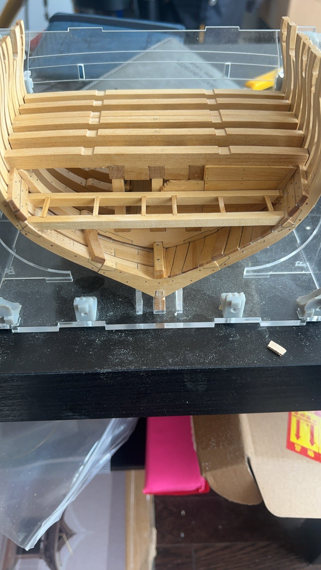
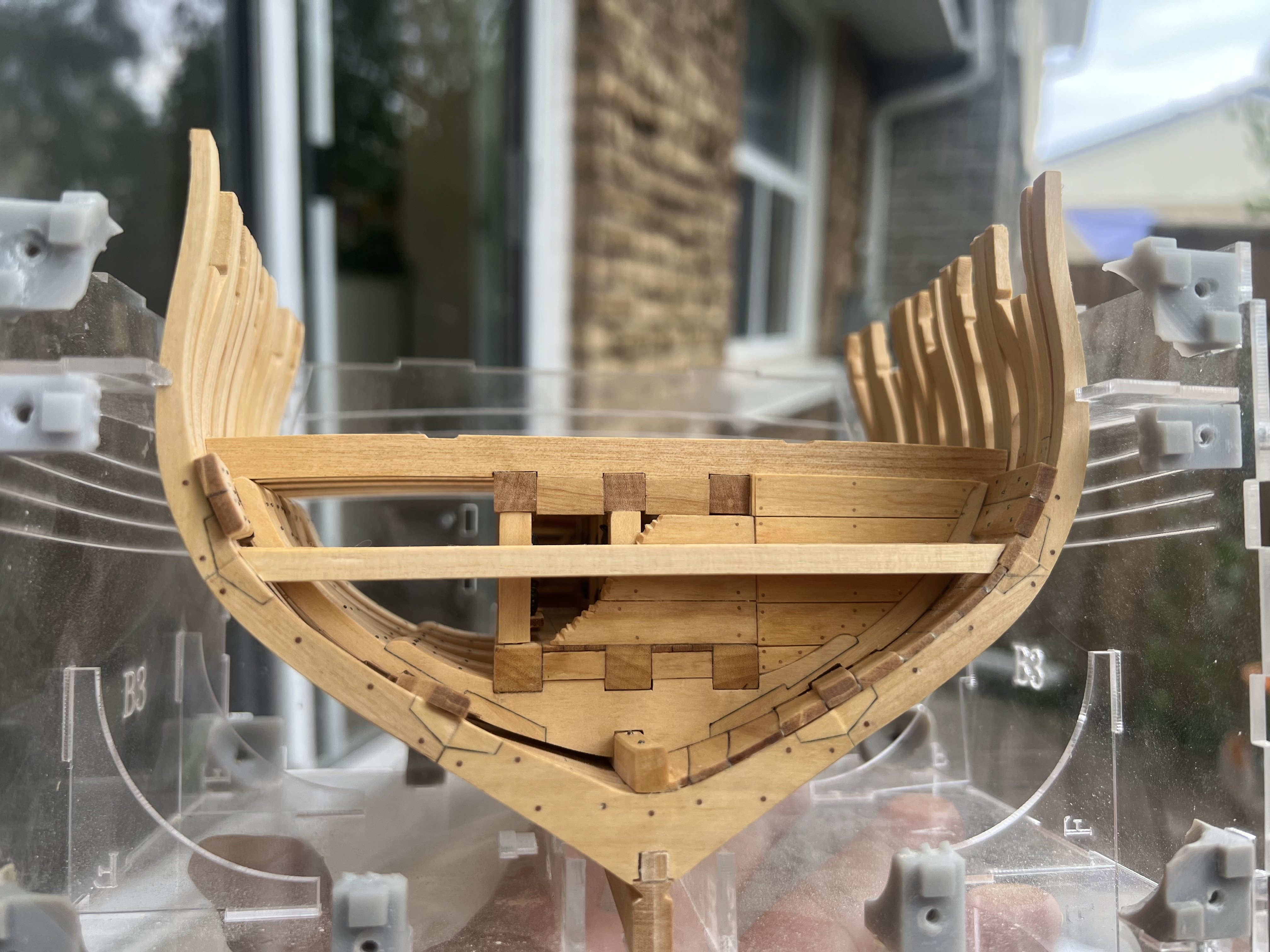
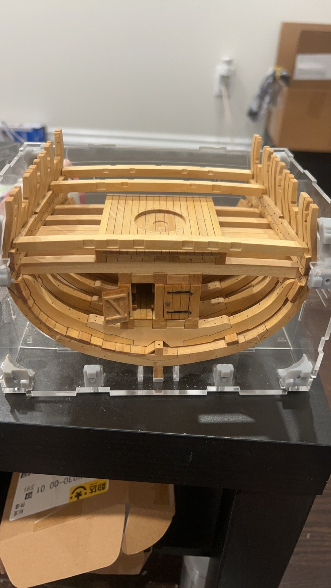
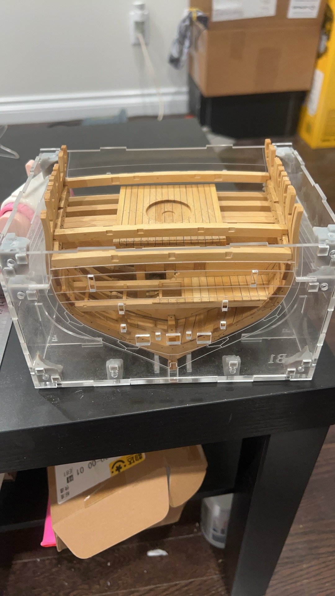
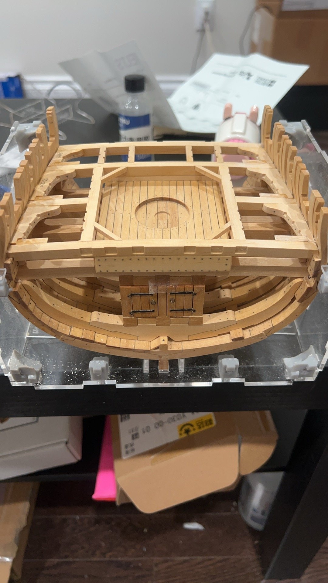
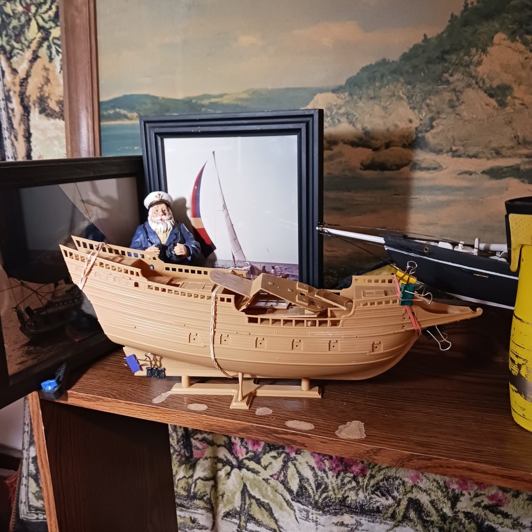
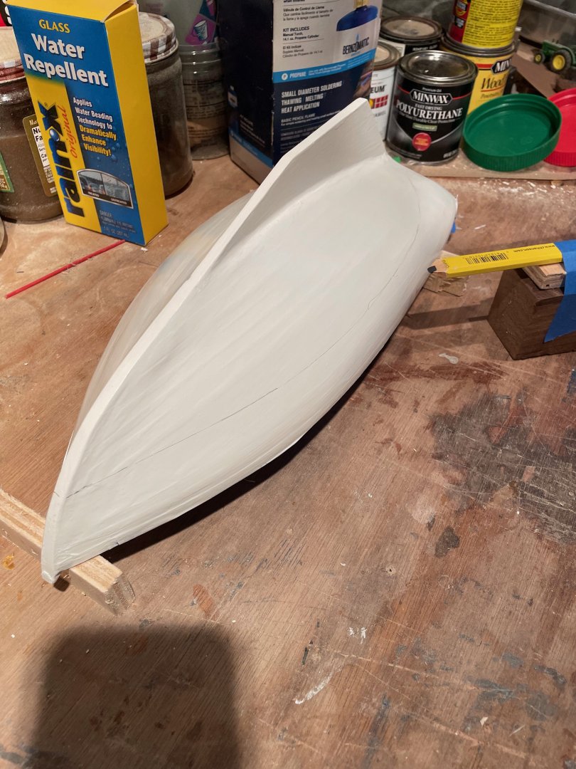
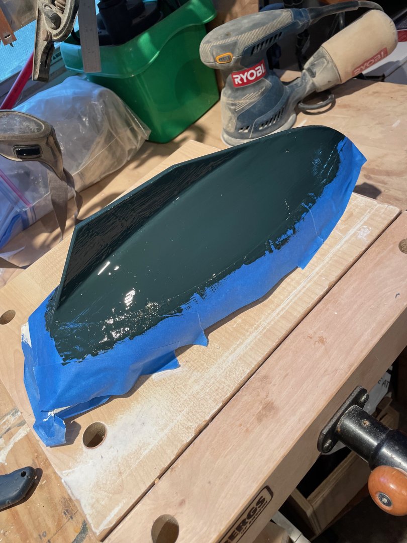
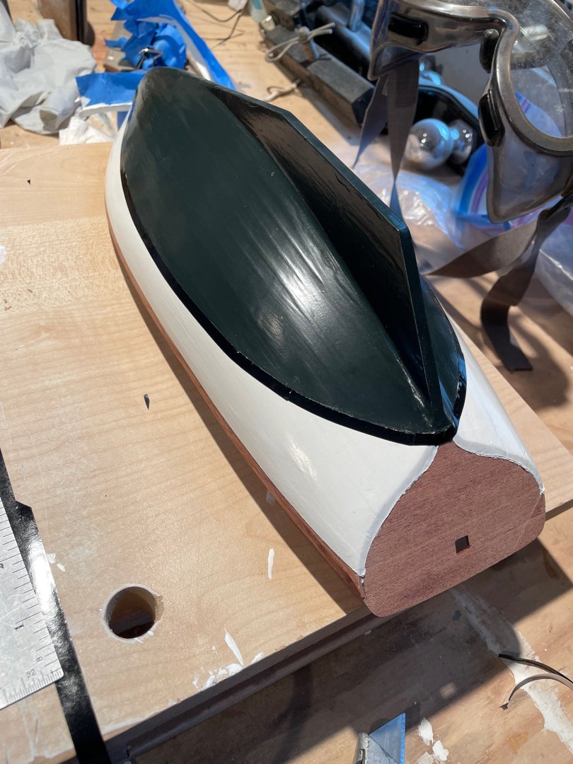
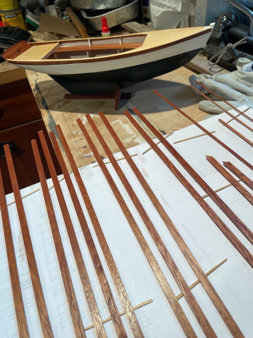
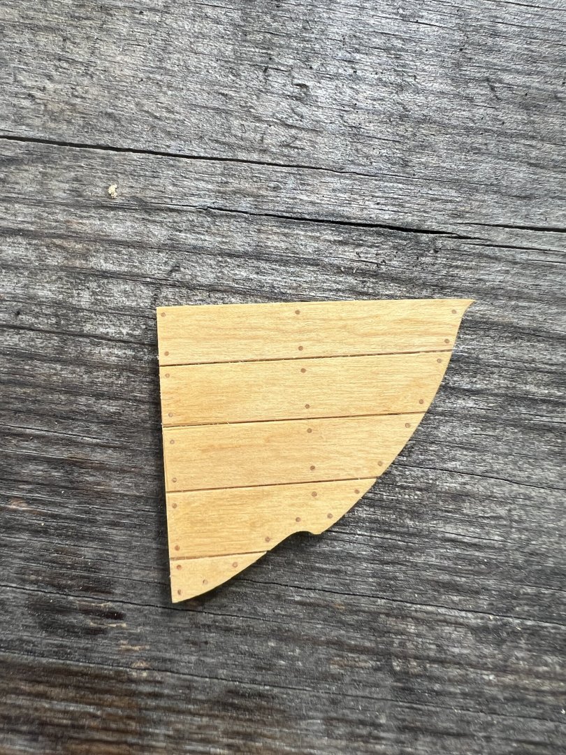
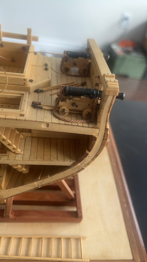
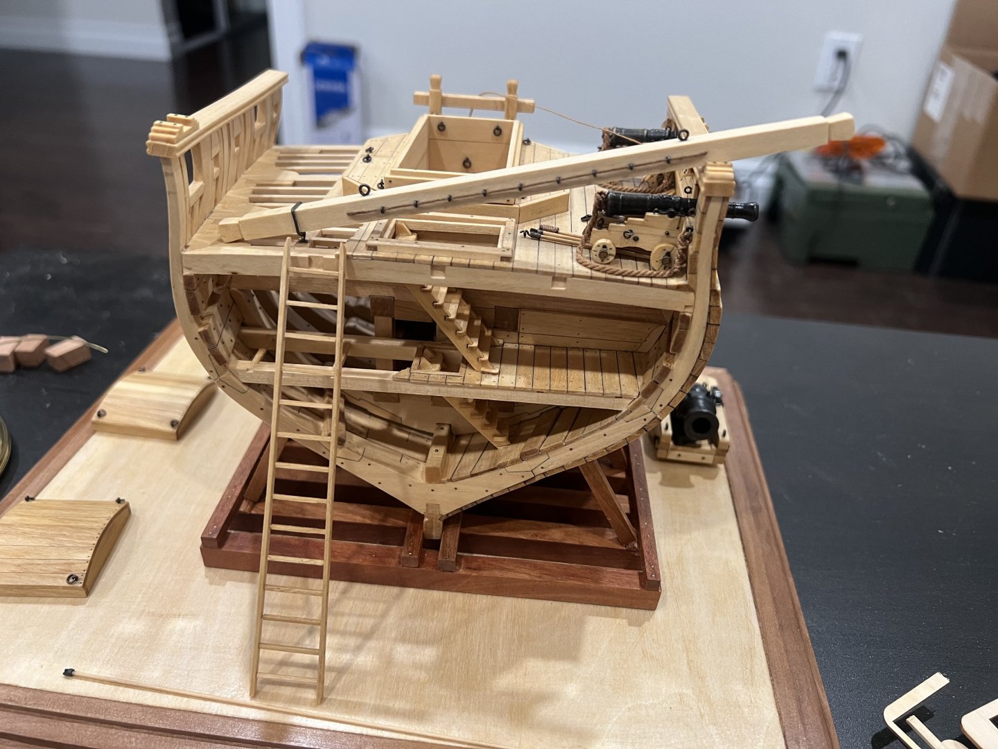
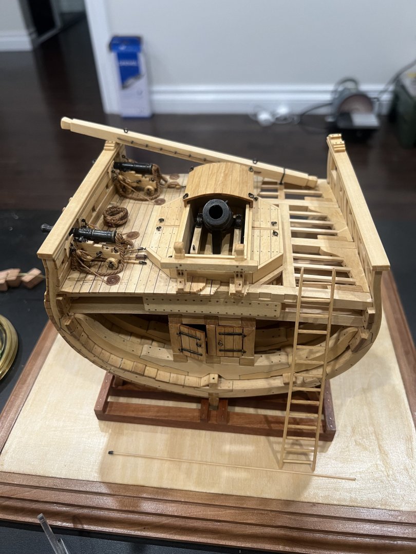
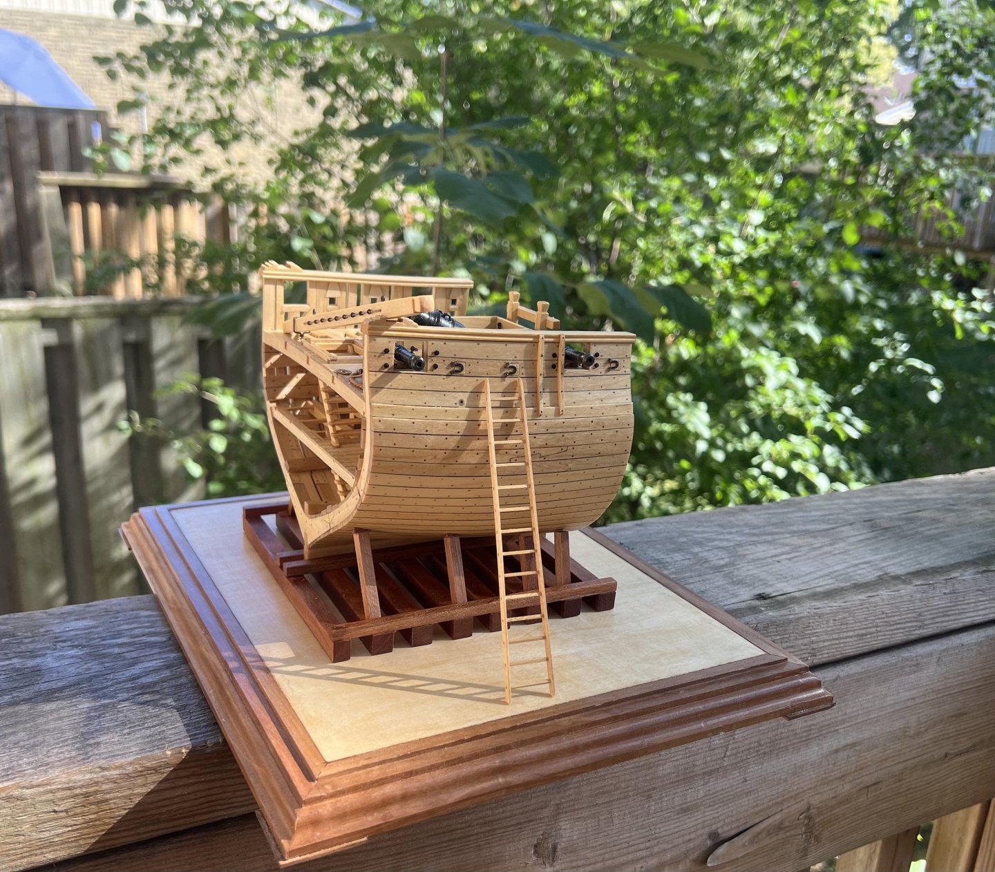
 Last year before my uncle passed away he had bought me a this model. He never had a chance to send it, my antie sent it to me earlier this year. I looked at it, and decided to put it in the stach , thinking some day maybe, I have been modeling for four years now, mainly wooden kits. And for the most part I have been having the time of my life, learning how too build and to tie rigging was and is the one of the most rewarding thingI did for myself. From my first attempt making the Santa Maria from Amati and my first posts I was hooked, @Louie da fly told me back then the my first planking looked like Roo Doo, , lol actually he said I should re do my planking, it was pretty bad lol. . He provide me with information about planking, and directed me to MSW Data base, and I have been trying to learn how to plank ever scence. Rigging is a different story, I love it, don't know why but ratlines are my favorite. Building and rigging is a lot of fun, if you have instructions, I love kit Building but bad instructions are the worst, that is why it will come as no" Surprise " which model I buy next. But in the mean time, the lack of instructions and the most enoying rigging diagrams I have ever seen, I find myself needing a break, and Building a plastic ship that look fairly easy to glue together and a very complicated paint job that will give me a lot of enjoyment learning how to paint it. I have been painting for over 50 years, but never an airbrush, and the model paint is some what different, and the brushes are very very small lol. I now have a brush that has only three hairs on it for painting eyes on figures 😳. So, Step one, the stand and hull. Next step two add a few more pieces, then start painting. Looking at the logs for this ship , and I have booked marked 4 so far I am sure there is more but I read slow. . Ok opening statement out of the way, time to learn about the Hind, one thing so far no one knows what' colors she was. Looking forward to learning about this ship,. Thanks for looking in, Bob M.
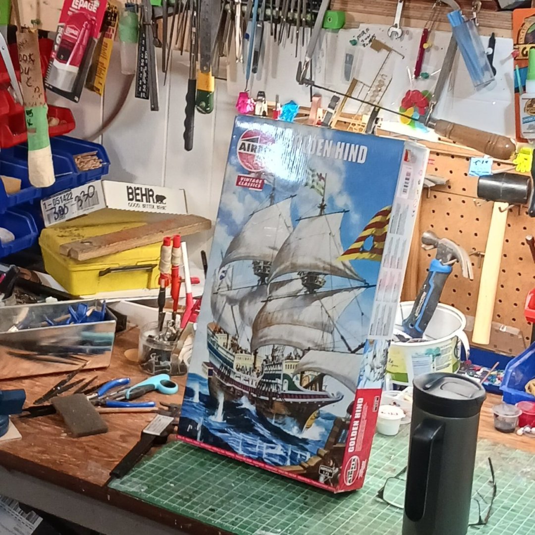
- 46 replies
-
- 8
-

-
- Golden Hind
- airfix
- (and 2 more)
-
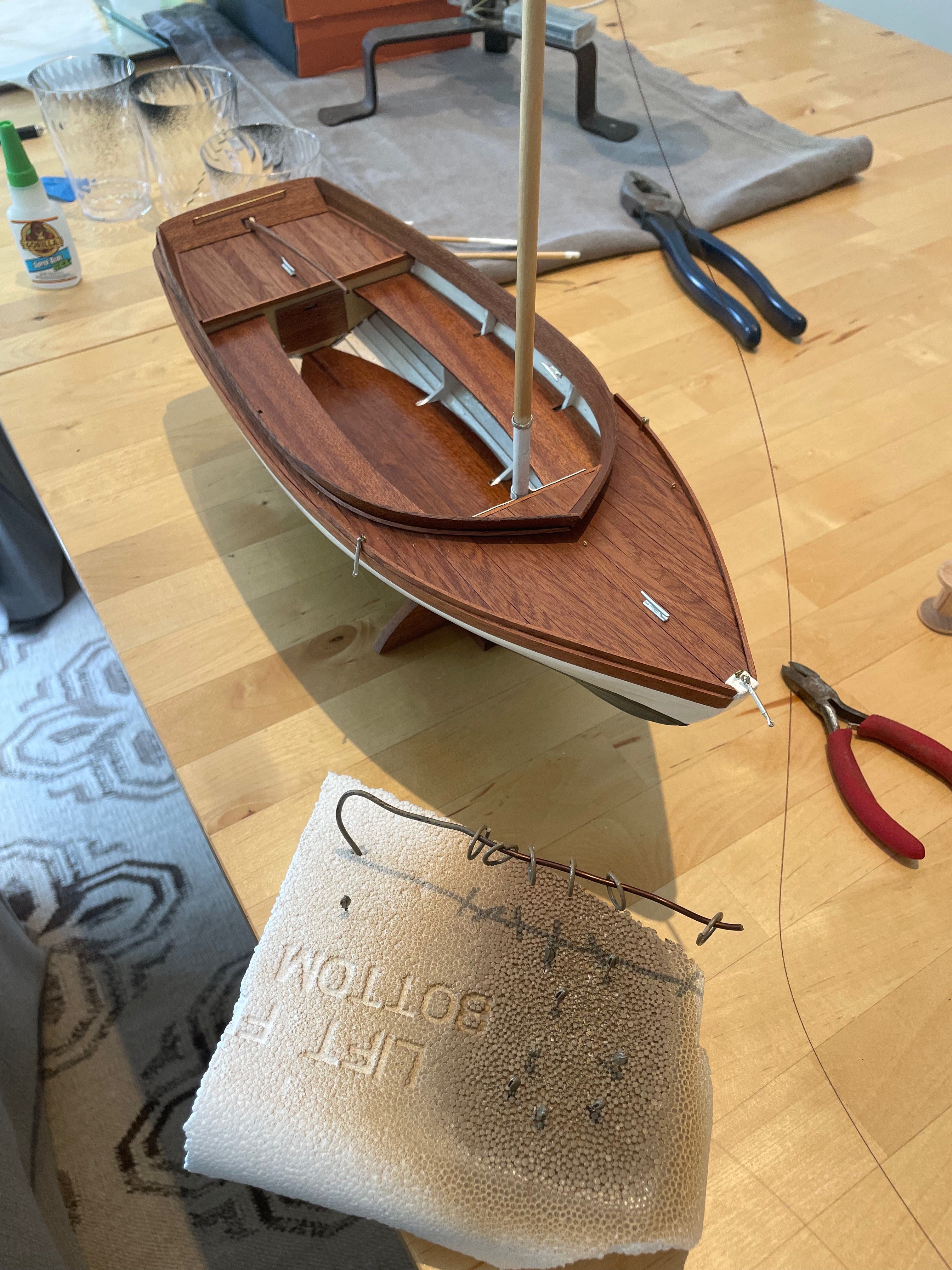
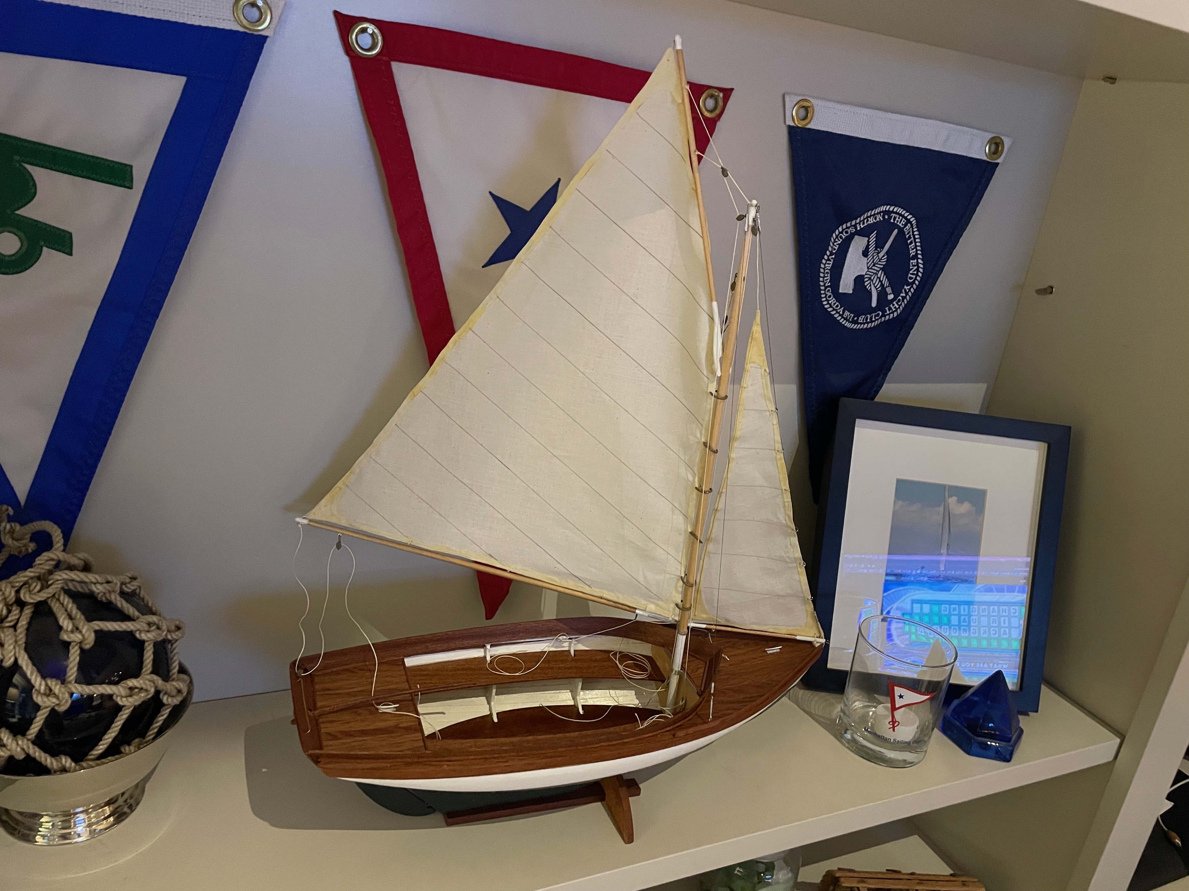
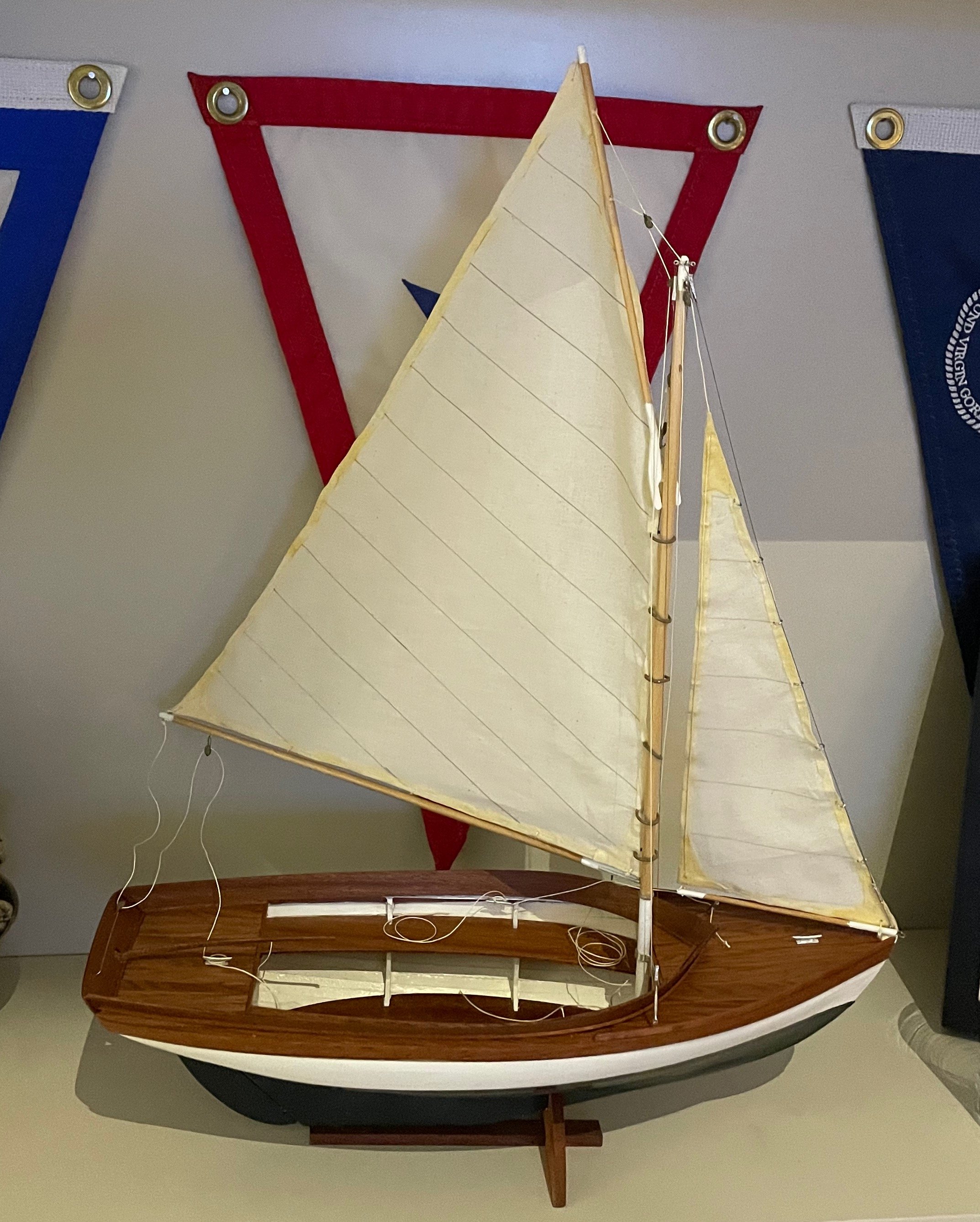
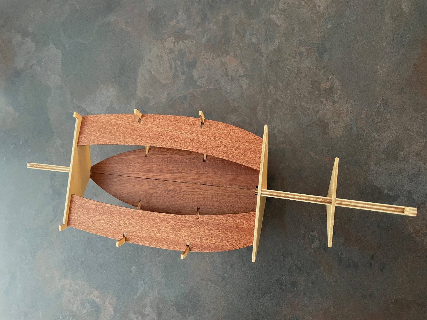
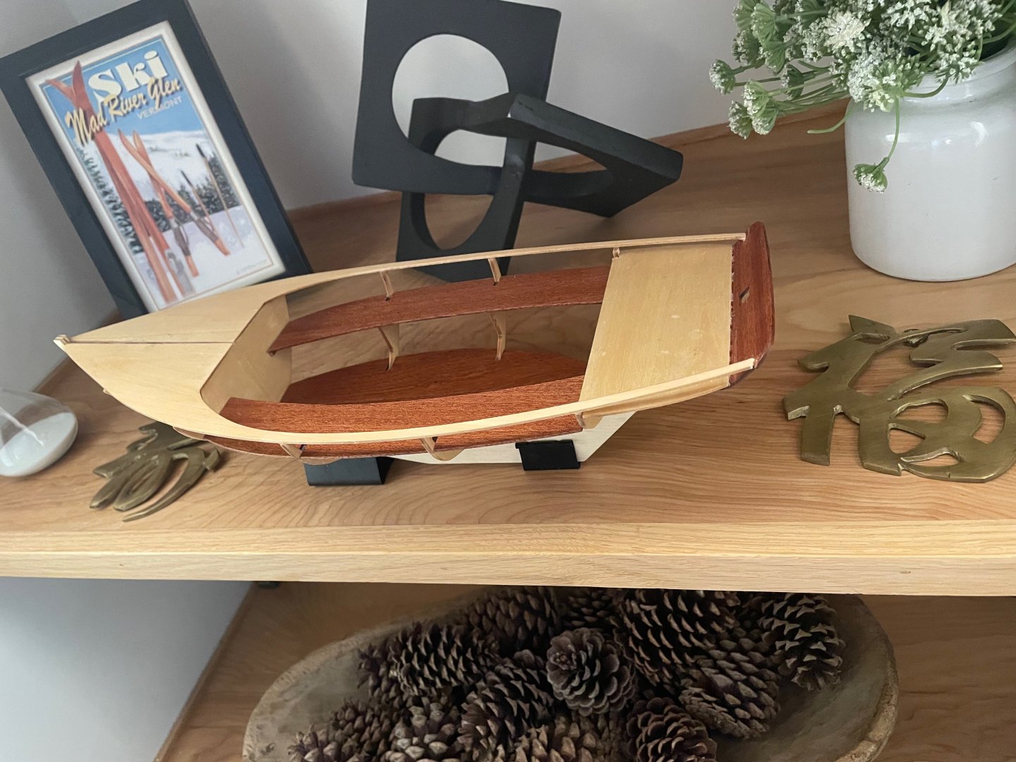
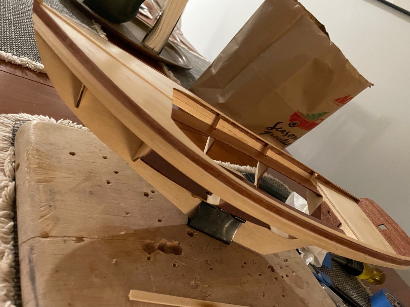
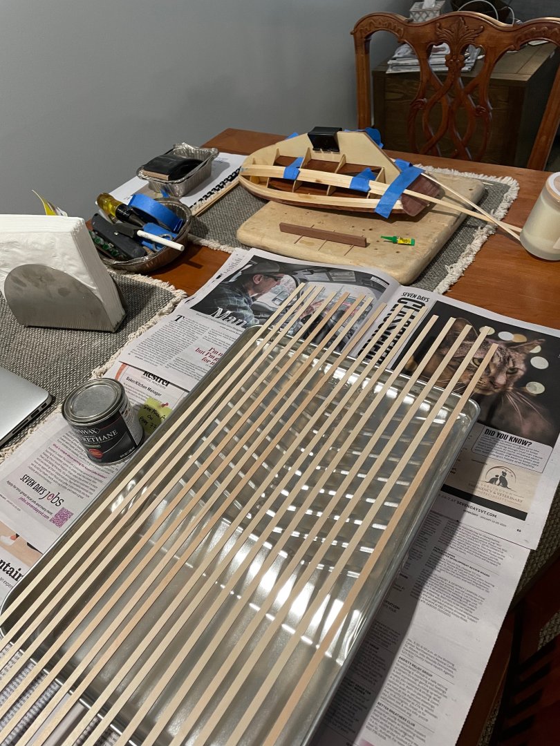
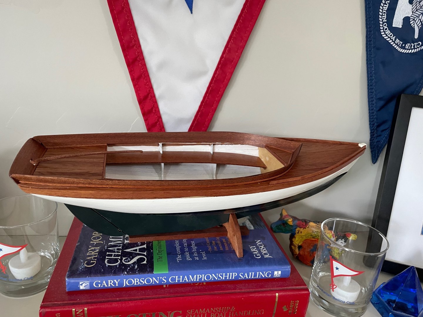
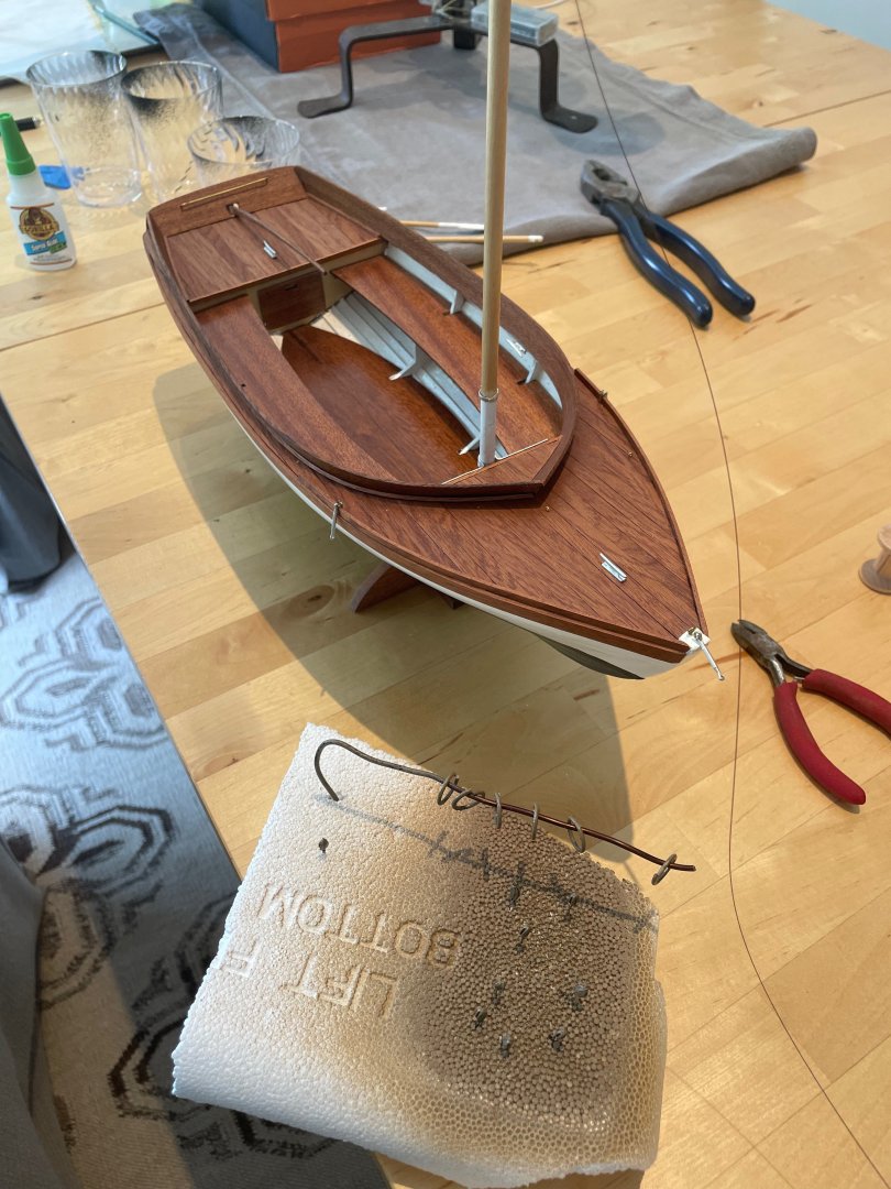
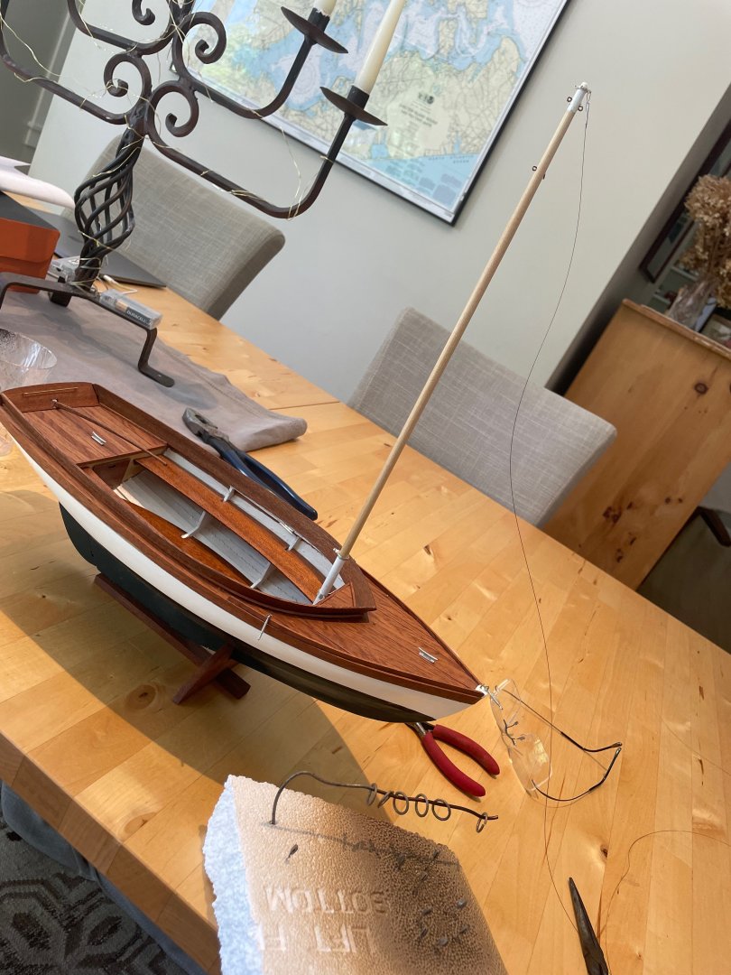
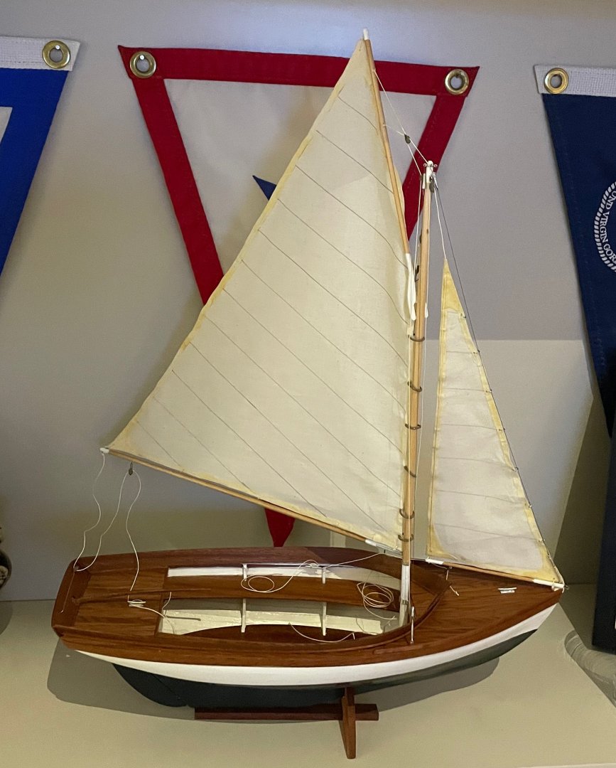
 Thanks to the community for prior build logs which helped me complete my hardest build to date. It was hard. It took way longer than I expected and it came out much better than I hoped. The kit was very high quality with good instructions. I wish the instructions had a link to this website which would have made things easier for me. I can see that this communities has a huge amount of experience and it shows! Thanks for the help. Here are some photos of the build. By the way, I wish I had a Herreshoff 12 1/2 myself. There is a nice size fleet near me on Shelter Island. Personally I have a Rhodes designed Wood Pussy. It sails great on the salt ponds near me but is lacking the size needed to be on the Peconic and is missing seats like the Herreshoff has. Thanks, Rob


- 2 replies
-
- 7
-
-
- Herreshoff 12 1/2
- BlueJacket Shipcrafters
- (and 1 more)
-
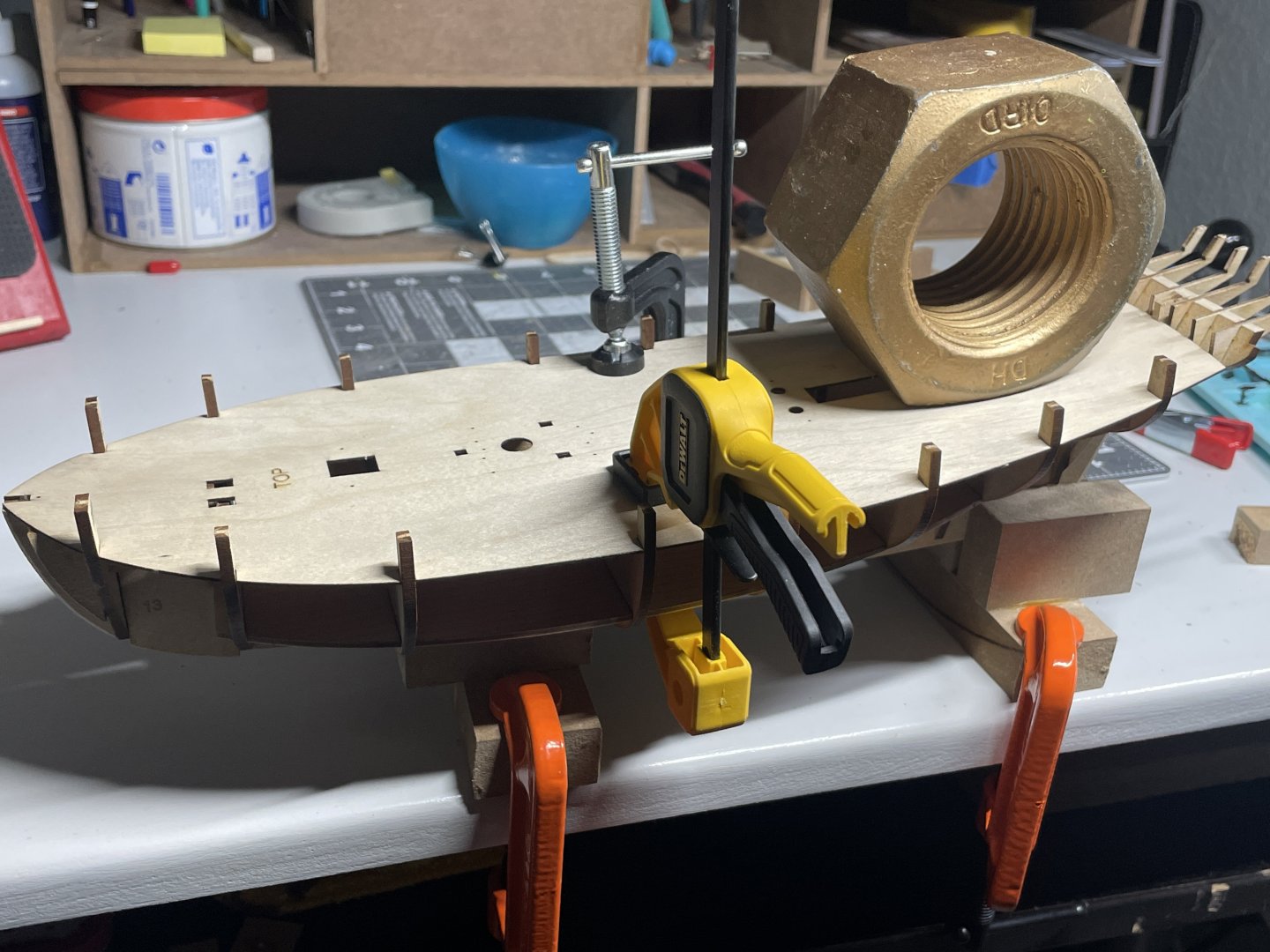
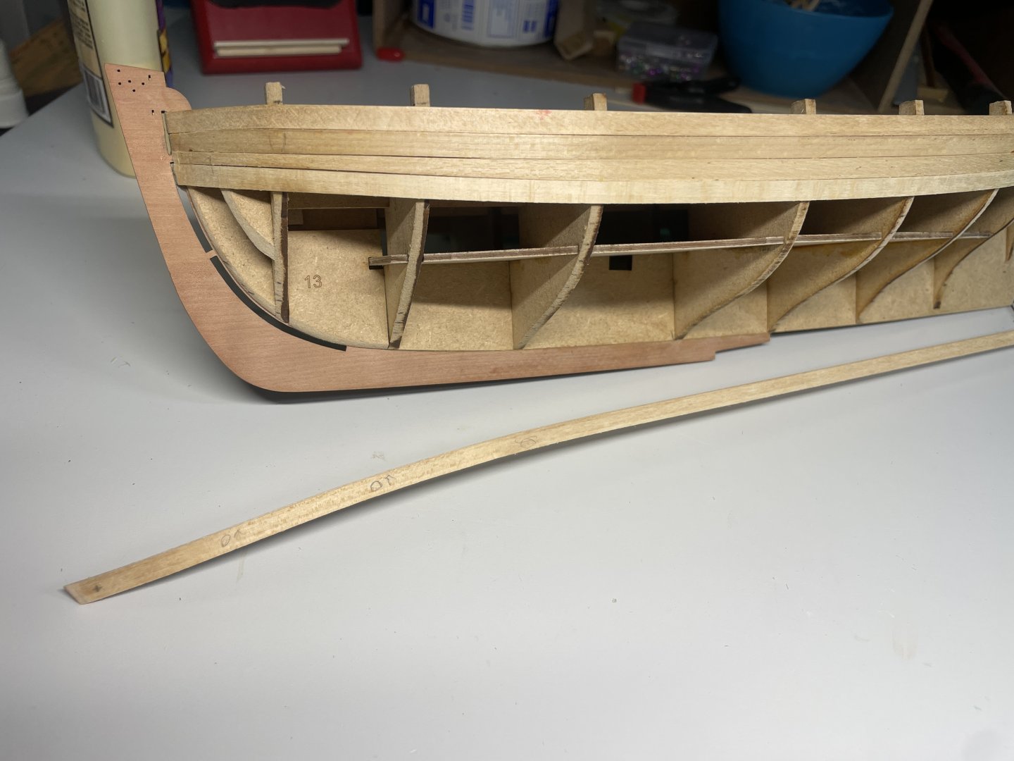
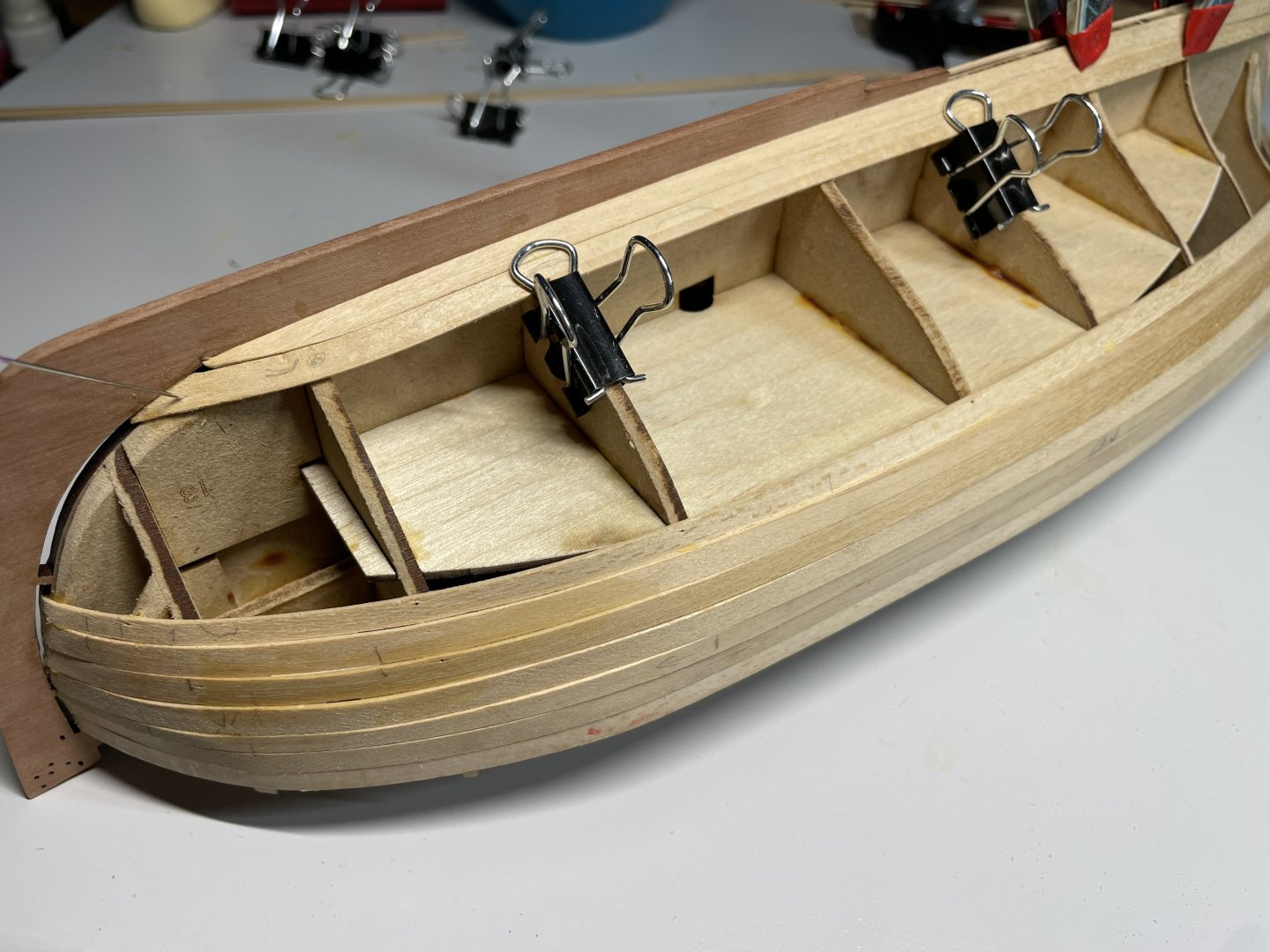
 Hello - Have decided to make another Fishing Boat. So here's the start. Regards Doug
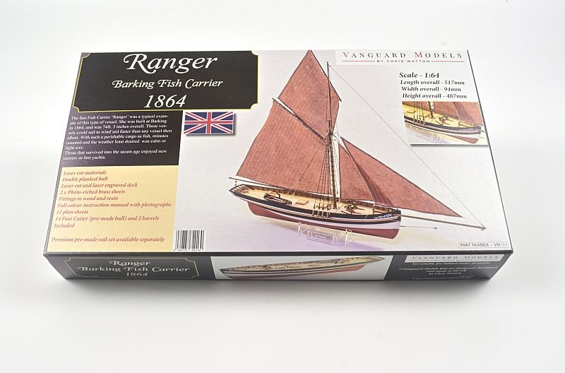
- 18 replies
-
- 6
-
-
- Ranger
- Vanguard Models
- (and 1 more)
-
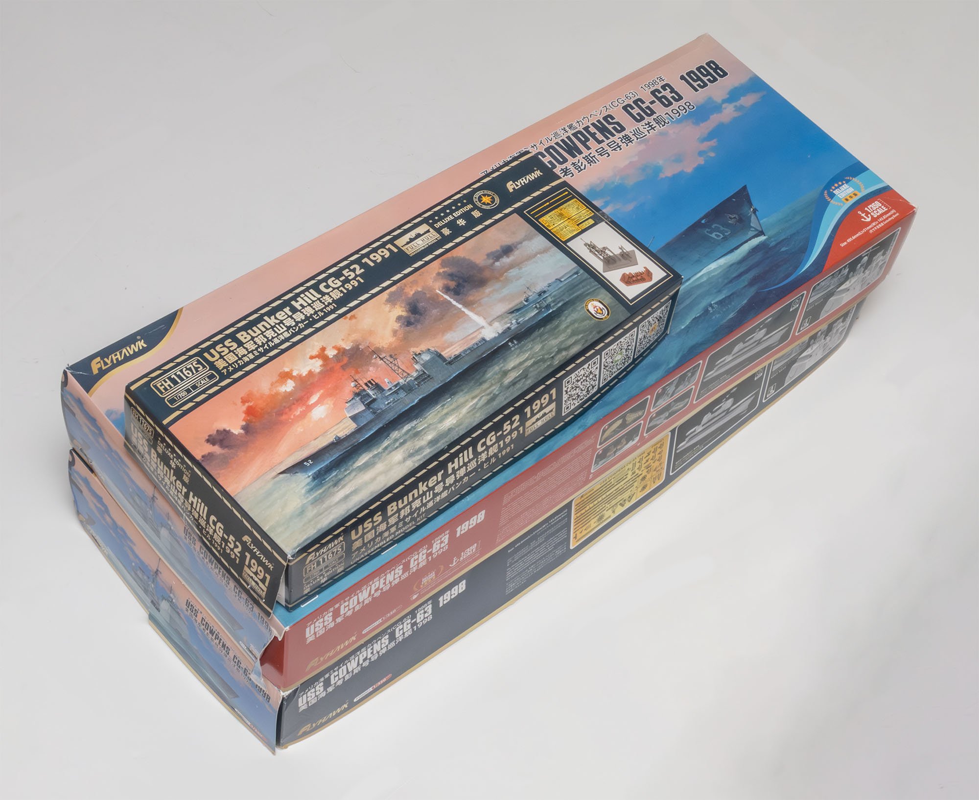
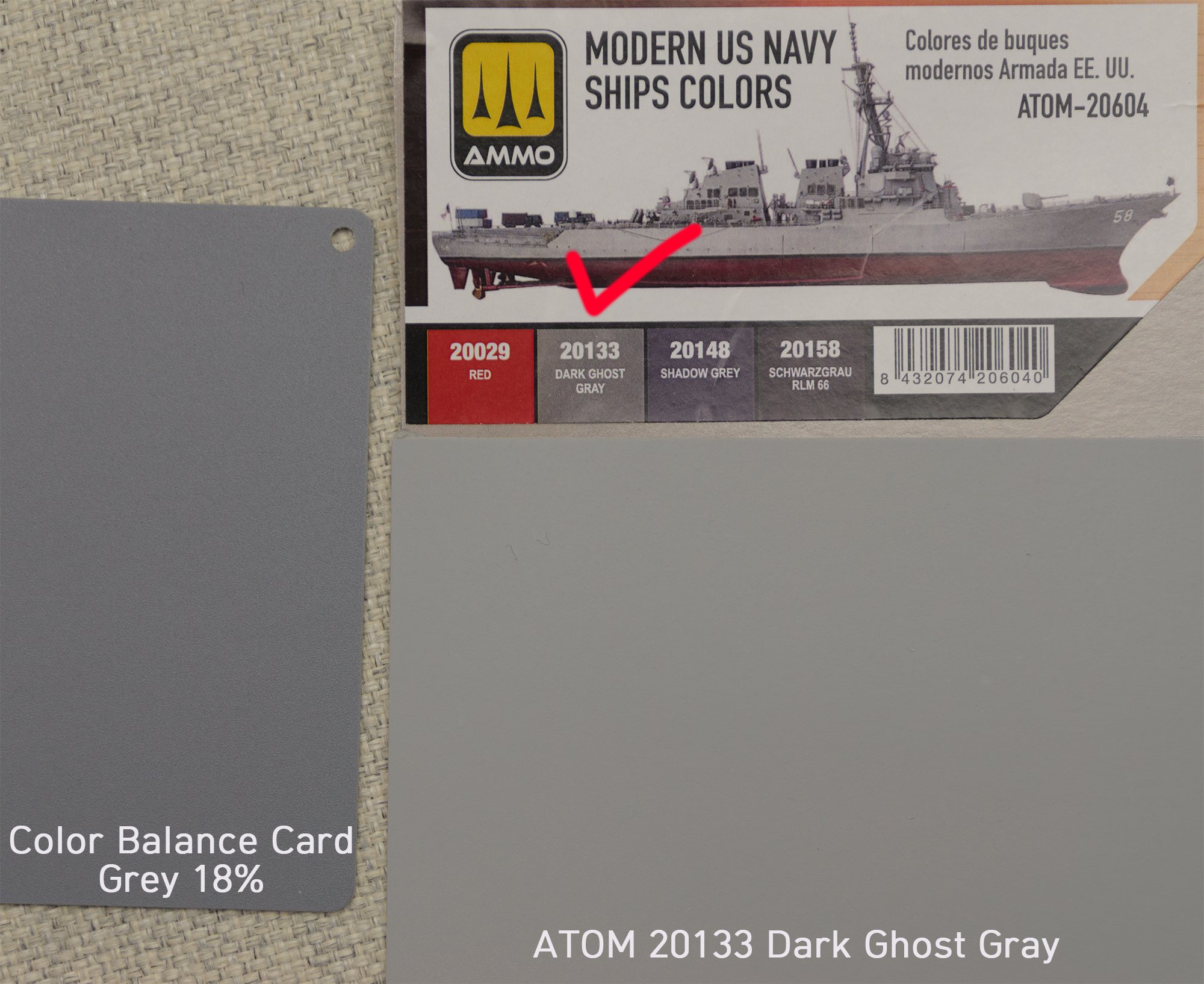
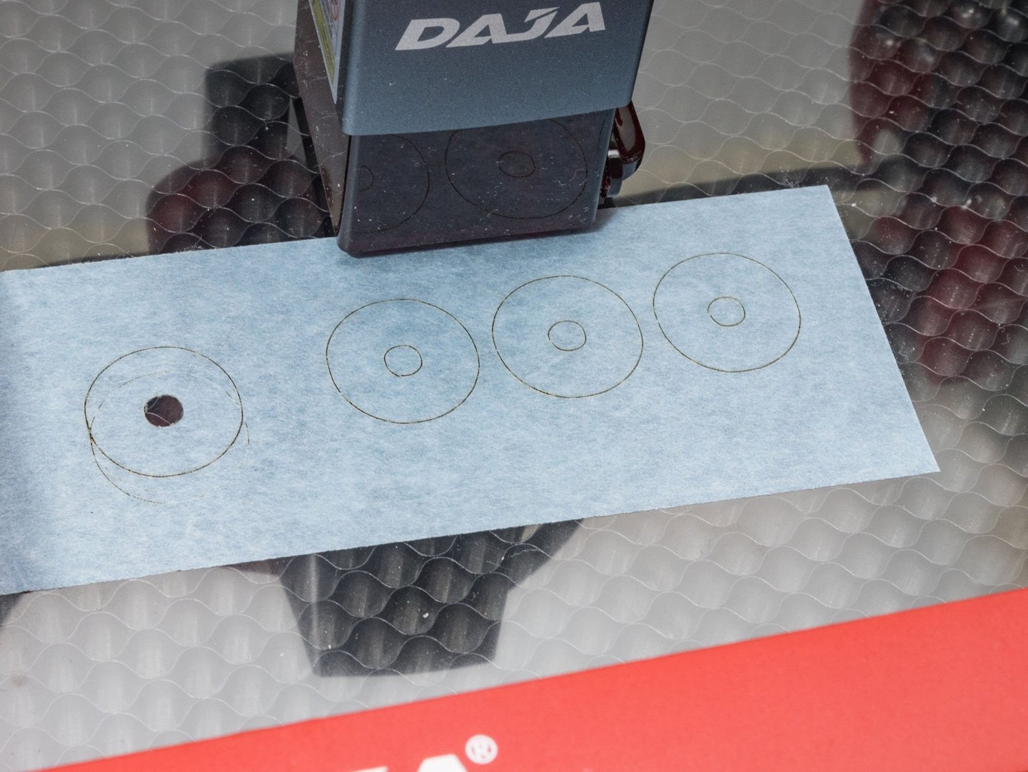
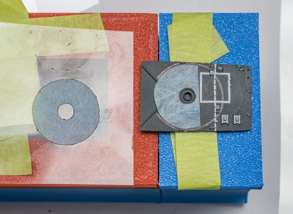
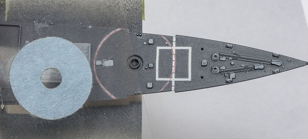
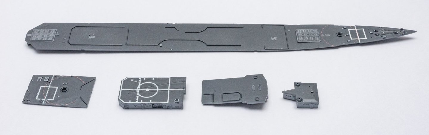
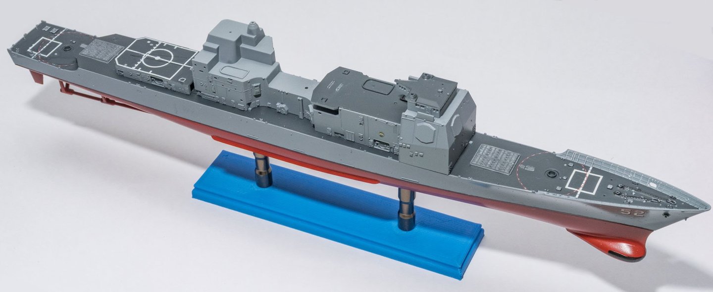
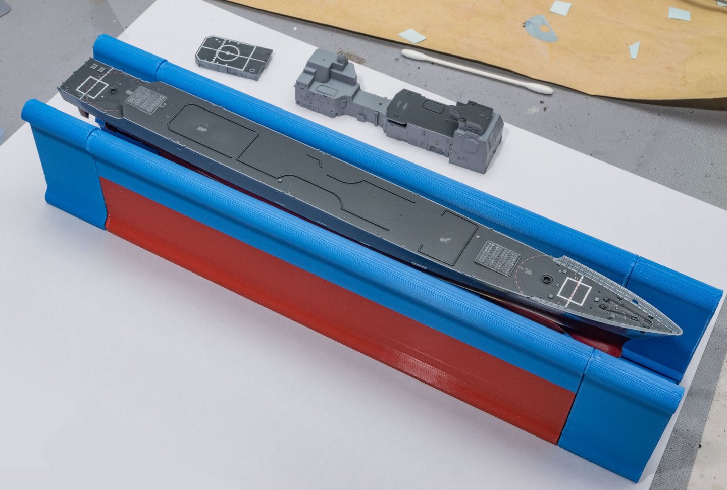
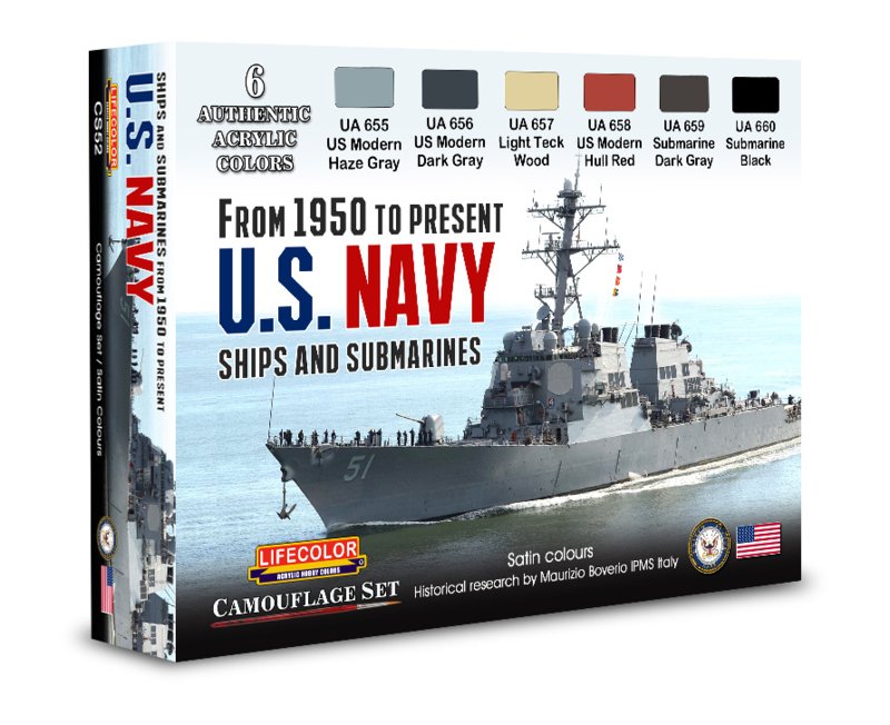
 The next project is 1/700 Ticonderoga class cruiser USS Bunker Hill CG-52 1991 Gulf-war version from Flyhawk. Before I started the modern US Navy ship kit, I inspected a new acrylic paint set. AMMO ATOM is a brand-new 2024 water-based acrylic paint to compete with stronger environmental regulations. It appears to be the most recent and advanced high-quality paint set. However, the color selection of the ship color set is not suitable for ship models. (From 1950 to present US NAVY ships and submarines, Lifecolor CS-52) This is the closest color set to Snyder and shorts' paint chips I've ever seen. In this project, I used Lifecolor UA-655 and UA-656 colors. This kit has several tricky waterslide decals. I used a laser cutter to cut half-inch sized circles. Not bad... The burned edge of masking tape was very rough. Should I use my Silhouette CNC paper cutter? Deck and decals are done. Temporary assembly. I also made a custom handling grip. I can't build any Flyhawk kits without the handling grip.😎

- 9 replies
-
- 7
-
-
- Bunker Hill
- Flyhawk
- (and 2 more)
-
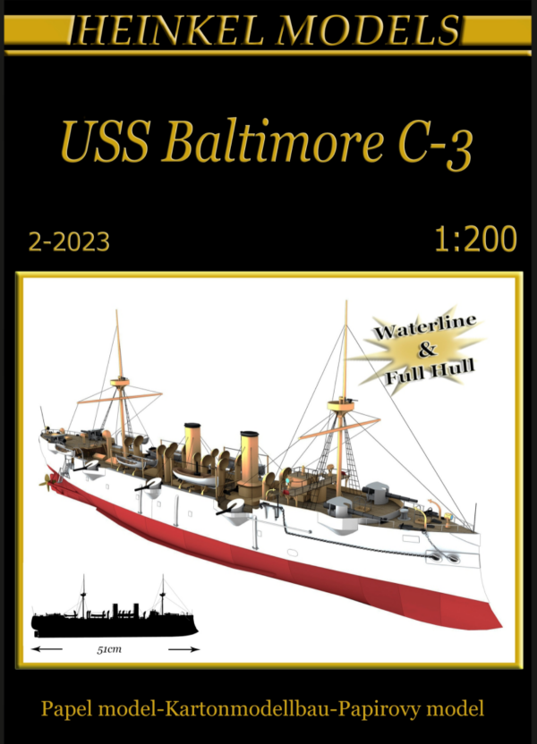
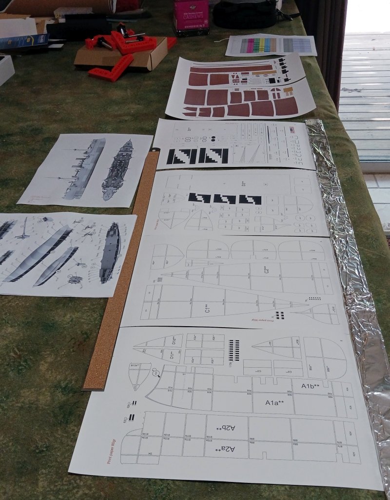
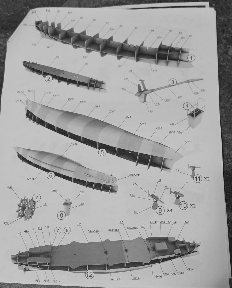
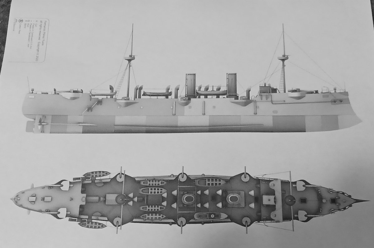
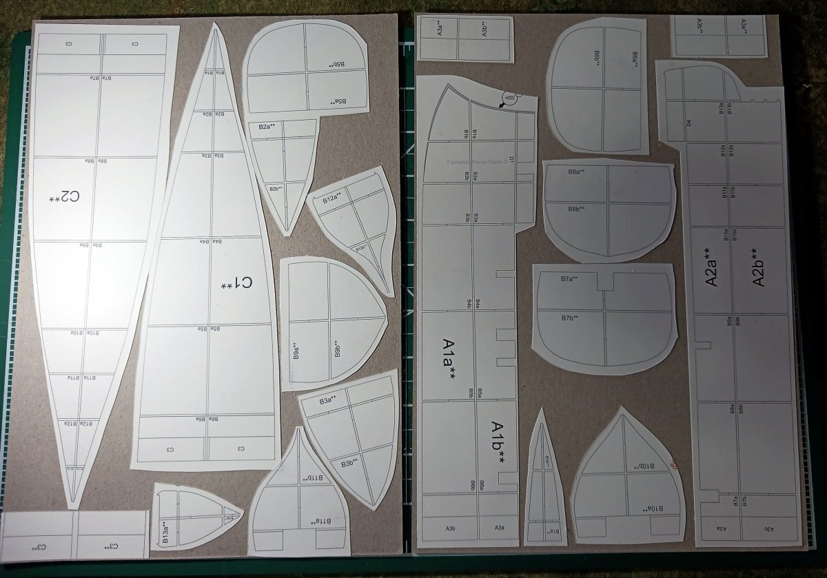
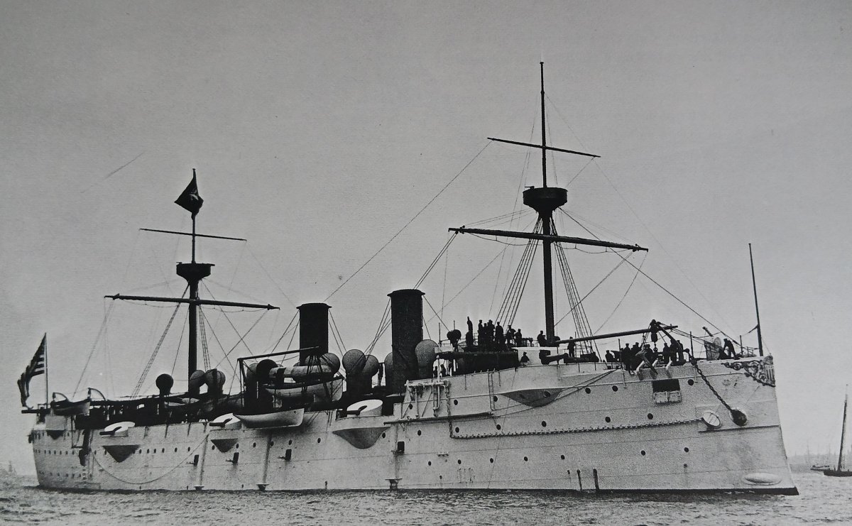
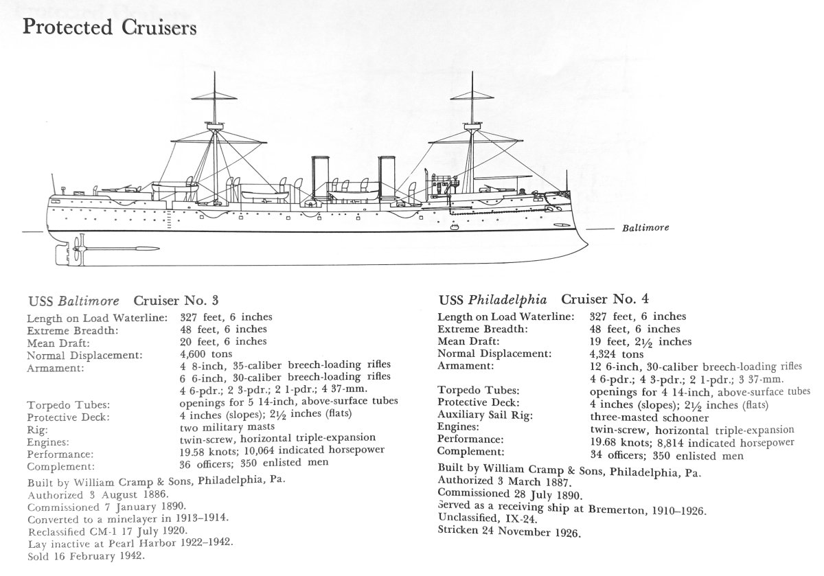
 Here we go again... One of the great benefits of card models is that, in their un-built state, they can literally occupy zero space. Nada. No storage concerns, whatsoever. Perhaps the wise builder invests a little storage space in getting professionally printed kits with all the bells and whistles, laser cut formers, etc. I've never been accused of wisdom. There's a model designer whose work I have frequently admired. Company name of Heinkel. I believe the designer is Fernando Perez Yuste. He's designed a lot of American Civil War ships and has expanded into the pre-Dreadnought era. When I saw the USS Baltimore show up on Wargame Vault I decided to splurge and add it to my virtual stash. (I say splurge but let's face it, card modelers seldom really spurge--Shipyard models excepted. The Baltimore cost me $15.25US. And I had credit on WV so in reality it cost me nought.) A couple of weeks later WAK published the Baltimore for a princely sum of $12.82US and they can provide laser cut parts and gun barrels, etc for additional funds. (Oh my, just noticed WAK's on-line shop is closed due to the floods in Europe. Here's hoping for a quick return to normal life for everyone!) So a little about the USS Baltimore. The US Navy was caught in the financial doldrums for twenty years after the Civil War. In the 1880s and 1890s the Navy reinvented itself by designing, purchasing and building new, high-tech steel hulled ships. The Baltimore was one of the first generation of new armored cruisers of the new navy. Built to a British design, she was launched in 1890. The following pictures are from John D. Alden's "American Steel Navy": I won't detail the history of the ship here. She's pretty well documented on Wikipedia and there are many photos at Navsource.org. But, like the more famous Spanish American ship USS Oregon, the Baltimore fought in the Spanish-American War, served as a mine layer in WWI and was present (though as a hulk) at Pearl Harbor in WWII. A last poignant picture from Navsource.org, 1944, just before being scrapped: The Model This is my first Heinkel model. There is a bare minimum of written directions but the pictorial instructions should be enough. It's also the first test of my laser printer. I will state, however, the design is for A4 paper. North American builders should be aware that if you print at 100% on letter size paper you will most likely lose the top and bottom edges of the model parts sheets. You can print on legal size paper without issues. Also be aware that the finished model is a full 51cm long (20+ inches). So not really a small model. Now, I've been planning on this build for a while. Consequently, I've been stocking up on that cool European 1mm card supplied by Seahorse as I've worked my through the Revenue Cutter. I've printed out most of the interior parts and used a glued stick to laminate most of them to card. Cutting will probably begin tomorrow.
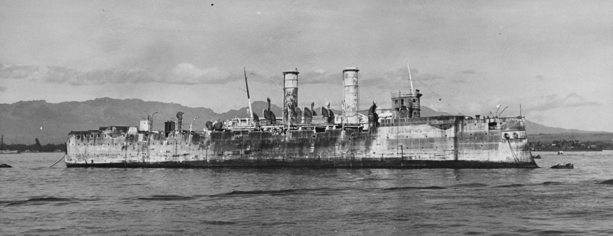
- 36 replies
-
- 6
-
-
- Baltimore
- heinkel models
- (and 2 more)
-
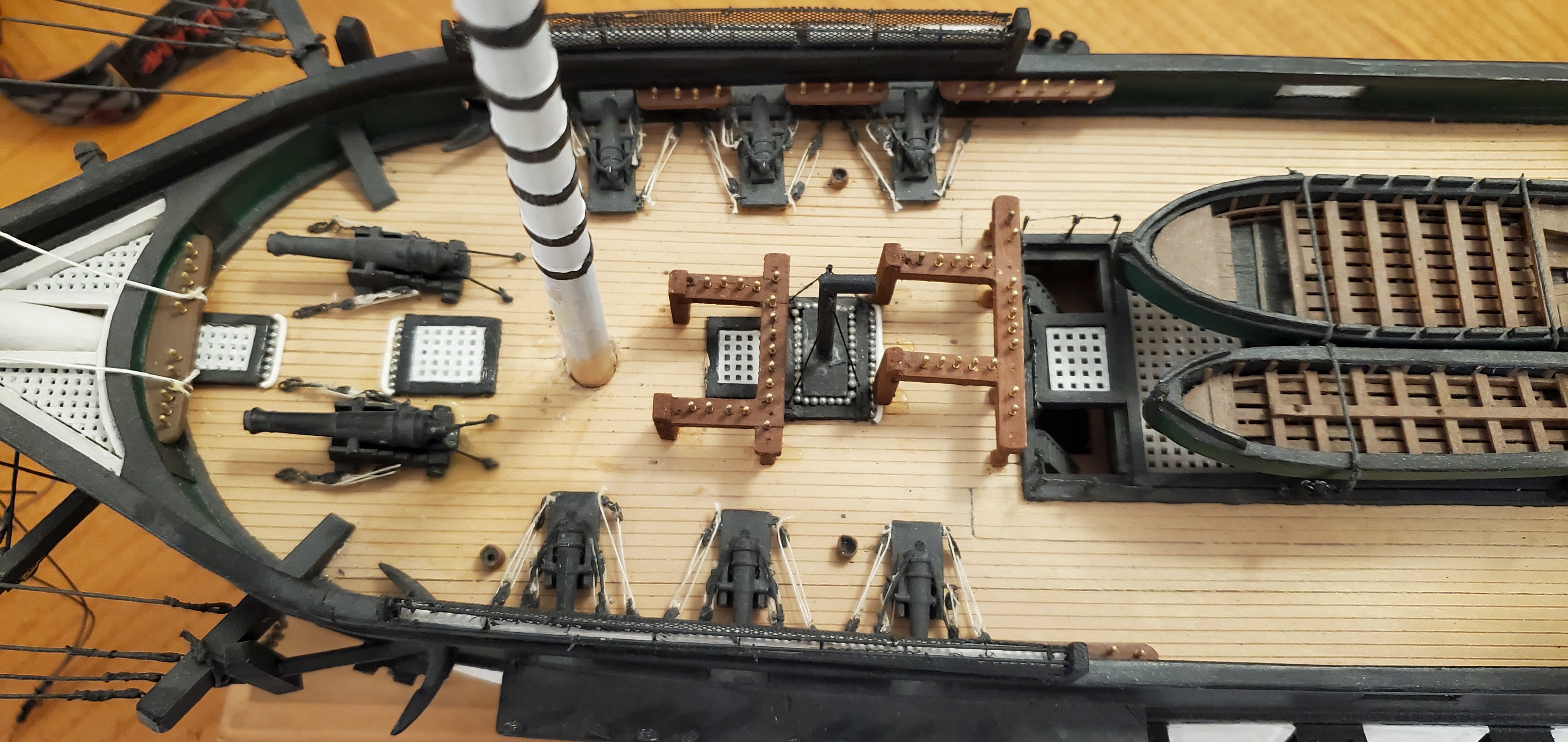
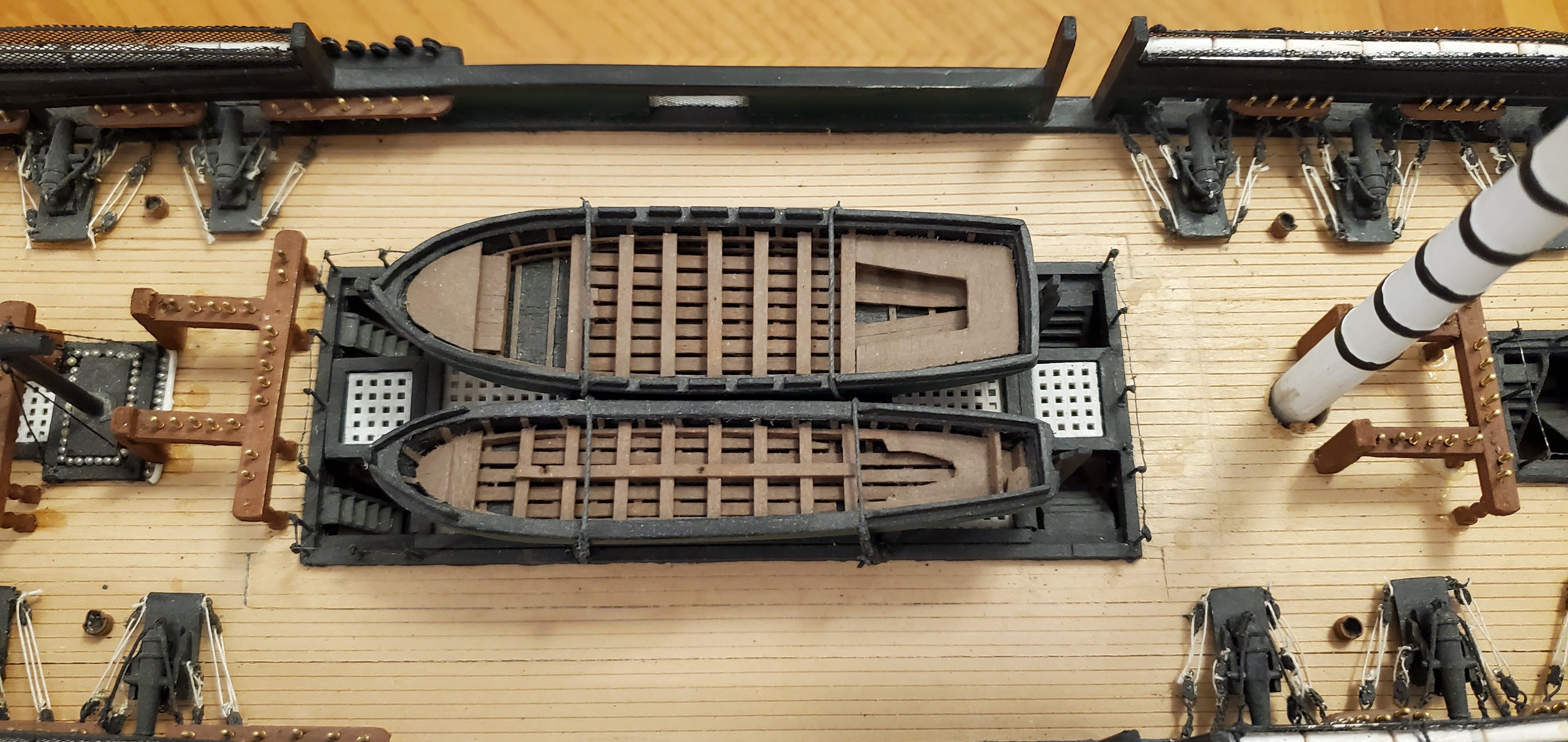
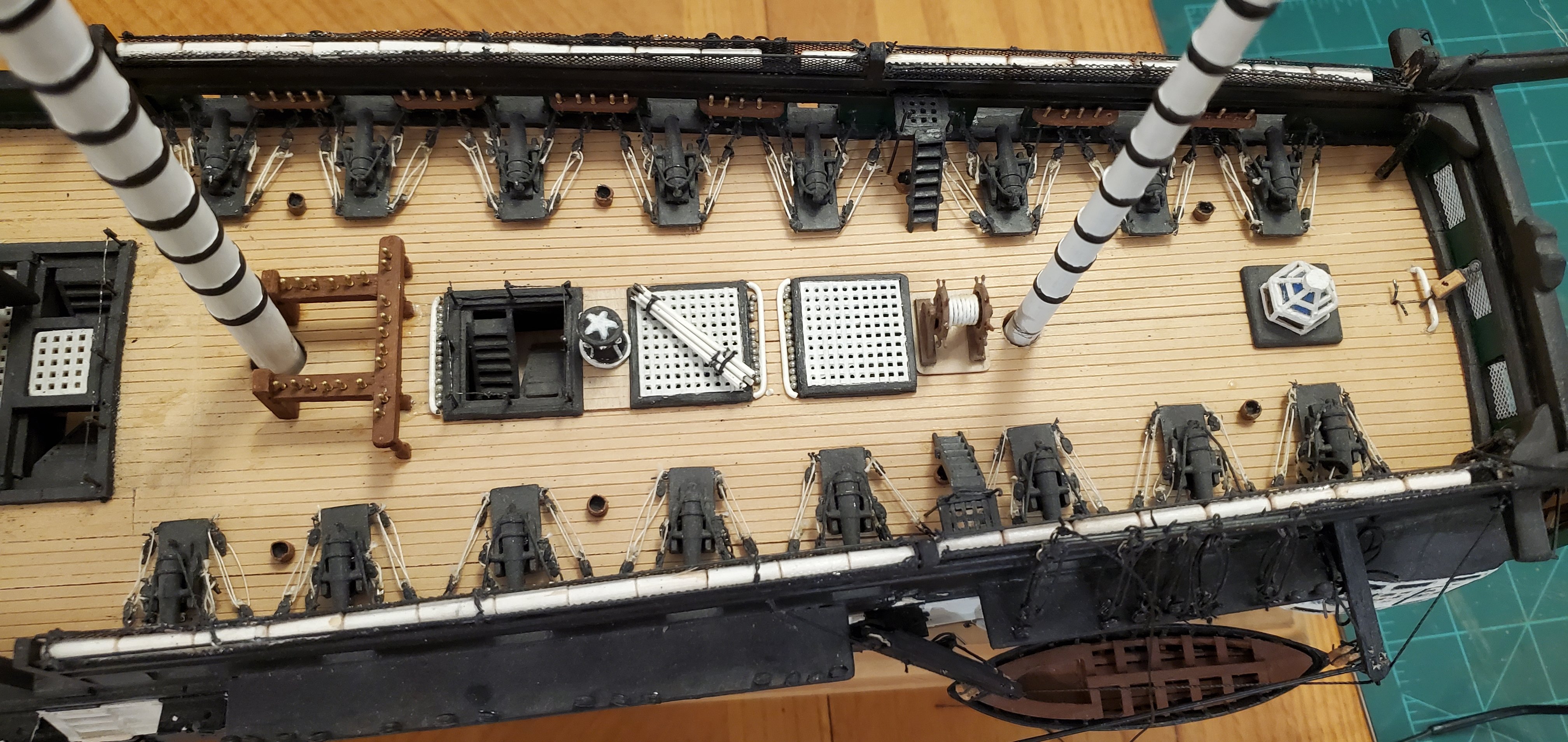
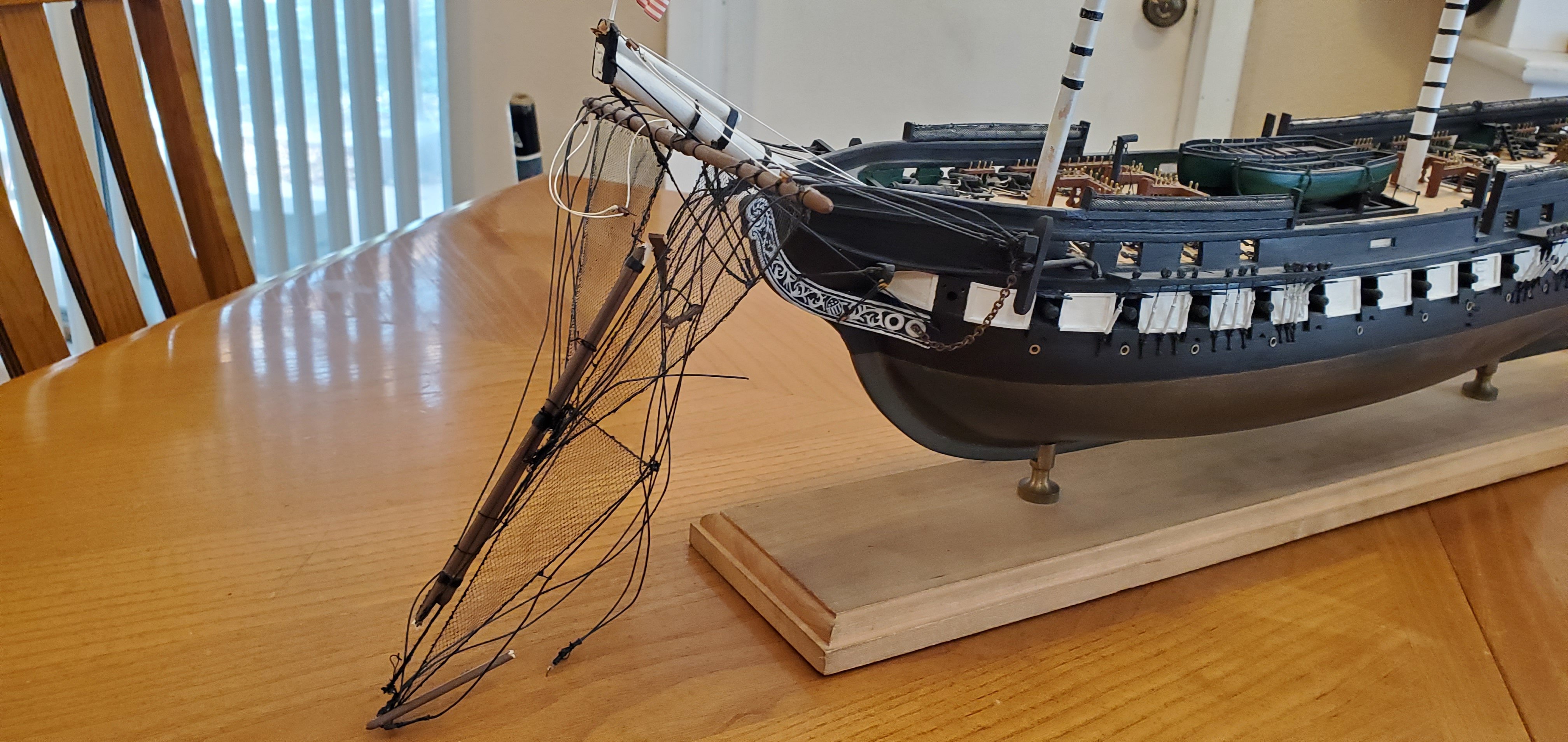
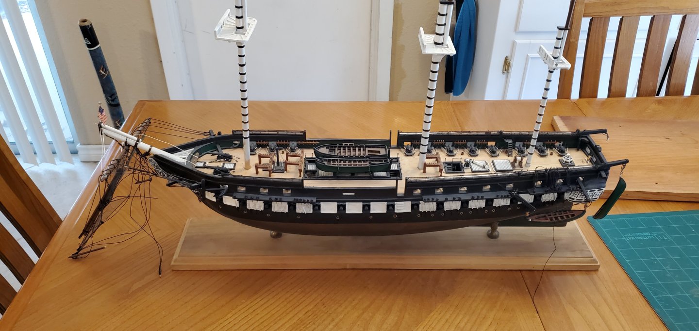
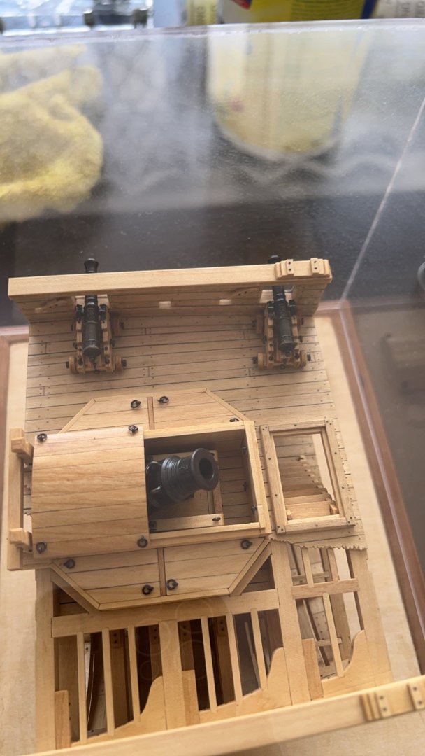
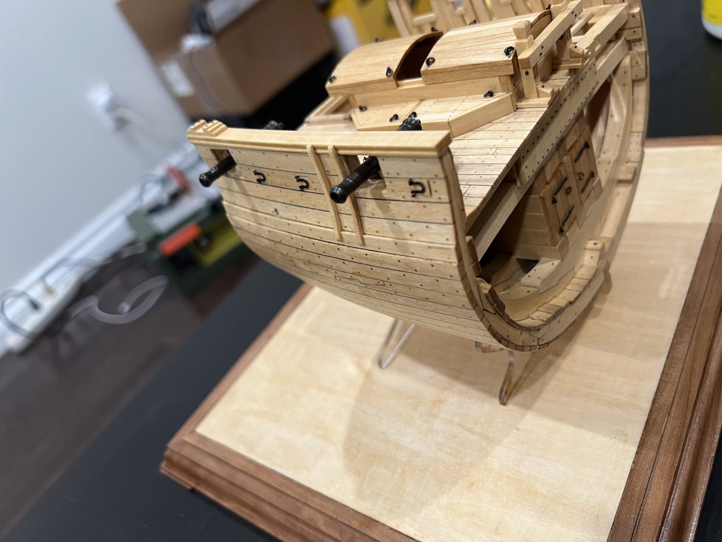
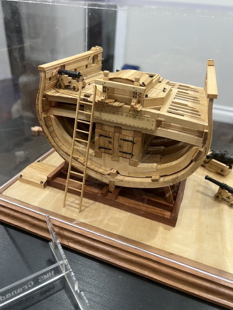
 A couple of months ago, @Keith Black sent me this MSW post from a gentleman in Austin, Texas who was looking for help completing a model. https://modelshipworld.com/topic/36787-looking-for-assistance-completing-model/ Since I also live in Austin, Keith thought this might be of some interest to me. He was right. The gentleman, Carson, was looking for someone to complete a model his father had been working on before unexpectedly passing away late last year. He and his family were hoping to have the model completed as a way to honor and remember their father. I contacted Carson, found out more about the model, and agreed to finish it up for them. I picked up the model earlier this week and have just started to examine it and the kit's documentation. I will also be studying some of the Constitution build logs out here on MSW. Once I get my arms around the whole thing, I’ll put together a plan for how to attack this project. The model is the Blue Jacket Bicentennial Edition of the U.S.S. Constitution. Carson’s father had done a significant amount of very nice work on the model - completing the hull, outfitting both the gun and spar decks, stepping the masts, and completing the complex bowsprit rigging. It appears he was on the verge of diving into the real fun that goes with all the standing and running rigging. Somewhere along the way, the model took some hits and suffered a bit of damage. But just like the real Old Ironsides, the model survived with the hull intact and just a few repairs needed. So this project will be a repair job at first followed by completion of the construction. For repairs, here’s what I’m seeing on initial review: 1. The most significant damage is to the bowsprit which is broken in a couple of places. 2. The sky sail pole on the main mast was broken at some point but has been repaired to a degree. 3. The davits for ship’s boats on both sides are broken off. 4. The masts have been stepped, but the glue bond on the fore and main has come undone, so they will need to be re-stepped at the proper rake. 5. The netting for the hammock storage has some minor dings. Other than that, I believe, the model is in good shape and I hope to complete the model in a way that properly honors Carson's father. I know there are many folks here on MSW that have extensive experience with the Constitution and perhaps the Blue Jacket kit itself. So please do not hesitate to offer comments, critiques, and suggestions. I welcome it all. Following are pictures that show the current state of the model. I’ll start with my favorite which shows all the damage to the bowsprit assembly. Yet Old Glory survives and still waves proudly above it all!
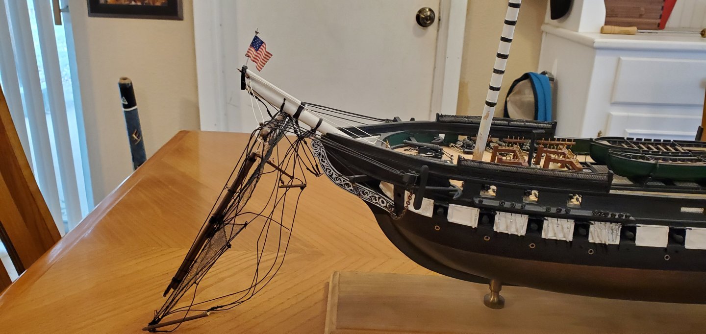


- 301 replies
-
- 14
-
-
- Constitution
- Bluejacket Shipcrafters
- (and 1 more)
-
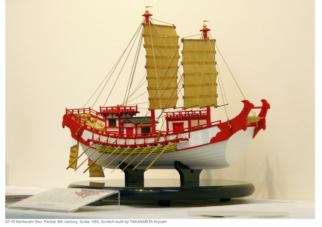
Time for a new SIB project. And this one has a deadline. But I’ve got plenty of time since I just have to finish it before July. About a year and a half ago, I reconnected with an old college friend and roommate that I had not seen since the late 80s. He found out about my SIB work and asked me if I would make one that he could give to his wife for her birthday in July (hence the deadline). We got to talking about what the subject of the project should be and he asked if I could do one with a Japanese theme. He and his family lived in Japan for several years and loved the artwork and culture. So he thought his wife would like something reminding her of their time in Japan. I began digging around for historical Japanese ships that looked interesting or had a compelling story. Surprisingly, I didn’t find a whole lot to choose from. I’m fond of warships, but I thought one of those might not be the best thing for his wife’s birthday present. I finally came across a ship that caught my eye. It did not have the most compelling story behind it, but it had some really cool features and was very representative of Japan’s non-military nautical history. The picture labeled the ship “Kentoshi-Sen”. With further reading, I learned that Kentoshi is not the name of a particular ship. It translates roughly to “ambassadors dispatched to Tang”. So it’s actually the name of the nautical expeditions carried out by Japan in the 7th century and the picture is representative of the types of ships used in the expeditions. The purpose of the expeditions was cultural exchange with neighboring China. During the Japanese Nara period and the Chinese Tang Dynasty of the 7th century, Kentoshi-sen ships ferried Imperial Japanese Envoys to China. The Japanese envoys included scholars, engineers, diplomats, monks, court officials and merchants. They would return from China with new ideas surrounding engineering, architecture, and vocabulary which had a significant influence on Japanese culture. They also brought back items such as glass, musical instruments, textiles, scroll writings, and many other exotic curiosities. The cross-cultural exchanges began with 5 missions between 600 and 614 followed by 18 or 19 missions from 630 to 894. The last mission was in 838, thus ending the period of active diplomatic relations between Japan and China until the 15th century. Current pictures of Kentoshi-sen ships (as well as a full replica built in 2010) are based on drawings from the Toseiden emaki scrolls dating back to the 7th century. There’s also a Lego version of the Kentoshi-sen available, so the subject is not as obscure as one might think! My goal for the project is to make the subject, bottle, and presentation authentic Japanese. So for the bottle, I wanted some type of Japanese adult beverage bottle. I searched all the stores around Austin but could not find anything suitable in my price range. The cheap stuff all had frosted or opaque glass and the clear bottles were way too expensive. Then I had an epiphany – eBay! I did a search for empty Japanese liquor bottles on eBay and found one I liked for $20. It was an empty bottle of Kujira RyuKyu Whiskey, single grain aged 20 years. Out of curiosity, I did a quick search to see what a new (full) bottle would cost. An eye-popping $400 - $700 depending on the store! So an empty bottle from eBay it is!! I was telling my son about the bottle and I mentioned that it had a cool picture of a blue whale on the label as well as the box the bottle came in. He said, “Duh Dad. Kujira is the Japanese word for whale.” Oh.

- 106 replies
-
- 12
-
-
- Kentoshi-Sen
- bottle
- (and 1 more)
-
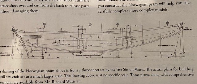
 This is kind of my second build, I finished the ‘Lowell Grand Banks Dory’ and got about half way through the ‘18th Century Long Boat’ both by Shipways when I decided to shift to this boat the ‘Norwegian Sailing Pram’. This is the second in a beginner series of “progressive model tutorials” designed by David Antscherl. I did learn a lot about wooden ships and how to build wooden models from the Dory. I decided to shift sails when I noticed that the Pram was finally for sale by Model Shipways and I thought I could use the additional learning experience especially rigging. The Long Boat rigging is supposed to be fairly simple but the Pram rigging looked even simpler. One thing I’ve noticed is that the instructions for these ‘beginner’ models seem to assume the builder knows a fair amount of how to build a model boat. In my years I’ve built many plastic models but not wood models and I’m really a novice. So, I’m keeping track of recommendations to improve the instructions as I progress through this build. First, I’ve notice that the Pram instructions are missing a lot of instruction points that could easily be corrected with a few annotated pictures and plans. I strongly recommend that a set of scaled plans be included in the kit. The only plan is the one below that is from a real pram design. Even though the Dory was a simple boat to build, I used the plans constantly to figure out things that were not written in the instructions.
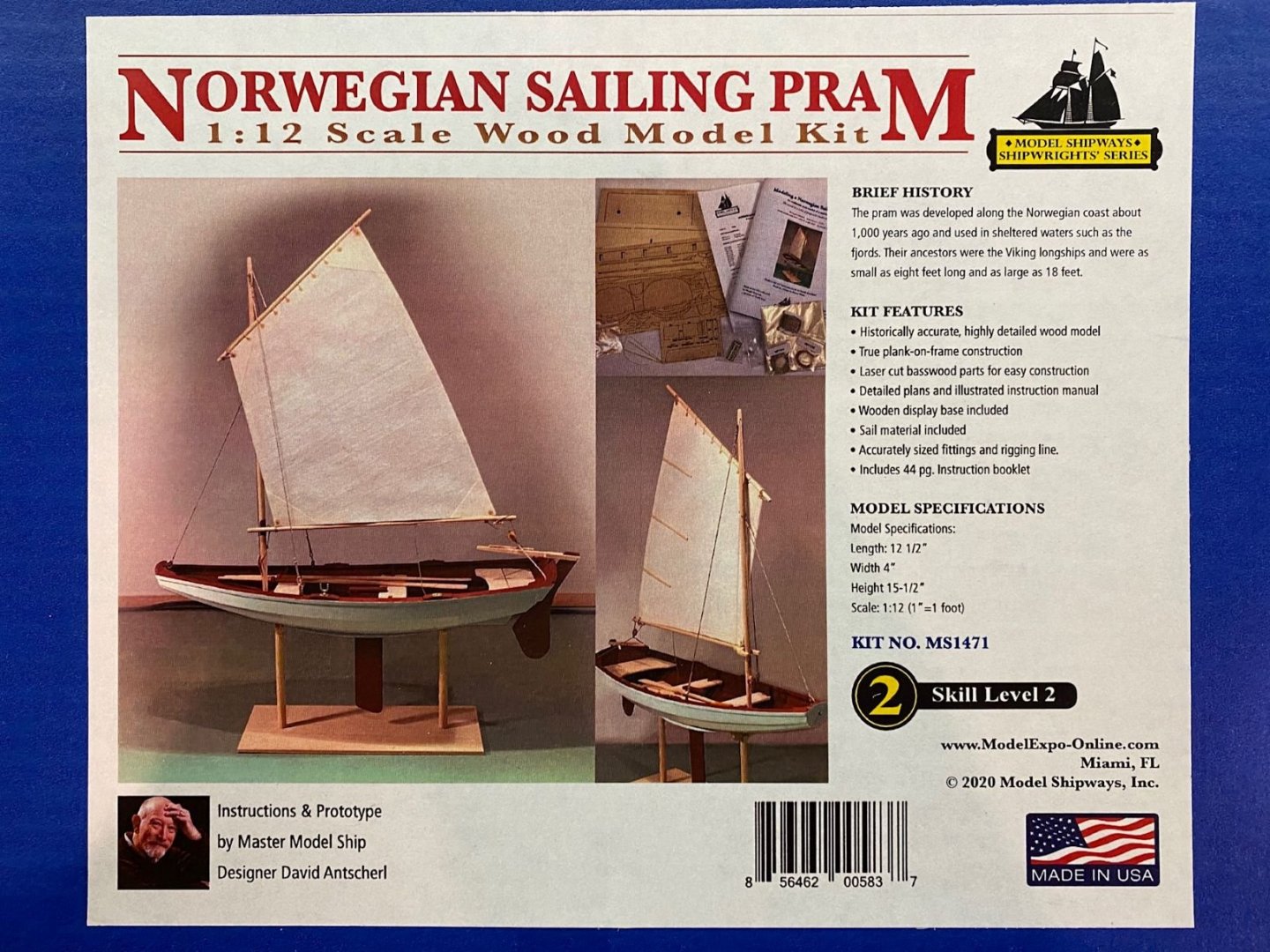
- 53 replies
-
- 5
-
-
- norwegian sailing pram
- model shipways
- (and 1 more)
-
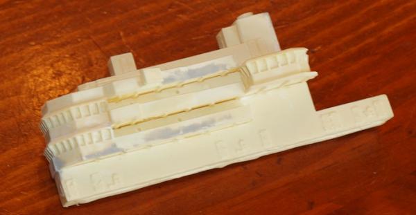
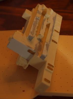
 I looked for a long time to try to find a 1/350 scale model of my Dad's carrier, the New Orleans. The only kit in this scale, or really any scale, of the LPH-type carriers, was this one by Iron Shipwright's. As much as I hate working with resin, this was the only game in town. The original kit was made as LPH-9, the U.S.S. Guam and made as it was retrofitted to the 1985 time frame. Dad served on the New Orleans during 1969 - 1970, so a good bit of backdating is in order. I apologize to those who I told I was going to start a build log on this, but with two young kids my modeling time is sorely limited. After moving at the pace of a directionally challenged snail, the island is starting to come along fairly nicely. Please excuse the fact that I don't have any pictures of the parts before starting, but I was a little absent-minded! So anyway, here goes! The kit, in some areas, is very well detailed - but in others, it really needs some work. Starting with the island, I purchased a set of PE doors from White Ensign (who happens to make excellent PE items). The molded resin doors are some of the things that need re-working. Although some may say otherwise, my AMS (advanced modeler syndrome, or to put it in terms - having to update everything to make it as accurate as possible) just won't let me leave well enough alone. Going from pictures of the ship from the 1969 time frame, I am also reworking the island. It is difficult to see in the photos, the walks have been extended using white sheet styrene. I also had to replace the back wall of the island with styrene due to poor forming of the kit items. As you can see from the photos, some of the doors have been replaced and also all walks have been rebuilt. Also noticeable is the use of Mr. Surfacer (500) and Tamiya putty to help with corrections. Please excuse the quality of my pictures - I make no claim to be a photographer! Updates will be posted as soon as I can, which at my current pace... Thanks, Eric

- 176 replies
-
- 3
-
-
- new orleans
- iron shipwrights
- (and 2 more)
-
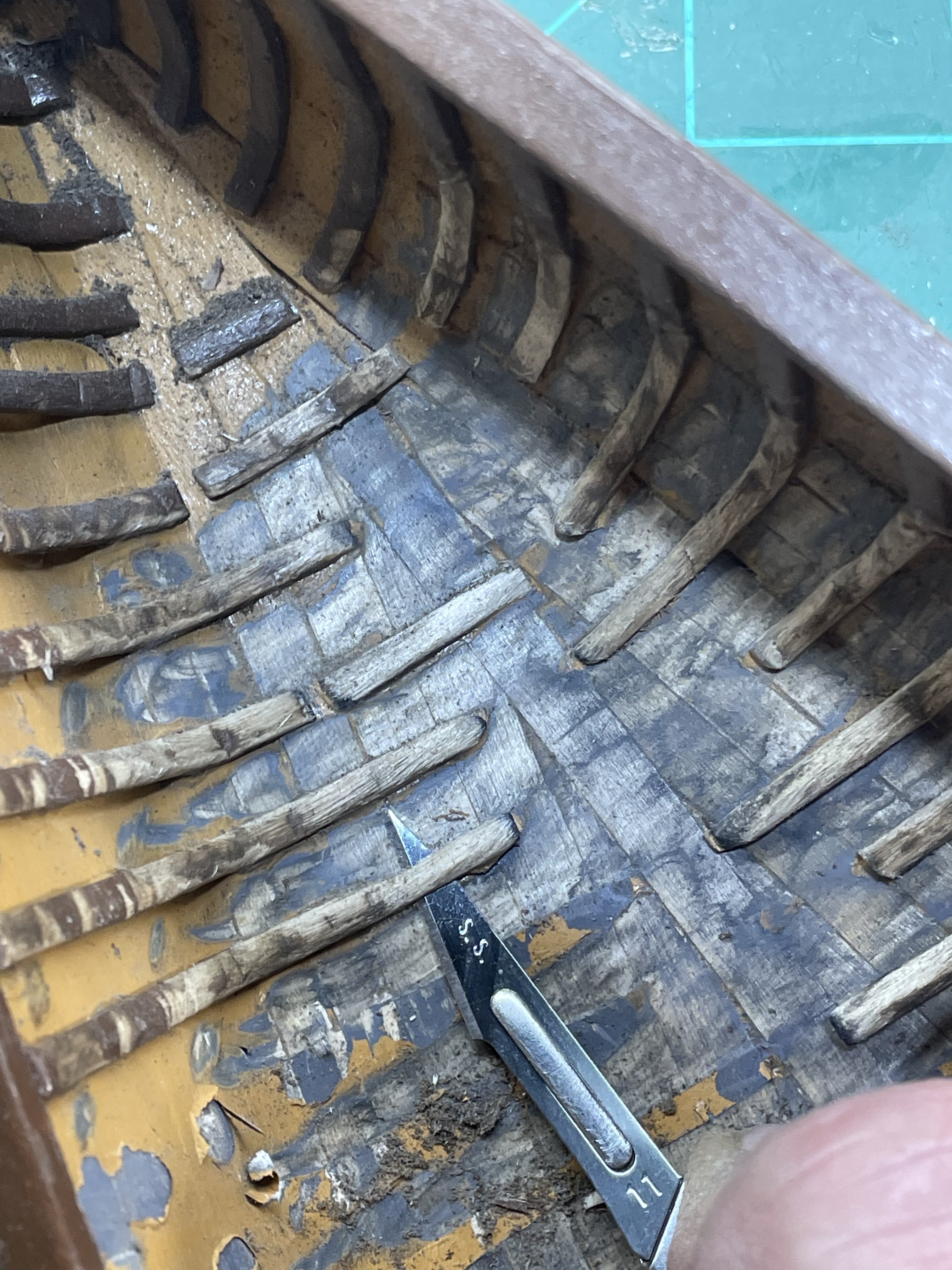
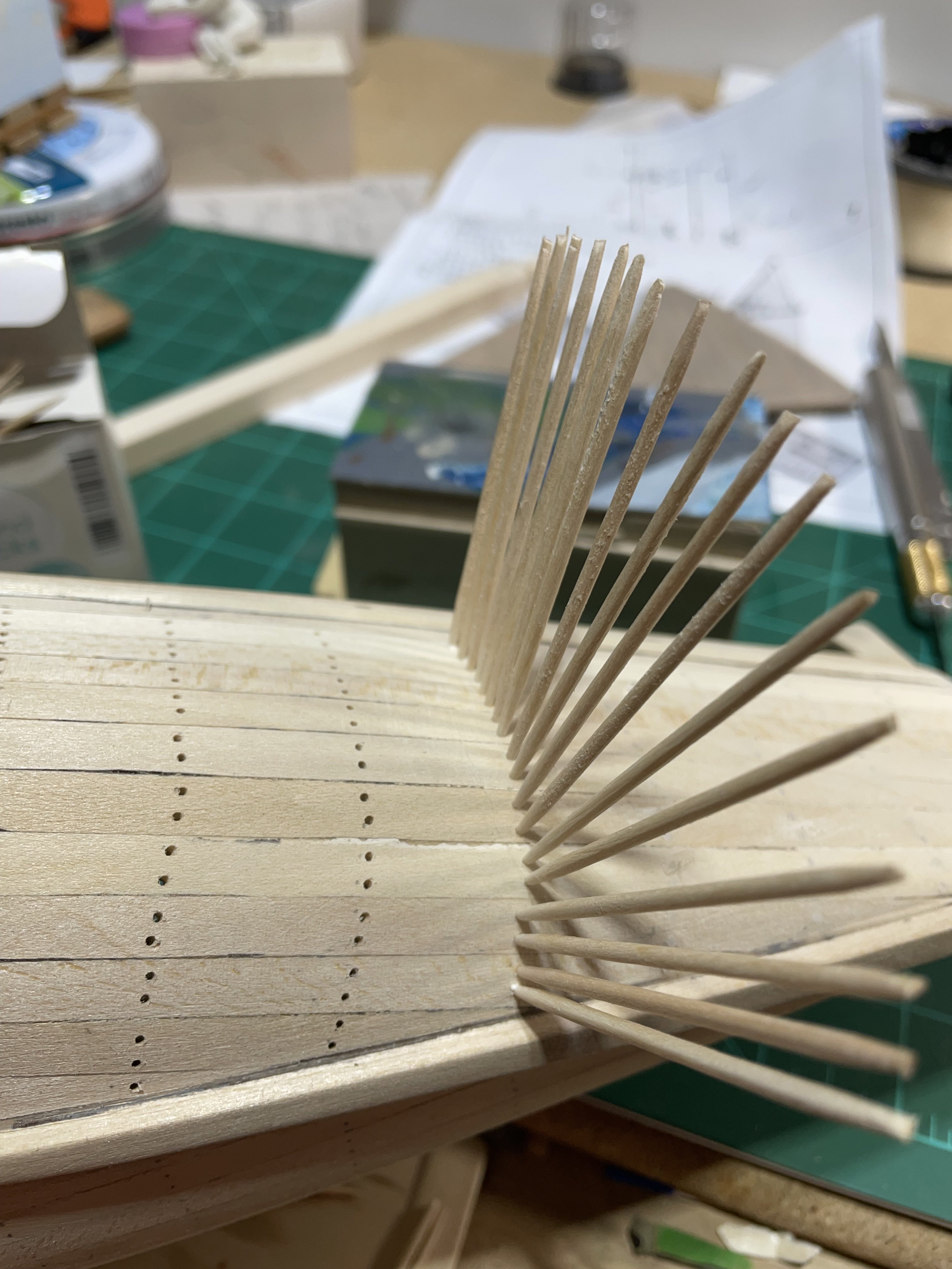
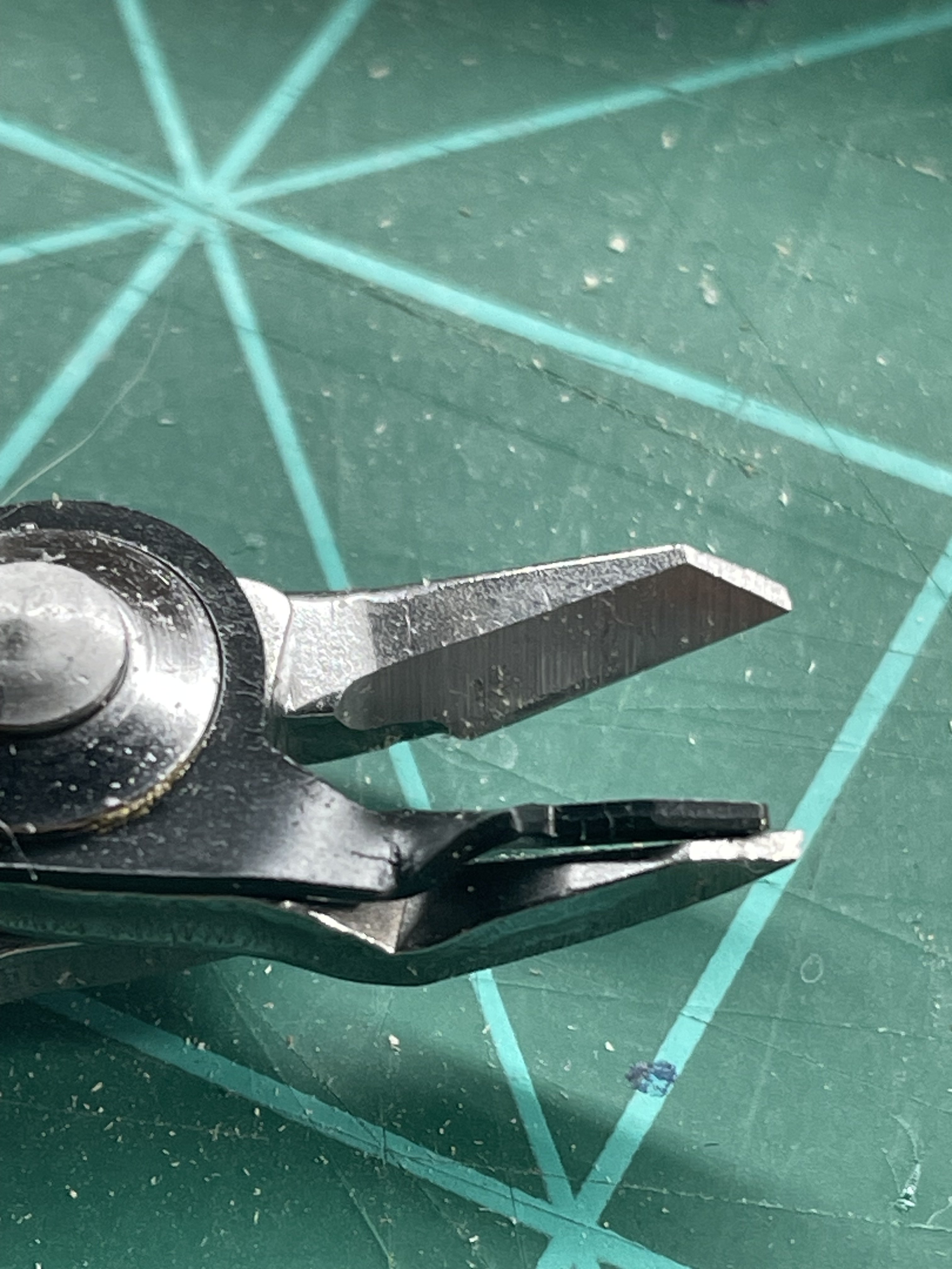
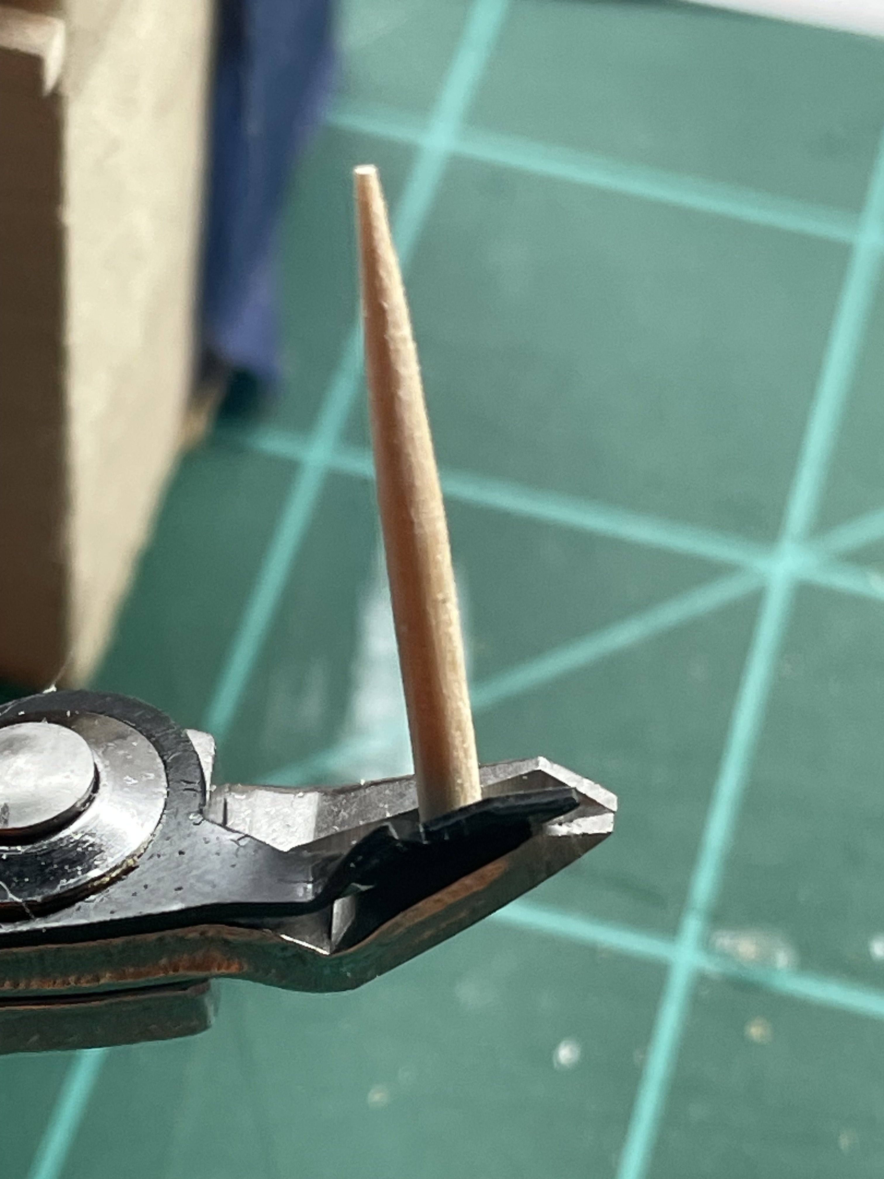
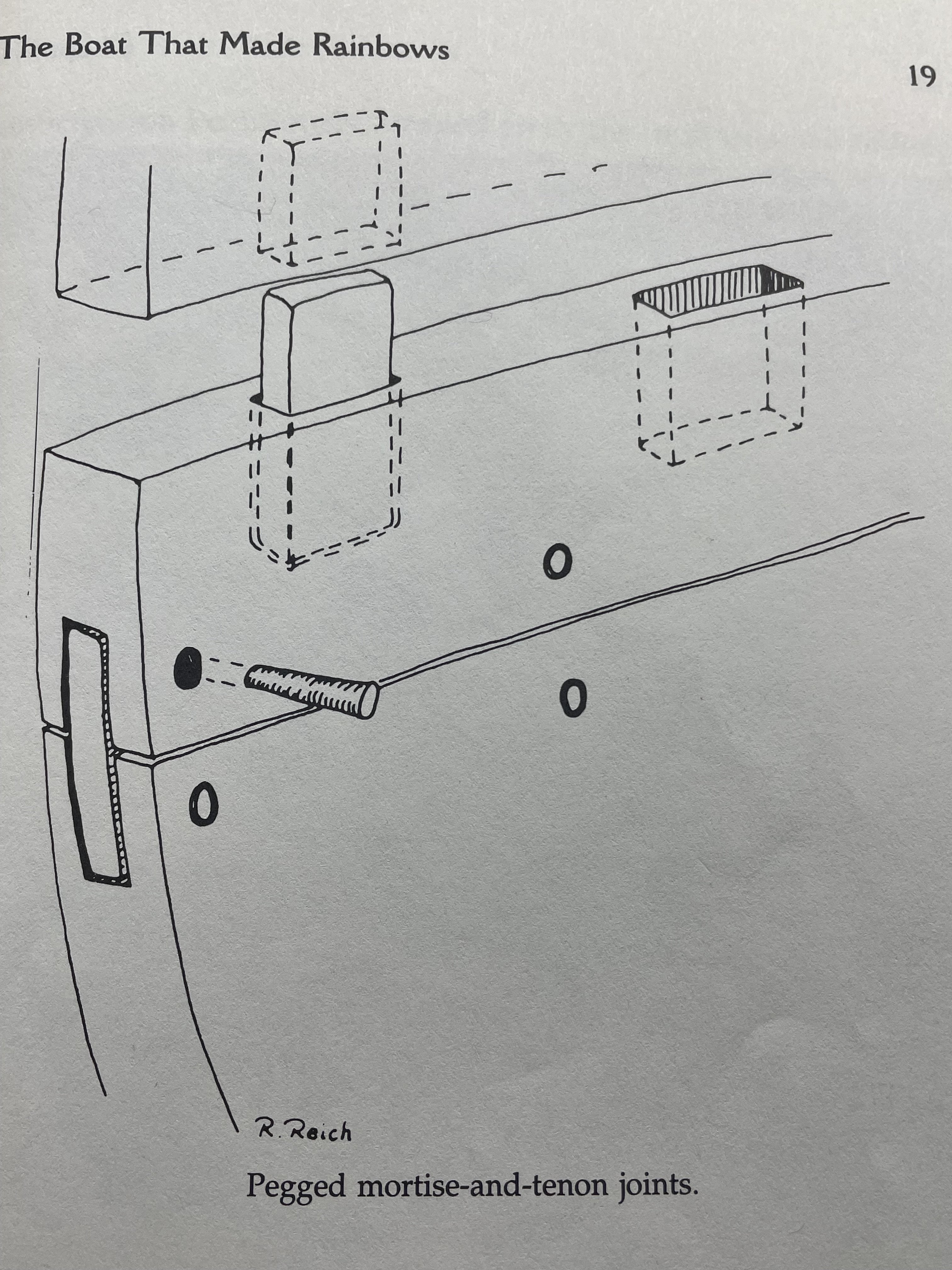
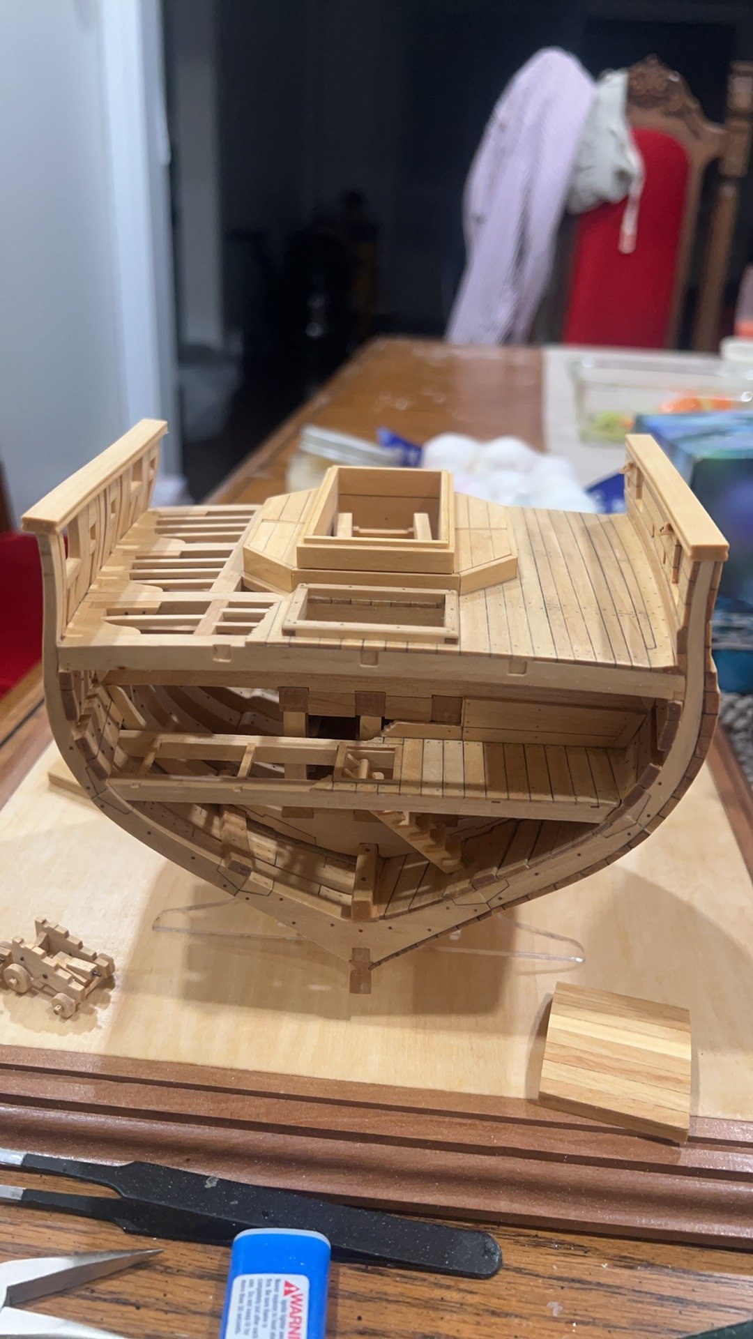
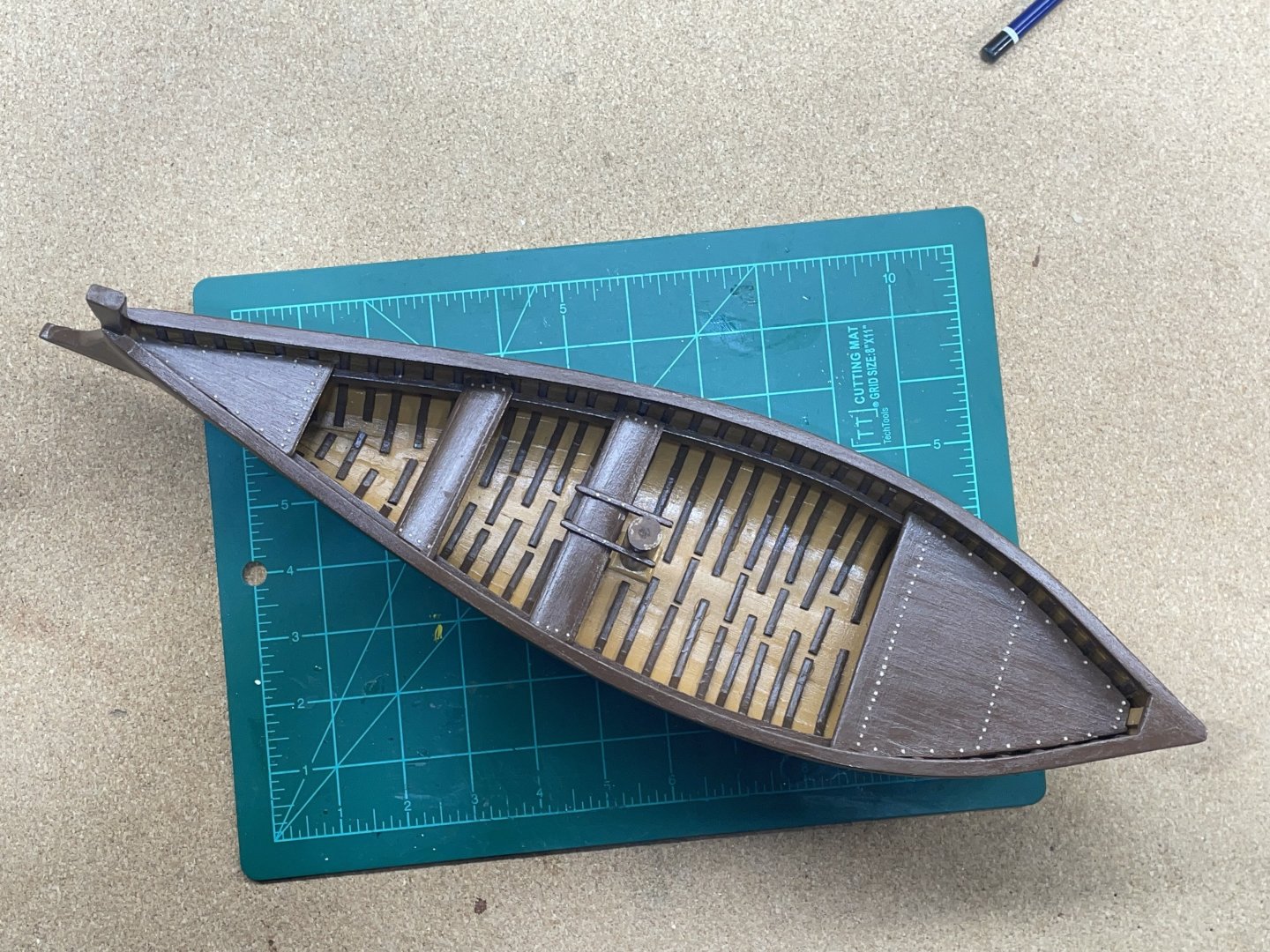
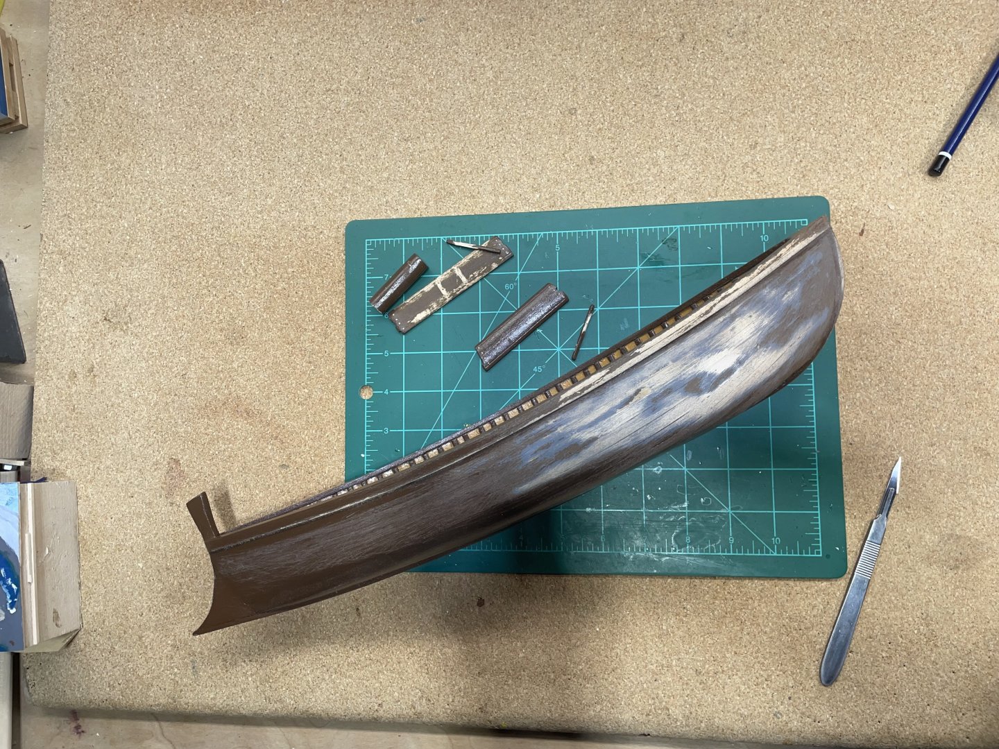
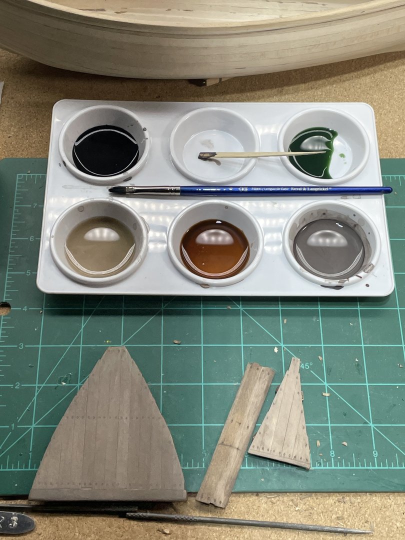
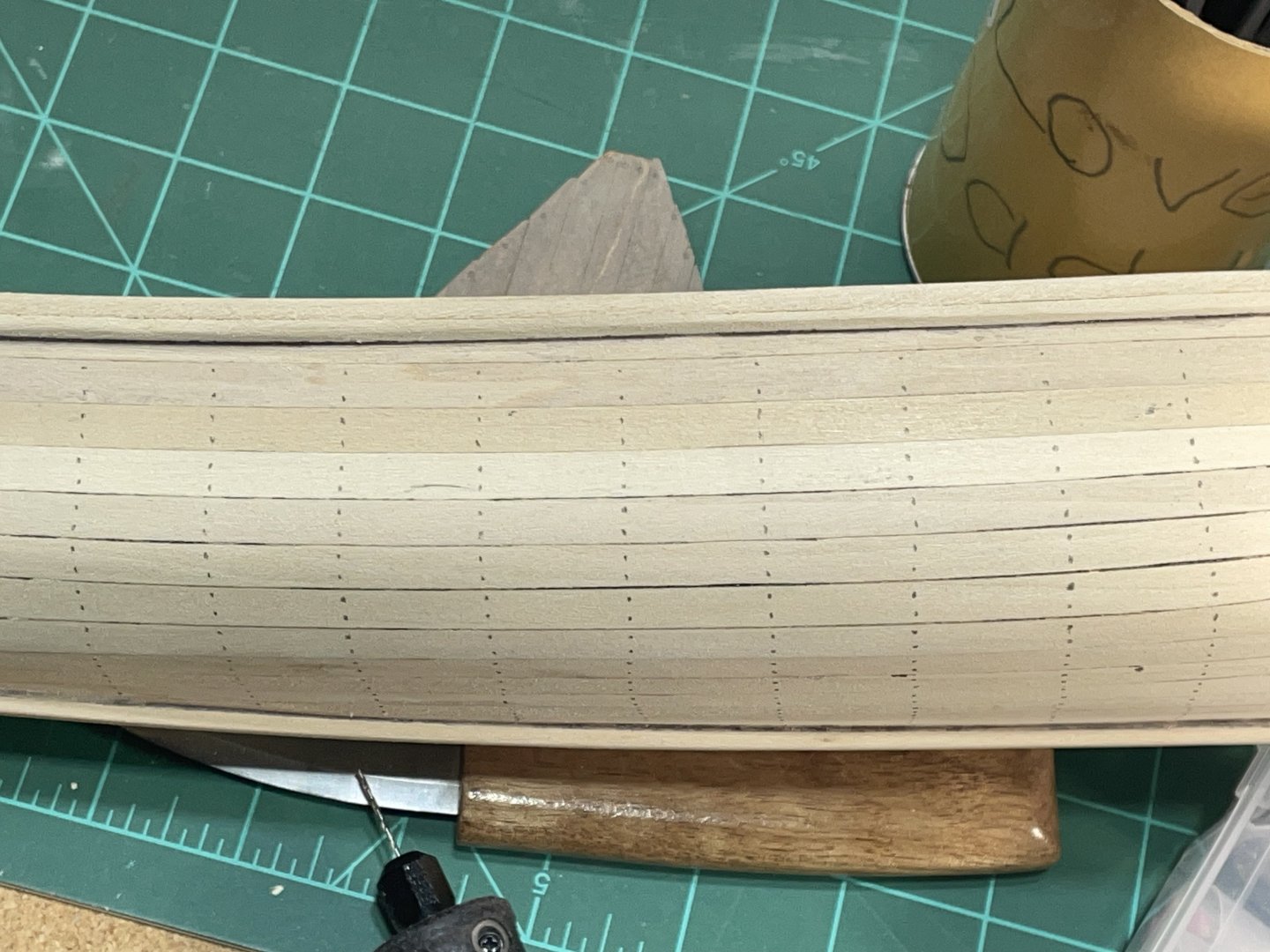
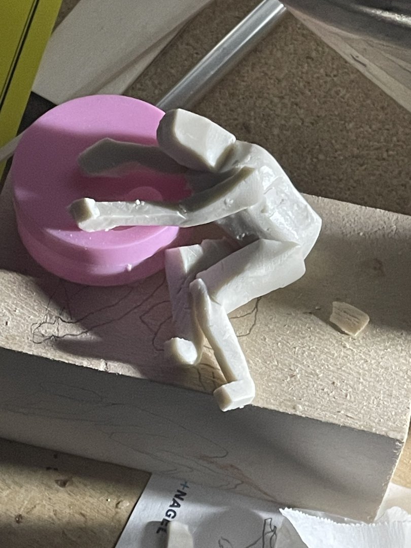
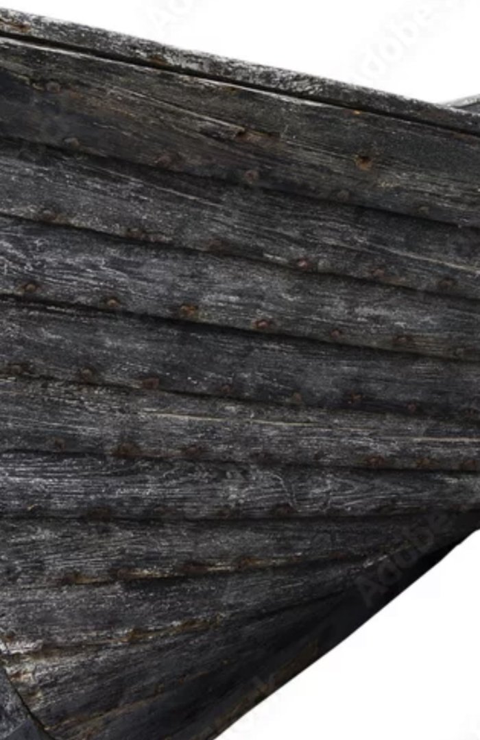
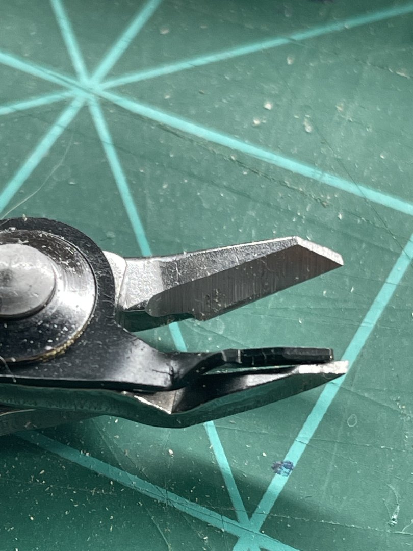
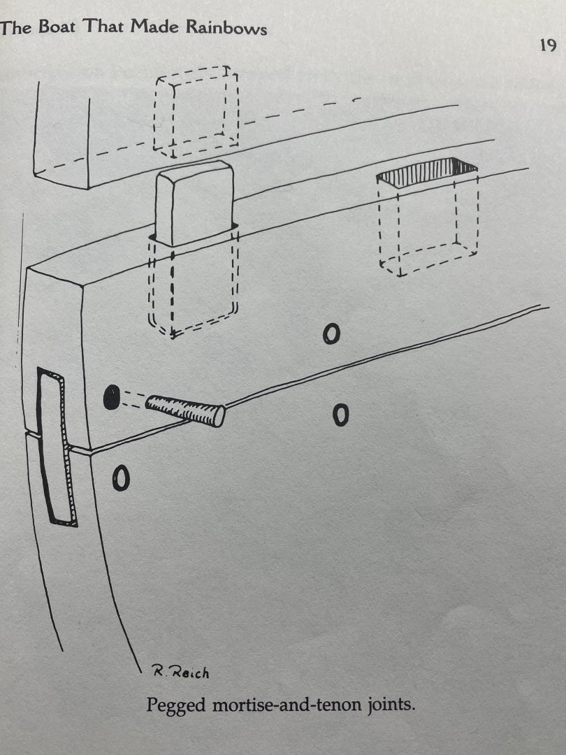
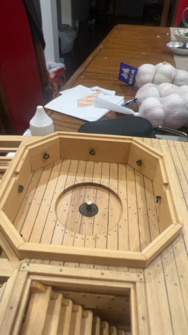
 After building the Scott Miller SoG kit. I reused the strongback and purchased basswood strips from hobby lobby, to build another hull. It was my intention to provide a boat the grandkids would like to play with. Well come to find out, a first century wooden boat can not compete with any toy of this day and age:-) My plan is to strip all the paint off, and put a weathered natural wood look to it. I’ll also scale the mast and completely rig it. It’s been setting around taking up space and I know someone that would like to have it if I can make it look like nice decor. Here’s where I started. I had primed it and put about 6 coats of paint on it. That took some time to get sanded off. And the inside of the hull was worse. I was anxious to find out how I would get the weathered look kinda like this. After I removed the decks I tested my unskilled technique with acrylic dye wash. i am satisfied with the results. I only hope I can keep it consistent enough. Next I wanted to add more details to the hull so the Sea of Galilee doesn’t take the first impression. The boat was constructed using pegged mortise and tendon joints. I spotted them out in lines, even though they may not have been lined up. I thought it would look better if they were. Plus I will have to remake all the ribs and the peg holes will help me keep them halfway straight. The holes in the starboard side were drilled. I broke my flush wire cutters and waited till I went to a town big enough I could find another pair. I needed these to cut off the toothpicks I glued in. The flush cutters have a piece keeper on them that works great! So glad I broke those others:-) Knowing me, as soon as I finished all these pegs I’ll want to wash the outside of the hull. If it turns out, that will give me the encouragement to think of other details I might add to the rest of the build. I have been toying with the idea of carving figures. To get a 3 dimensional idea to start. I cut some clay pieces and stuck them together. This is supposed to be. Jesus sleeping through the storm:-)
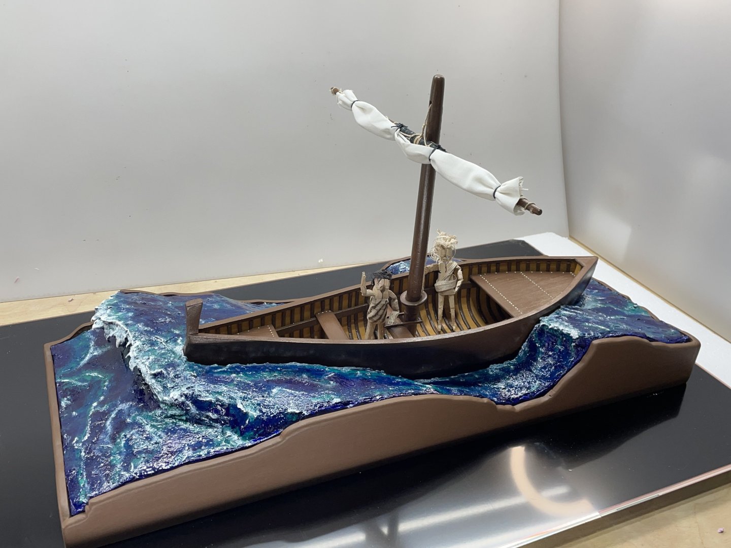


-
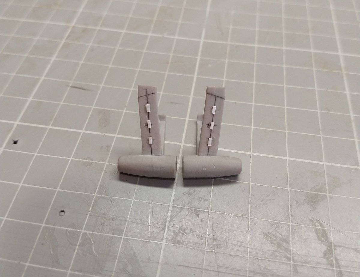
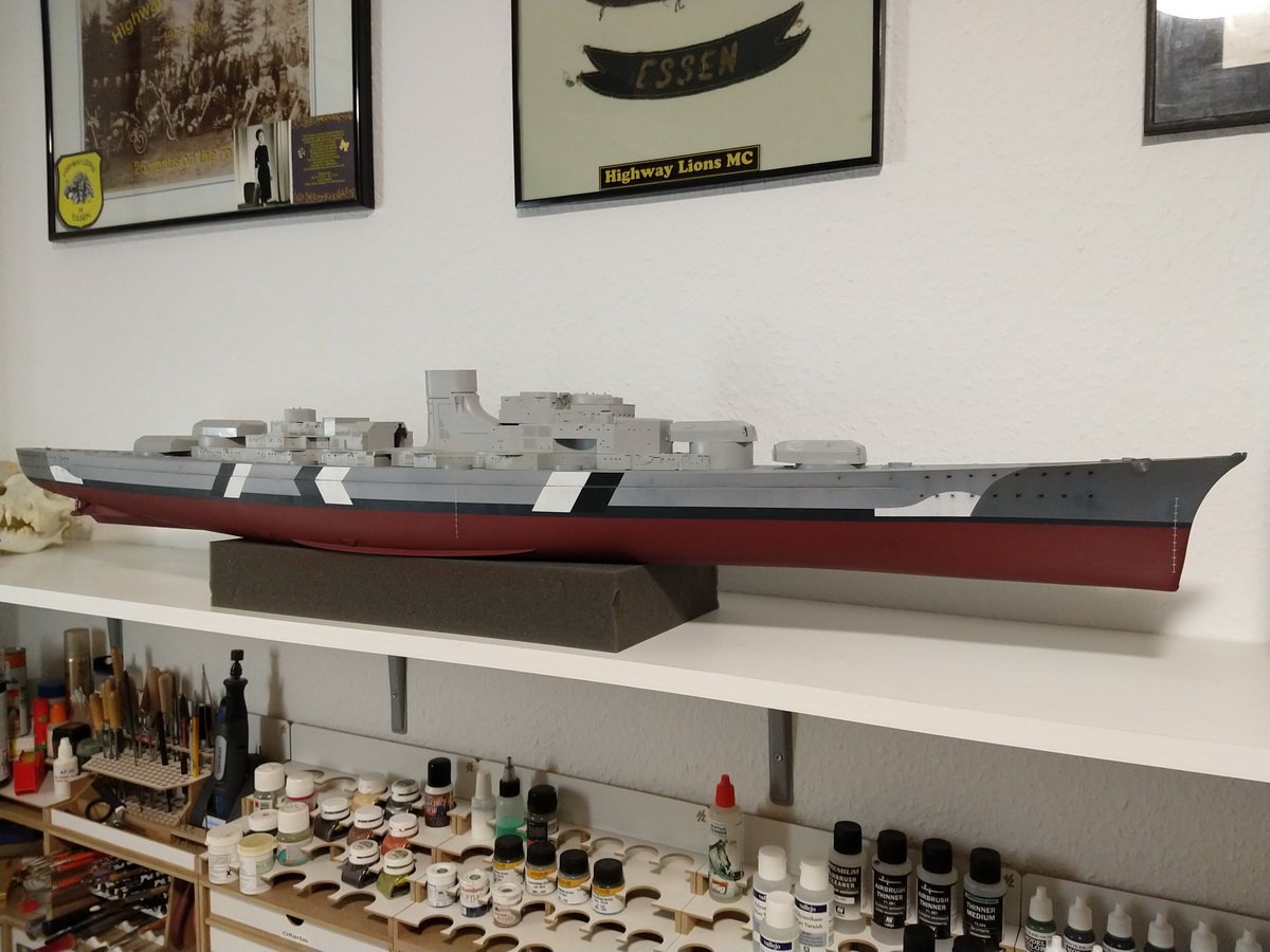
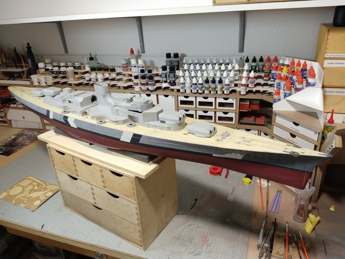
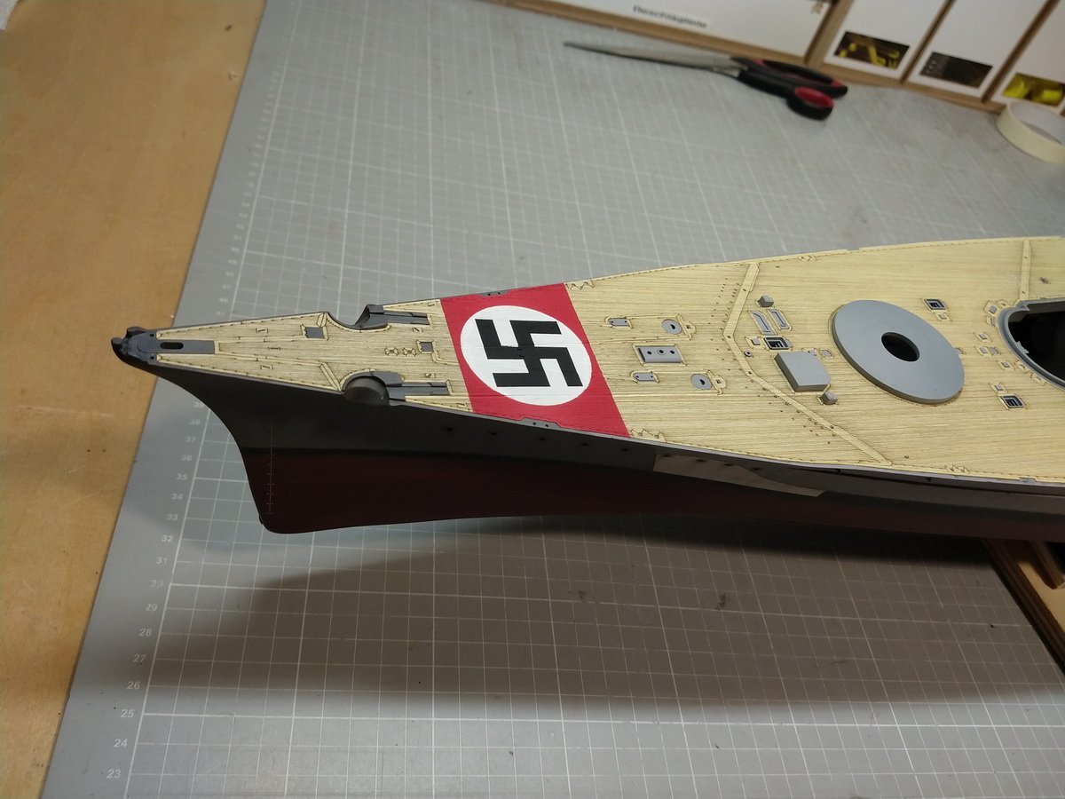
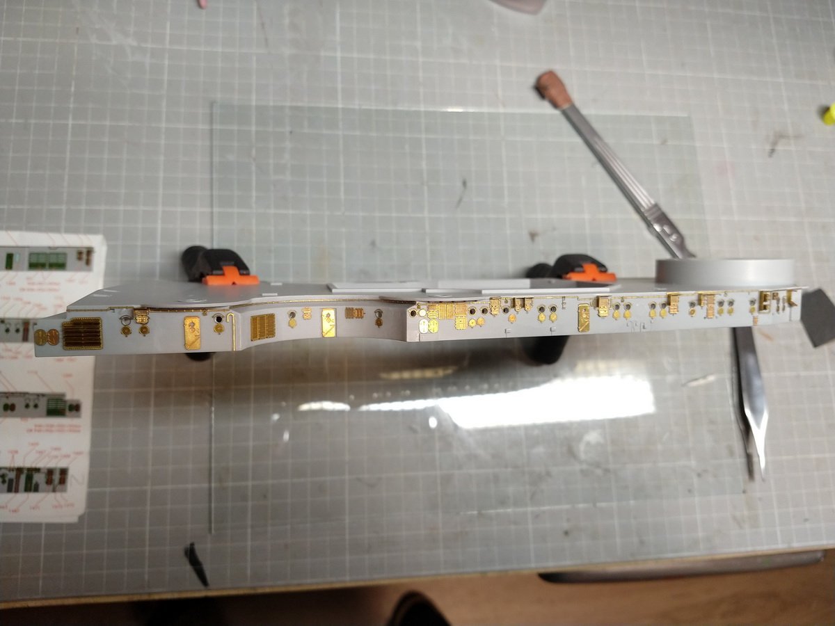
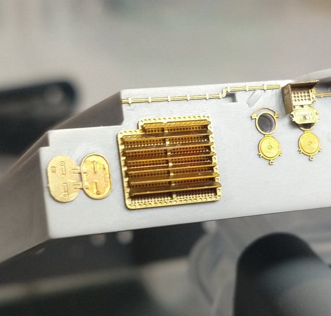
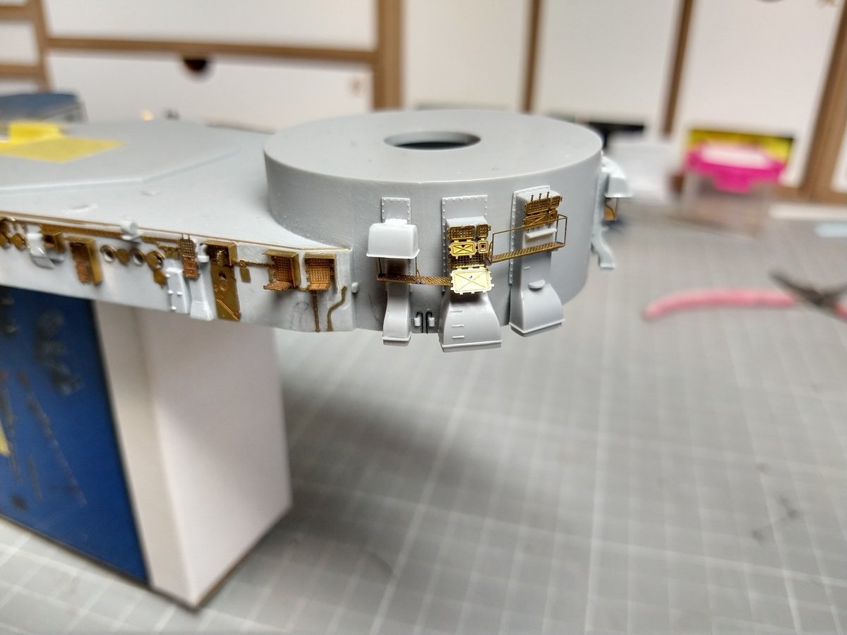
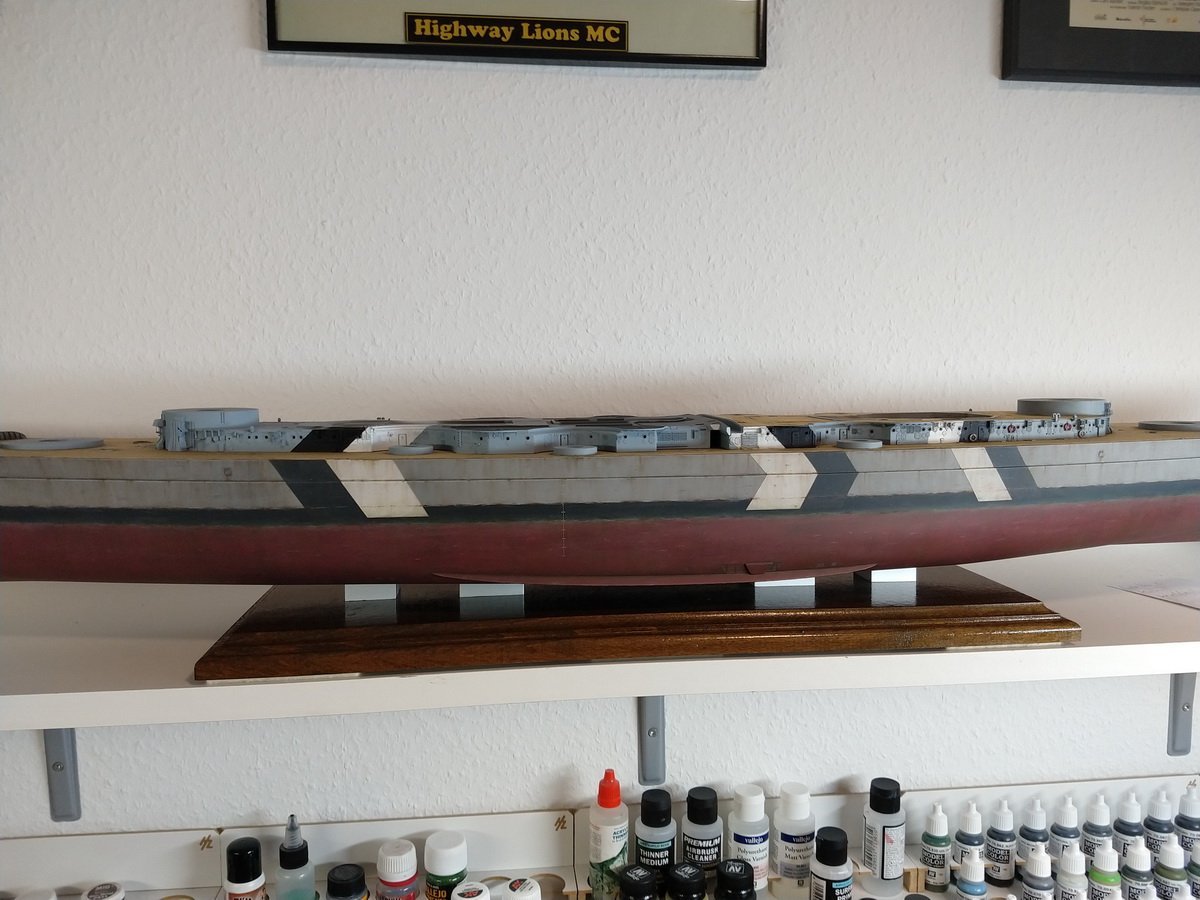
 Hello everyone, here is the construction report of my Bismarck model from the Trumpeter brand in the scale 1:200. The Pontos Detail Up Set “Advanced” is used for optimal detailing of the model. Various Veteran Models sets and all sorts of other aftermarket accessories do the rest. Not to mention a bunch of styrene profiles for scratch building and the famous leftovers box. I’m trying to create a model that shows the period from April 1941 to about 80% historically correct. I worked on the model for almost two and a half years and it was finished in October last year. This is the start: The torso needs my attention first. Portholes have to be built up and the cooling water intakes have to be added. The original kit is missing the sacrificial anodes on the shaft pants. I had decided to apply the Baltik camouflage scheme. She simply looks her best this way. But I didn't know what work there would be on the superstructure. The wooden deck of Pontos simply looks authentic. I think the deck from scaledeck is nicer, but unfortunately it came onto the market too late. Then comes the swastika in the aircraft identification, which is banned in Germany. Naturally painted, no decal. This way you can better see the grain of the wood. Then the first fine details of Pontos come onto the lower superstructure. A close-up of this fan shows the depth Pontos brings to the model. The fan details on the front barbette are just great. All sorts of missing details are added with styrene profiles and lead wire. Now the camouflage stripes had to be built on top of them. And glued to the deck. And then the ship comes to its final position, because next the rear superstructure with the deck and closes the hull Now I continued at the bow and laid anchor. Note the double bridge chains. With an aftermarket product as expensive as Pontos', you'd think they'd be included. But far from it, only normal jewelry chains are included. Greets Jölle.
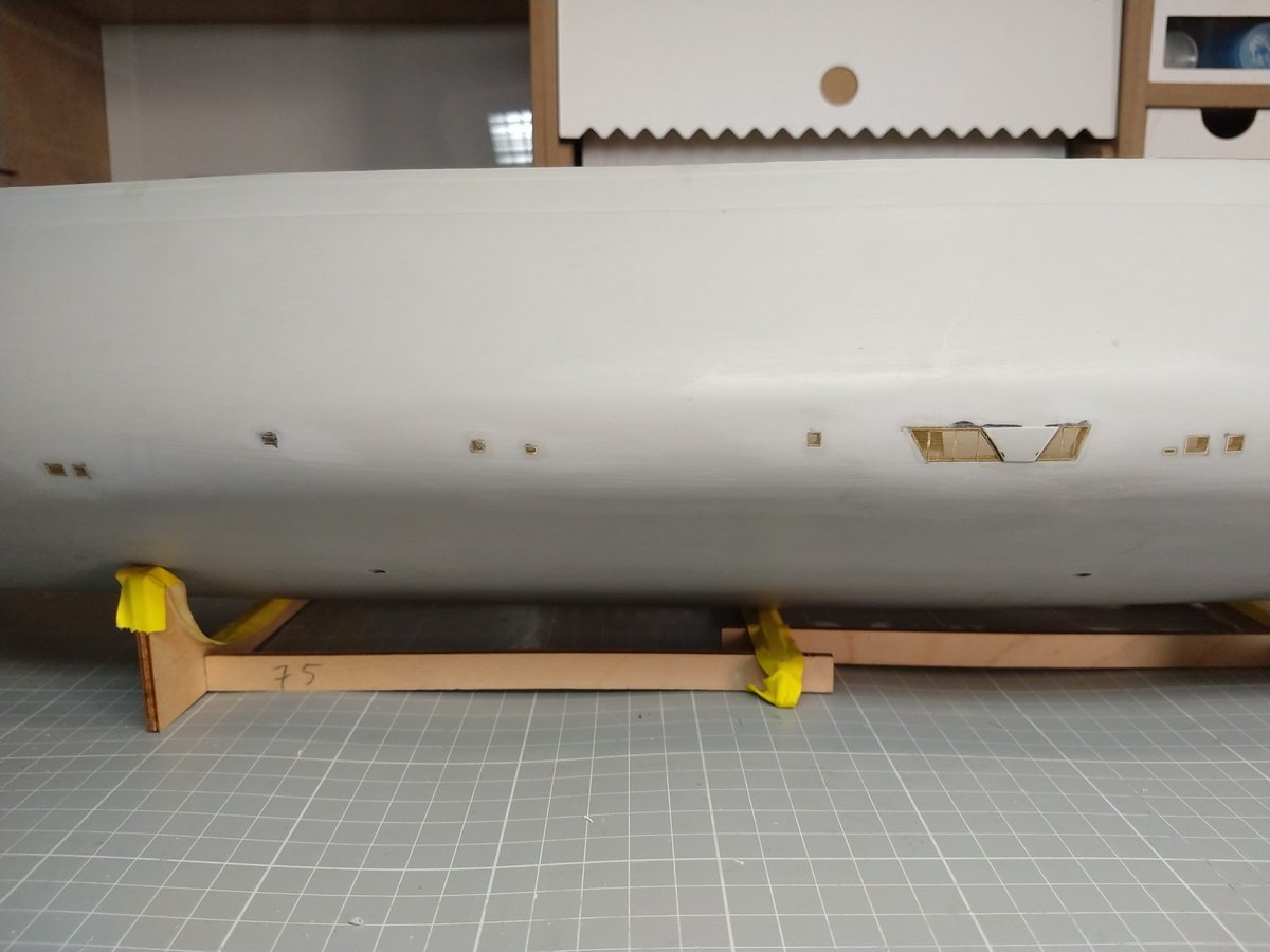
- 70 replies
-
- 10
-
-
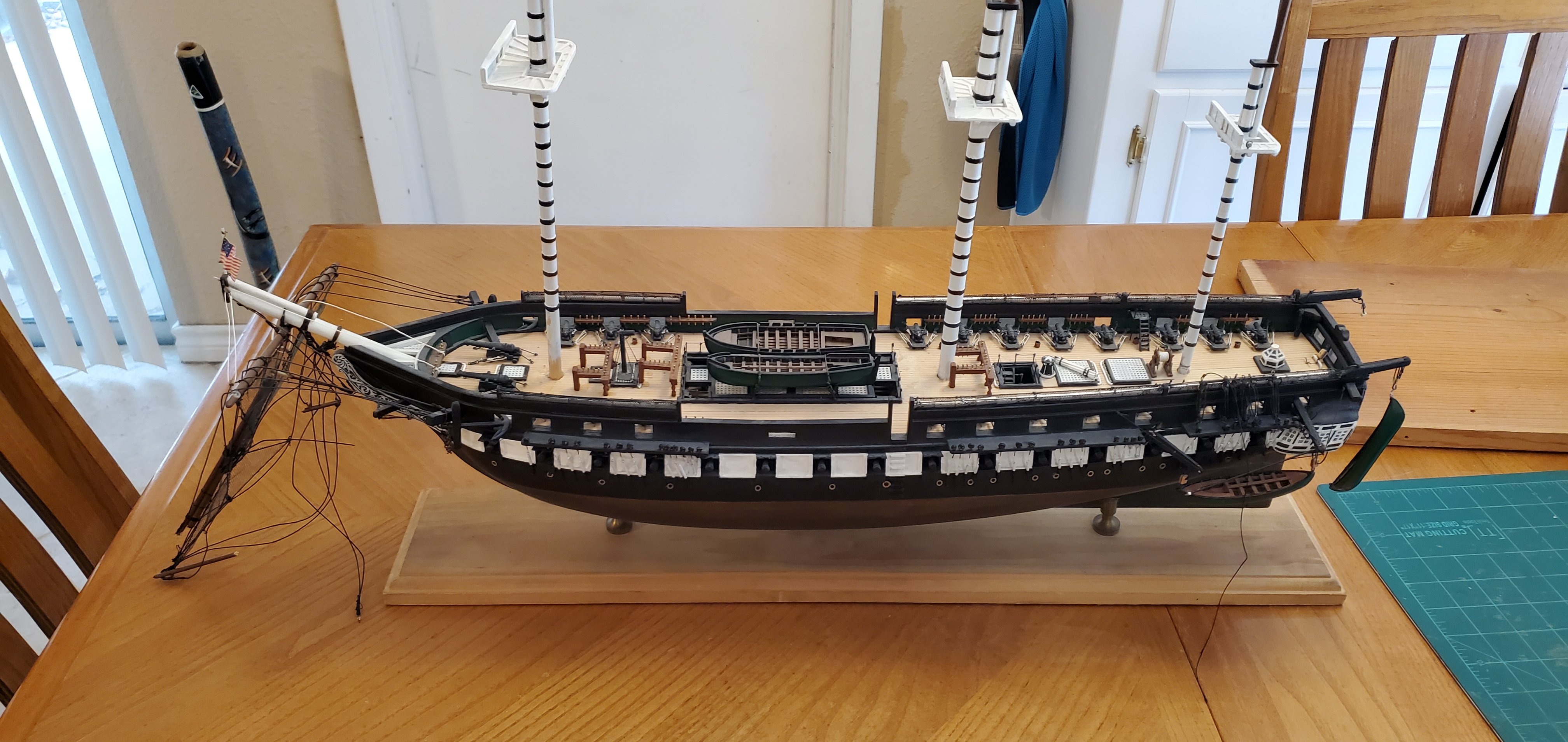
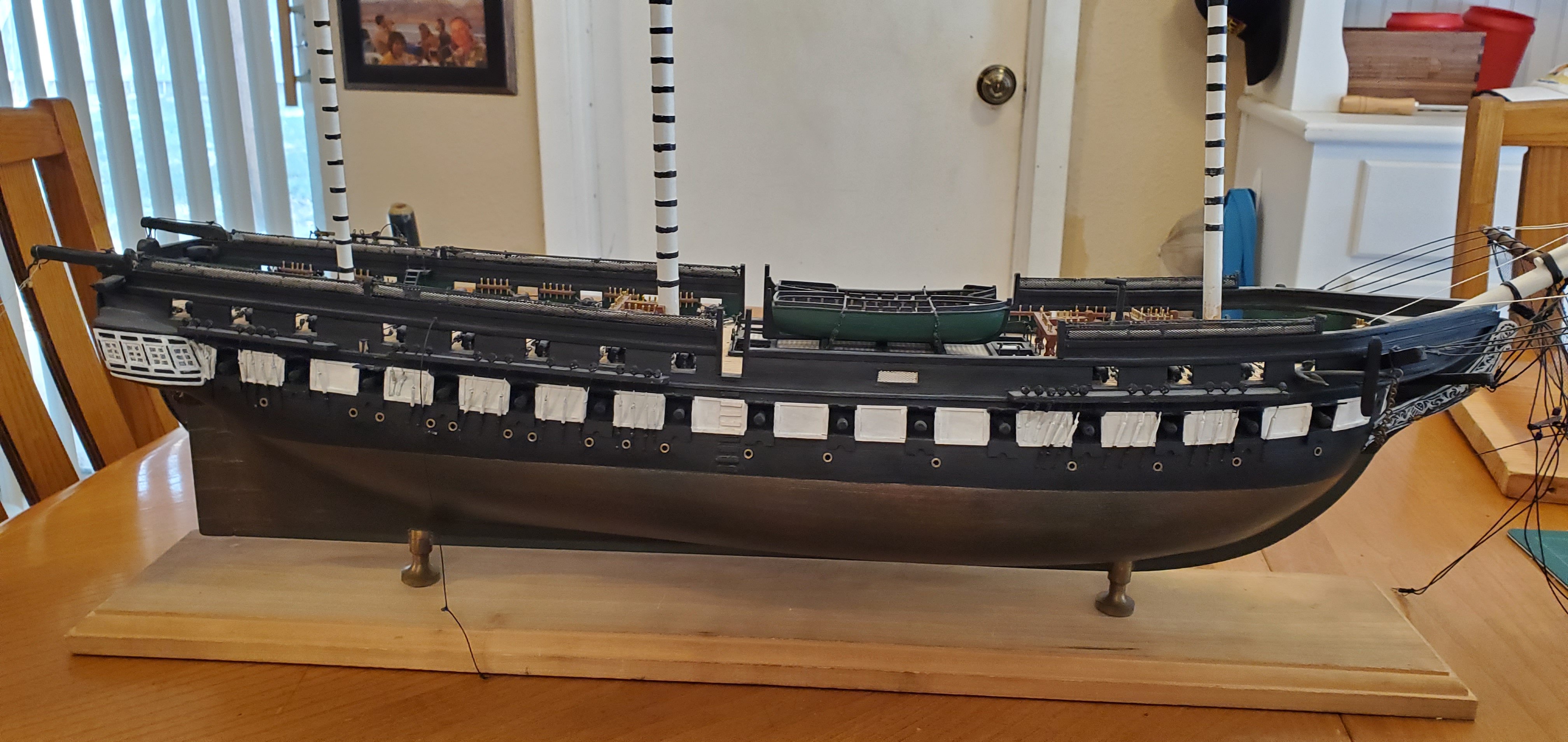
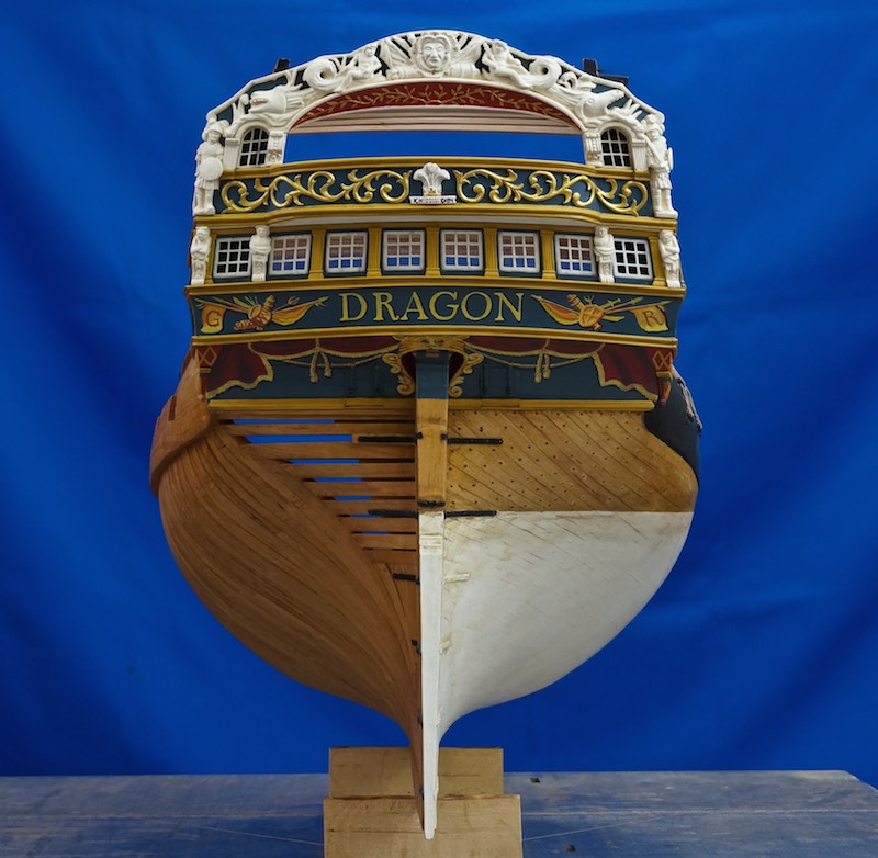
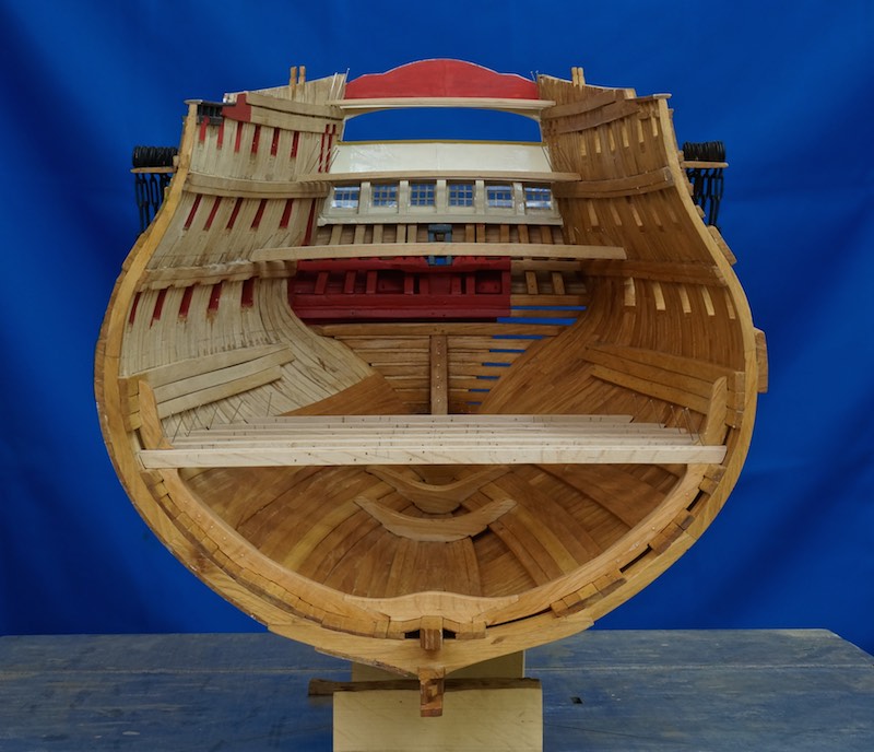
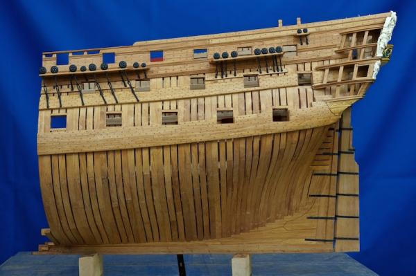
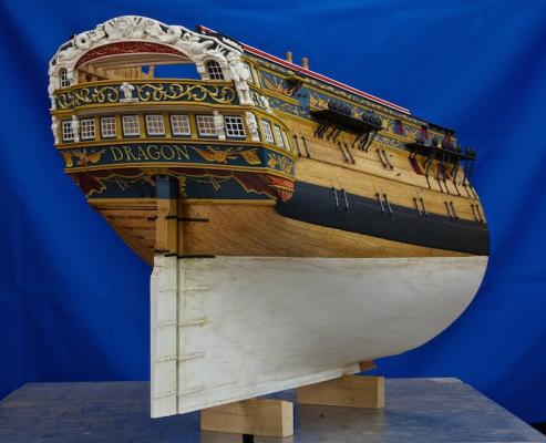
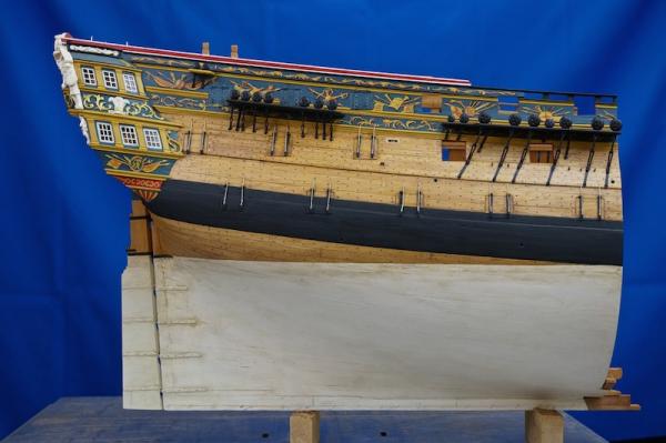
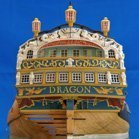 Hello everyone, after I had so much positiv response about the pictures of my model in the gallery, I decided to start a blog about this ship. About the Dragon is to say, it was a third rate ship, designed by Thomas Slade and build at Deptford. Launched 4.3.1760 and sold 1784. It is not the first ship model I have build, but the first 18th century and framed model. A friend told me about the Bellona and I'm interested to learn more about these ships. My first name is Siegfried and that name is program, Siegfried was the most famos dragon fighter here in Germany, or the only? So I would build the Dragon. I ordered the plans from the NMM and a lot of books from everywhere. Then I started learning. Because the whole ship would be too large in 1:48, I decided to build only the stern part, from the 10th frame backwards. After 3 month I started with the model. That was in the winter of 2011/12. In 2012 a friend of mine was in London and I asked him to take pictures from the models at the NMM. That was a great thing and helped me a lot. In 2013 I visited the NMM and the shipyard at Chatham. Here I saw the Superb, the third ship of the Bellona class. That visit changed a lot, you will see it in the pictures. I changed mostly the color of the hull. I will post the first pictures in a fast pass, to get update with the actual level of work. And please excuse my english. Regards, Siggi
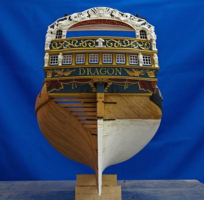

- 453 replies
-
- 35
-
-
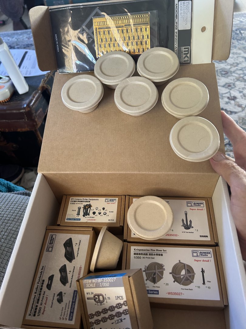
 I’ll add the link where I did this build here 10 years ago, this time I own and airbrush and 3d printing is a thing. I’m still very happy with the old one and I intend on doing this build as a part of my presentation for our local hobby show in November which as become one of the biggest shows in Australia. I also have access timo the Australian War Memorial which has relics of her. the kit is now super hard to find and stupidly expensive on EBay with shipping anything outside of the US about $70 (that’s just saying we don’t want your business )
- 76 replies
-
- 11
-
-
- Micromaster
- Eduard
- (and 4 more)
-
 I know I've got some other things in progress, and a couple of them are paper/card models. But, I've been trying to promote card model products for Ages of Sail, and I finally couldn't stand it any more, so I broke down and bought one of Shipyard's laser-cut card kits that I've been eyeing ever since it came out. In this case, it's Shipyard's 1/72-scale laser-cut card kit of the 10-gun snow-rigged (brig) sloop, HMS Wolf, 1754. Now, this has been something of a "closet" project, in that I hadn't posted any build log details, though I've been working on the kit since July 23. So, I'm going to maintain on this first page, an up-to-date photo of the build. Then, I'll go back to the beginning and share my build details from there, working my way forward. Someday, there will be a great convergence in the Universe, you will all feel a strange shift in the Force, and the build log will get caught up with the build... Photo taken 9/23/22: I bought Shipyard's 1/72-scale HMS Wolf kit from Ages of Sail. Officially, the US Distributor for Shipyard products. Yes, I do some work for Ages of Sail, and this build just shows how dangerous that situation is for me. But, I also build some things to make myself better acquainted with the products. At least that's my excuse for some of my partial builds. This build, however, has been so much fun and it's come along so nicely that I'm really looking forward to completing this model. In order to simplify this build log, I posted all my components photos into a kit review, which you can now find here:
- 105 replies
-
- 14
-
-
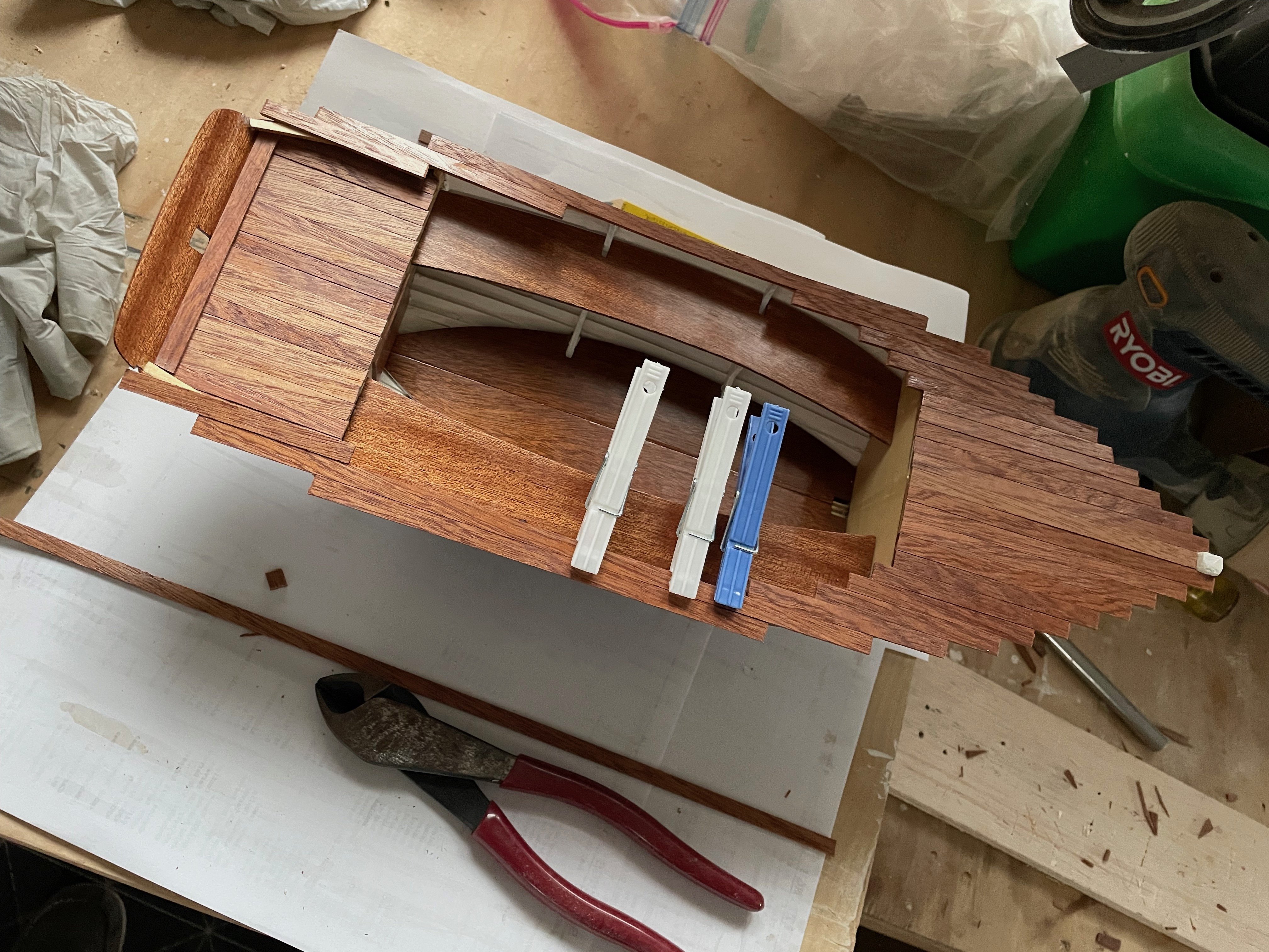
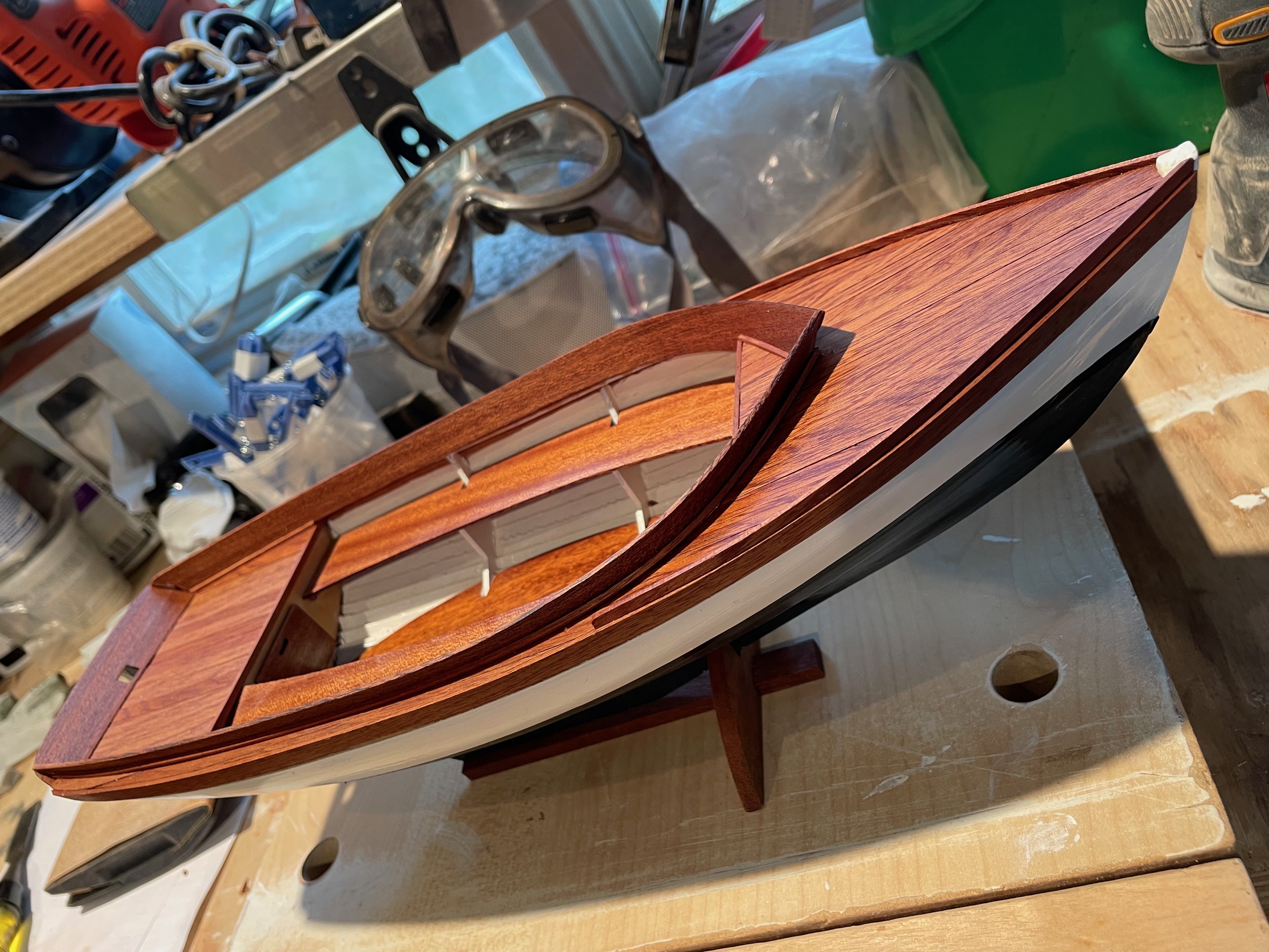
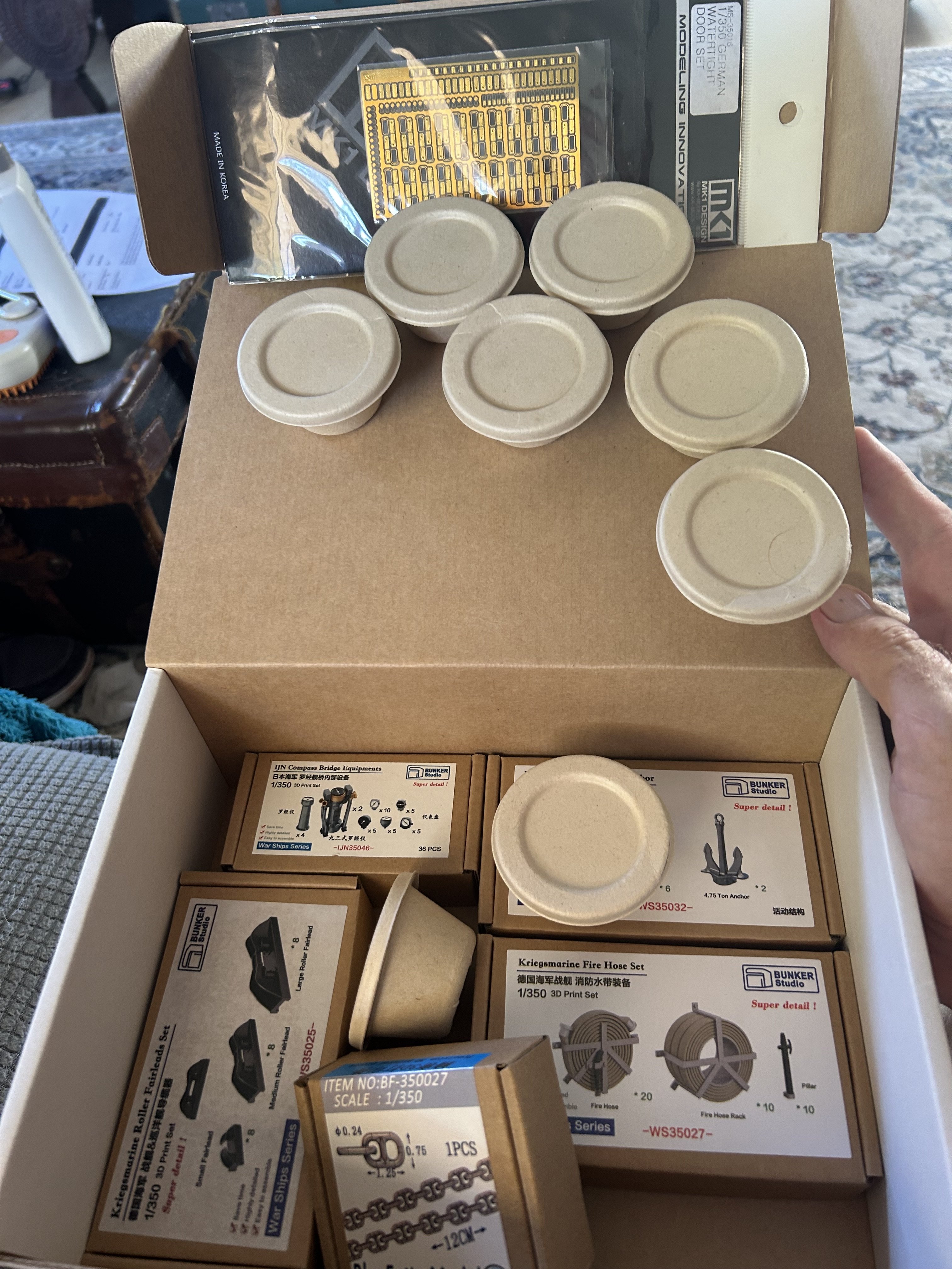
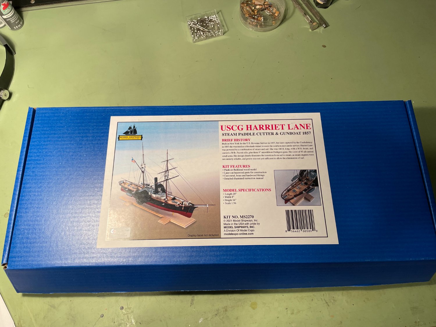
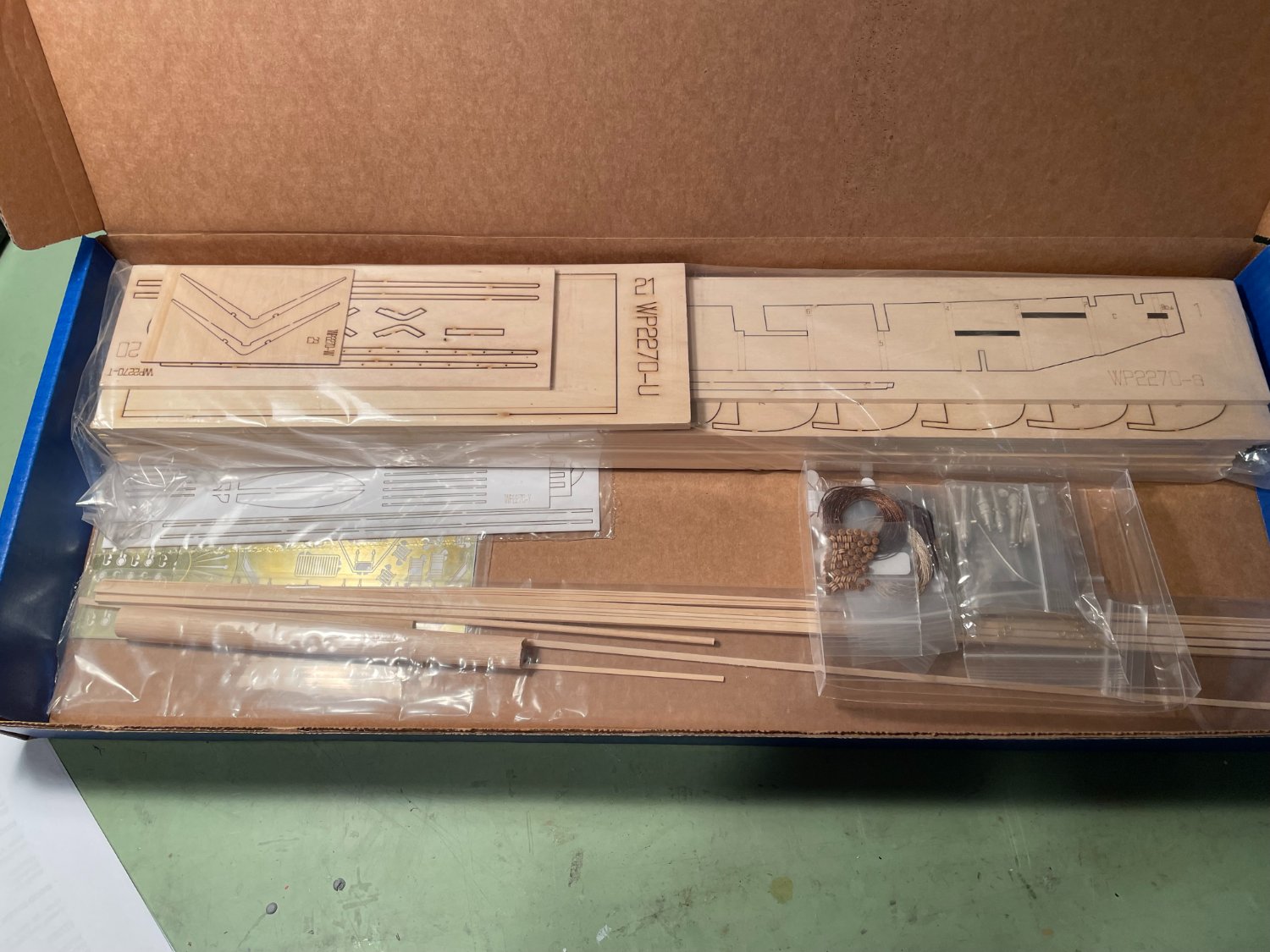
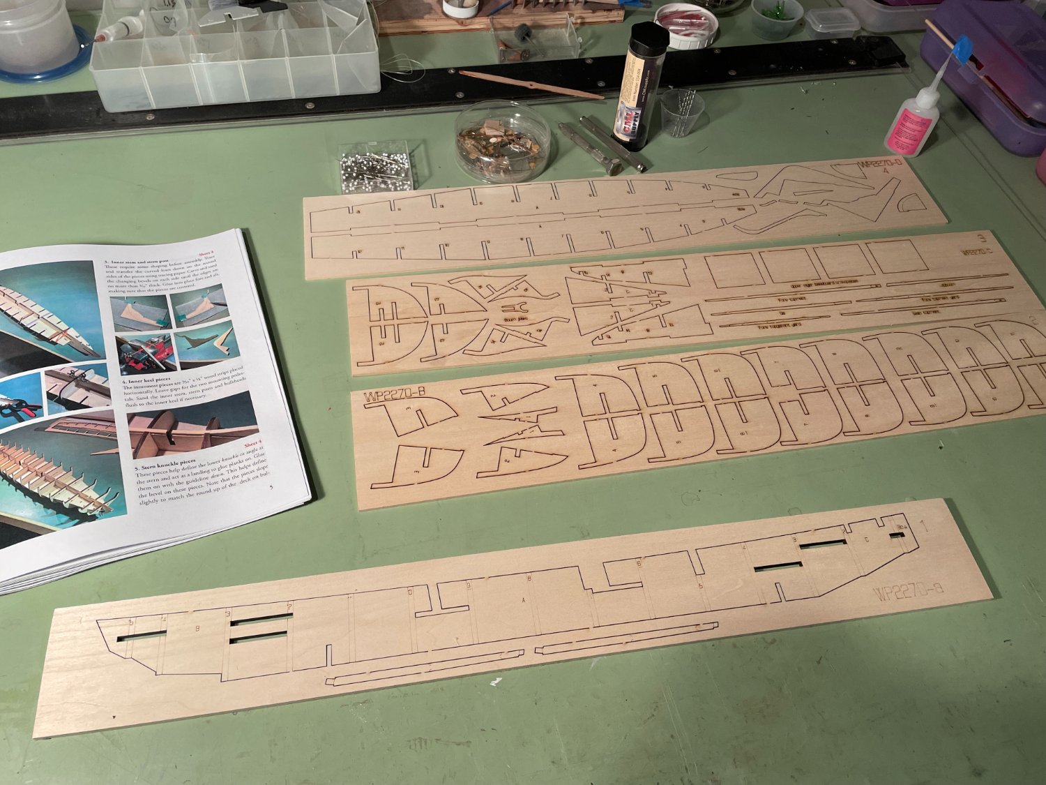
 Hello all. I have some time I my hands so I thought I would do a build log of the USCG HARRIET LANE that I got as a Christmas present (to myself). I wanted to try something a little different so the combination of paddlewheel and sails appealed to me. I’ve been away from MSW and the NRG for a few years and had always liked the forum discussions and model postings so I thought I would give it another go. The model’s scale is 1:96 (⅛" = 1' 0") and the overall length will be 28", width 8", height on base 16". The model was designed and instruction book was written by David Antscherl. The kit is from Model Shipways and was purchased from Model Expo. Description of the ship from the instruction book. The Harriet Lane was 177' 6" long and 30' 6" wide, with a 12' 0" depth in her hold. Her mode of power was provided by double marine steam engines driving two side paddles, as well as two masts for sailing. When launched, her armament was described as ‘light guns’. However, when she joined the West Gulf Squadron her firepower was increased. She was given a 4" rifled Parrott gun and a 9" Dahlgren forward, with two 8" Dahlgren Columbiads aft. Her full crew complement was 95. Launched in November 1859, she was named for the niece of President James Buchanan, who was unmarried. Harriet acted as his First Lady. Mandatory pictures of the box and contends.

- 144 replies
-
- 8
-
-
- Harriet Lane
- Model Shipways
- (and 1 more)
-
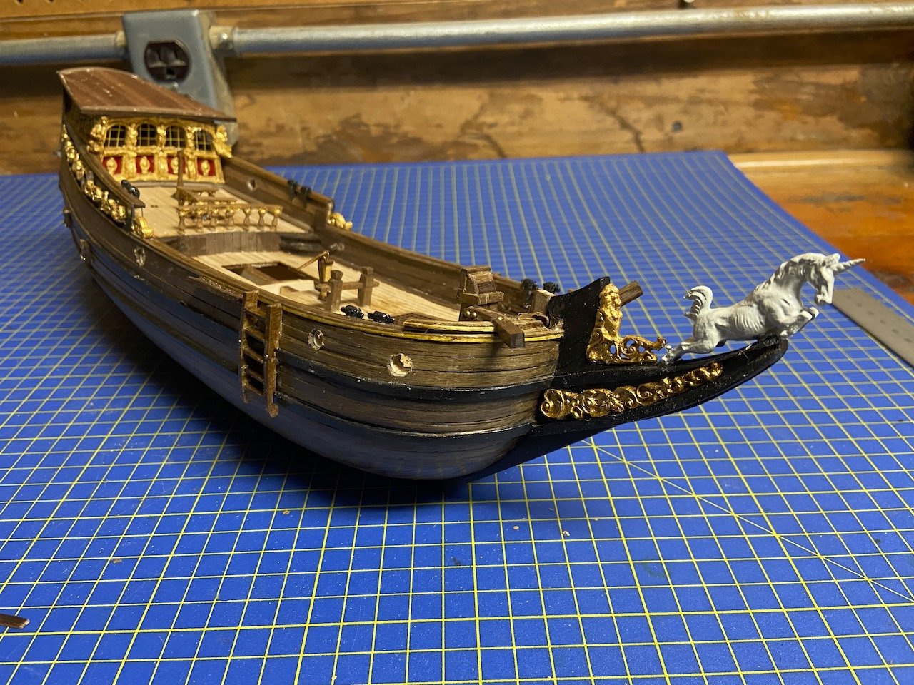
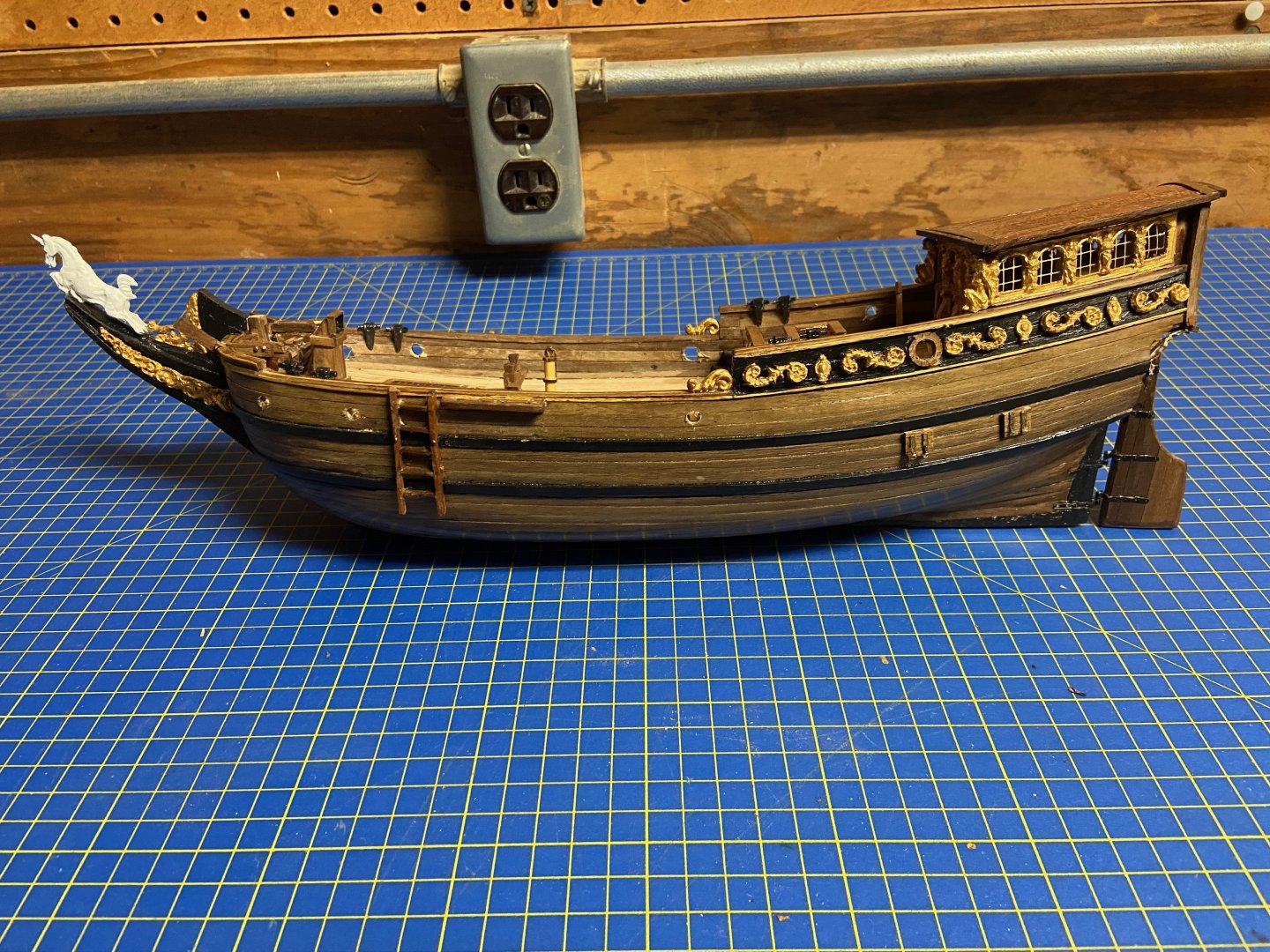
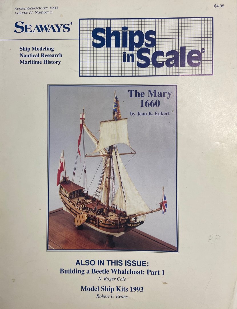
Those following my HMS Wolf card model build may be wondering where I disappeared to. So this is what I've been doing for the past couple months. A couple years ago, I bought a Mantua/Sergal Sovereign of the Seas kit, unstarted, at an estate sale. I guess the sellers were so happy to move the kit that they threw in a partially started Amati Prince (yes, the rare, and huge Amati Prince in the wooden box), and this partially completed Yacht Mary. Having recently completed Woody Joe's Charles Royal Yacht, and having so enjoying modeling a royal yacht, I was interested in working on this new acquisition. But, the model left my possession for another modeler to work on. But, over time, I thought about how the original builder, a Mr. Richard Fletcher who lived up near Placerville, CA, was building this as a wedding present. I didn't know the man or the details of who it was supposed to be fore, but I didn't know that the builder's widow really wanted to know that her late husband's models were being continued. Later on, finding out that the modeler I had passed this onto was turning into some random fantasy ship, I decided to try to rescue it, with the intent of finishing the model and presenting it back to the Mr. Fletcher's widow. So, with my new plans, I managed to get the model back, and start working on it. My intent is not to make a perfect model of the Mary, nor a perfect model of a Dutch yacht. Rather, it's to essentially take Richard Fletcher's work and to continue the model to completion without changing too much. That's not to say I would avoid ANY "corrections" to the build, but mostly to avoid changing the nature of the model more than I need to. While I don't have any photos of the model after it came back into my possession, I did have to clean up some alterations that were done to it, such as the removal of a "poop deck" railing that was installed for the fantasy model, and a couple other minor things that had been broken since I saw it last. Aside from that, I noticed the original builder had some trouble with a few things and left a big gap just between the transom and the gallery windows casting. So, I did a few small modifications to make the model look better. By the way, I've always been interested in modeling the Yacht Mary, and even have an unstarted, original Mamoli kit, which gave me access to the original, full-sized kit plans, which I found helpful. I think my interest in the model dates back to seeing the late Jean Eckert's build in the old Seaways' Ships in Scale magazine. She, by the way, started and ran the South Bay Model Shipwrights club that I'm a member of still today. I'll post a series of photos later to show the progress to date. I'm hoping to complete the model by June. So, this will not be a long and detailed build log. Mostly just wanted to be able to share about the work. Note: I will be getting back to my HMS Wolf build shortly!
- 82 replies
-
- 11
-
-
- Yacht Mary
- Mamoli
- (and 1 more)
-
 Young America - extreme clipper 1853 Part 1 - Decisions I took most of the summer deciding whether I would undertake another ship model and if so, what the scope and subject would be. I had a lot of time to think about this while catching up on neglected home maintenance and repair projects. After deciding that I needed the challenge of another ambitious project, the decisions on scope and subject kept me busy through July. I also had to decide whether I could commit to another Naiad-like build log. We shall see. I received a number of suggestions on subjects and that input is most appreciated. Since I expect this project to span a number of years, the decision was a big one. I have enjoyed wrestling through the process of deciding. I had a number of criteria: 1) significant design/drafting content, 2) fully-framed construction to further explore my interest in structures, 3) a change from the well-trod path of fully-framed 18th Century Royal Navy subjects, 4) avoiding commonly modeled ships, and 5), I thought it was time to do an American ship. Before focusing on the extreme American clippers, I considered, among many other possibilities, a 19th Century American warship, perhaps steam-sail, and looked seriously at some of the ships by John Lenthall, built locally at the Philadelphia Navy Yard – examples: Germantown (sail), Princeton (screw/sail), Susquehanna (paddle/sail). In the end, the idea of the extreme clipper was too attractive to dismiss. To me, this type represents an apex of achievement in wooden sailing ship design and construction – in terms of sleek hull lines, sailing performance, structural development and sheer beauty. In the design of the extreme clippers, minimum tradeoffs were made to the one paramount design parameter - achieving the shortest sailing times between far-flung ports. Speed meant not only sleek hull lines and a spread of canvas, but also the strength to withstand continuous hard driving, day-in, day-out. After deciding on the clipper – and an American (meaning all wood) clipper - I chose the work of William H. Webb of New York. It would have been easier to select something from his more popular competitor, Donald McKay, but McKay’s ships built at East Boston, have long been widely modeled – Staghound, Flying Cloud, Lightning and others. McKay’s papers do include substantial structural detail – very tempting. Webb, too, has left papers, and these have been explored, with information published in the secondary sources I have used. There are many gaps, but there is a family resemblance in details to all these ships and many practices and scantlings were commonly adopted. Webb presented more of a challenge – in more ways than one – as I will describe later. Of Webb’s ships, I chose Young America, built in 1853, his last extreme clipper. Less is known about her construction than some of his others, so the task of piecing her structure together is more interesting. I will discuss this, the ship, and the extreme clipper era in the next posts. Below is a photo of Young America, docked at San Francisco, a frequent port of call for her. She was built mainly for the East Coast to California trade. In the picture she is rigged with double topsails - a modification from her original single topsail rig. There are also some paintings of her. She was considered Webb’s masterpiece – one of his twelve clippers in a list that included renowned ships like Challenge, Comet, Invincible, Flying Dutchman – all of these examples being 200 to 240 feet in length. YA enjoyed a thirty-year career that included fifty passages around Cape Horn. She set a number of sailing records and earned a ton of money for her various owners – and for those who made money betting on passage times. In 1883 she left Philadelphia carrying 9200 barrels of Pennsylvania case oil, cleared Delaware Bay and was never heard from again. The model may be fully rigged. I will decide later. With the hull length involved (240’) the scale is likely to be 1:72, but that is not yet cast in stone. Structural drawings are well along and I expect to start construction later in September. I hope these posts will be of interest and perhaps draw some attention to this somewhat neglected modeling genre. Ed
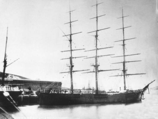
- 3,612 replies
-
- 28
-
-
- young america
- clipper
- (and 1 more)
-
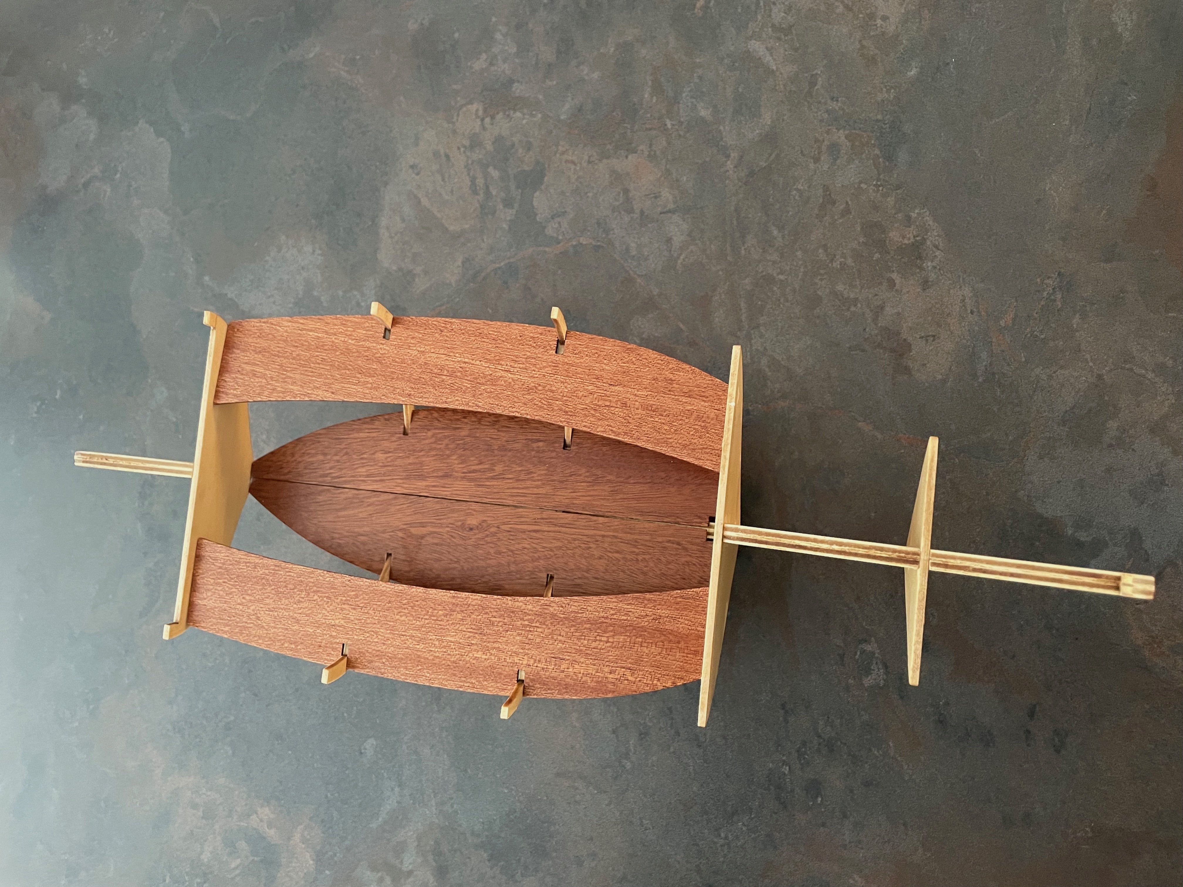
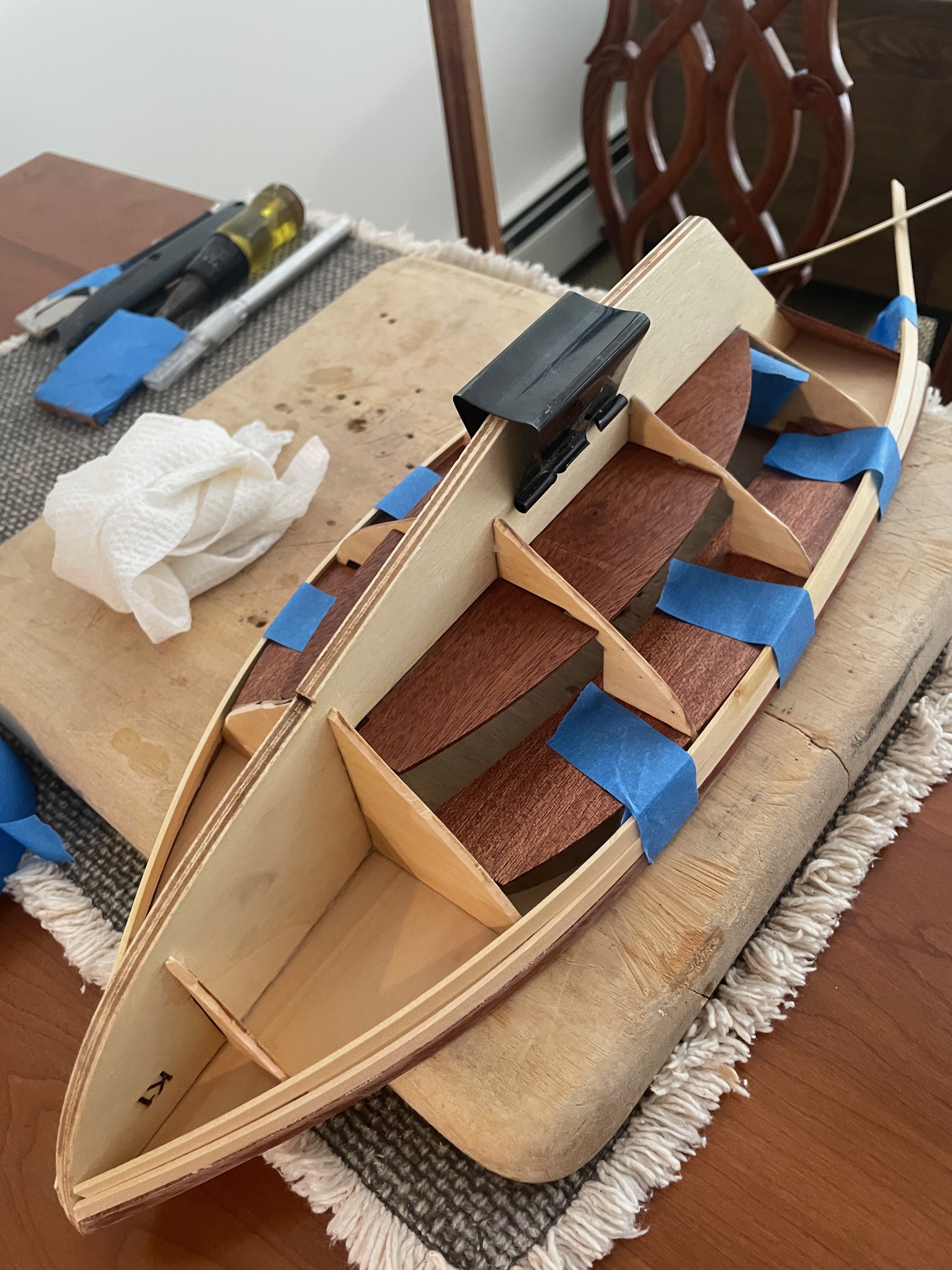
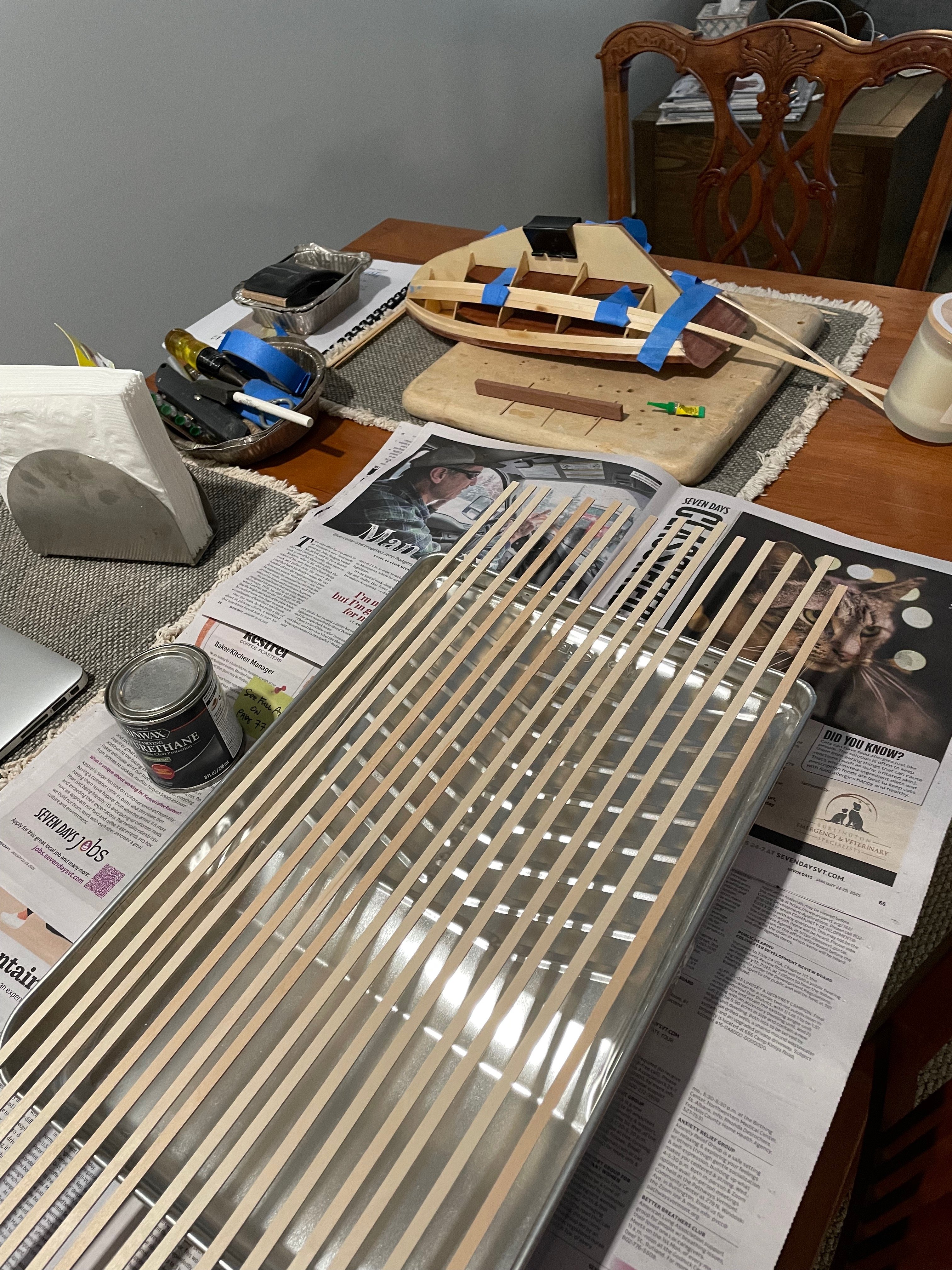
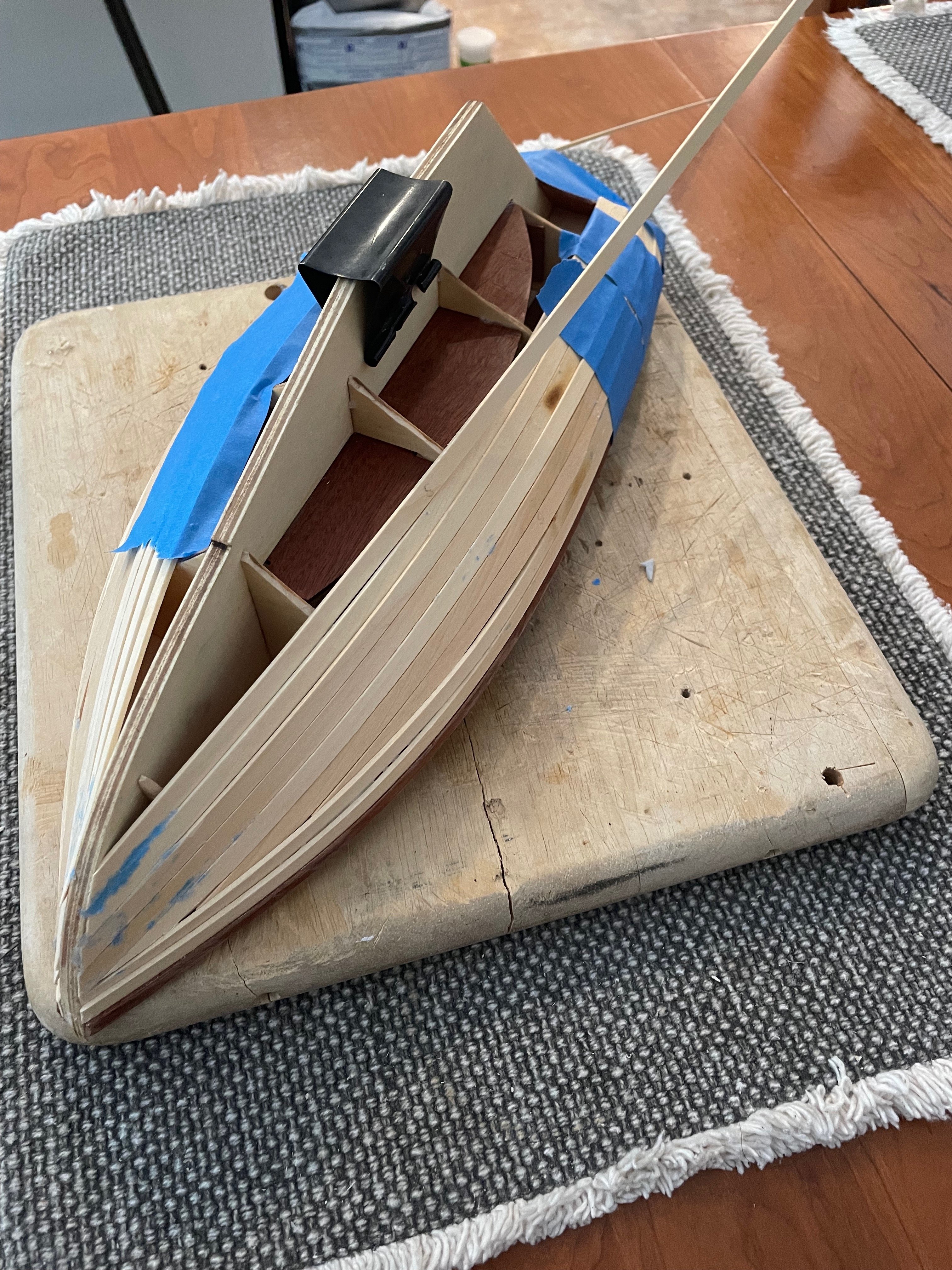
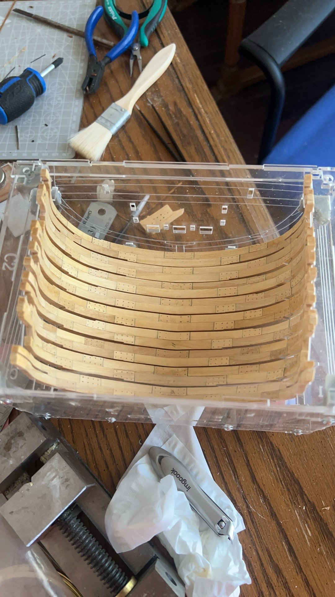
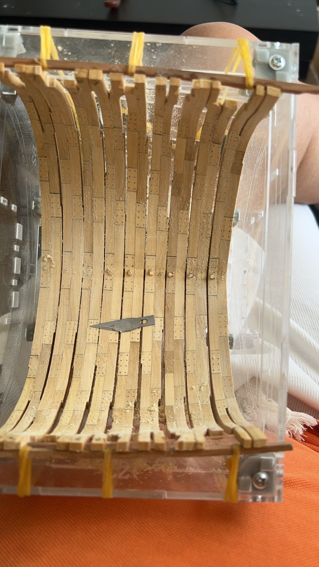
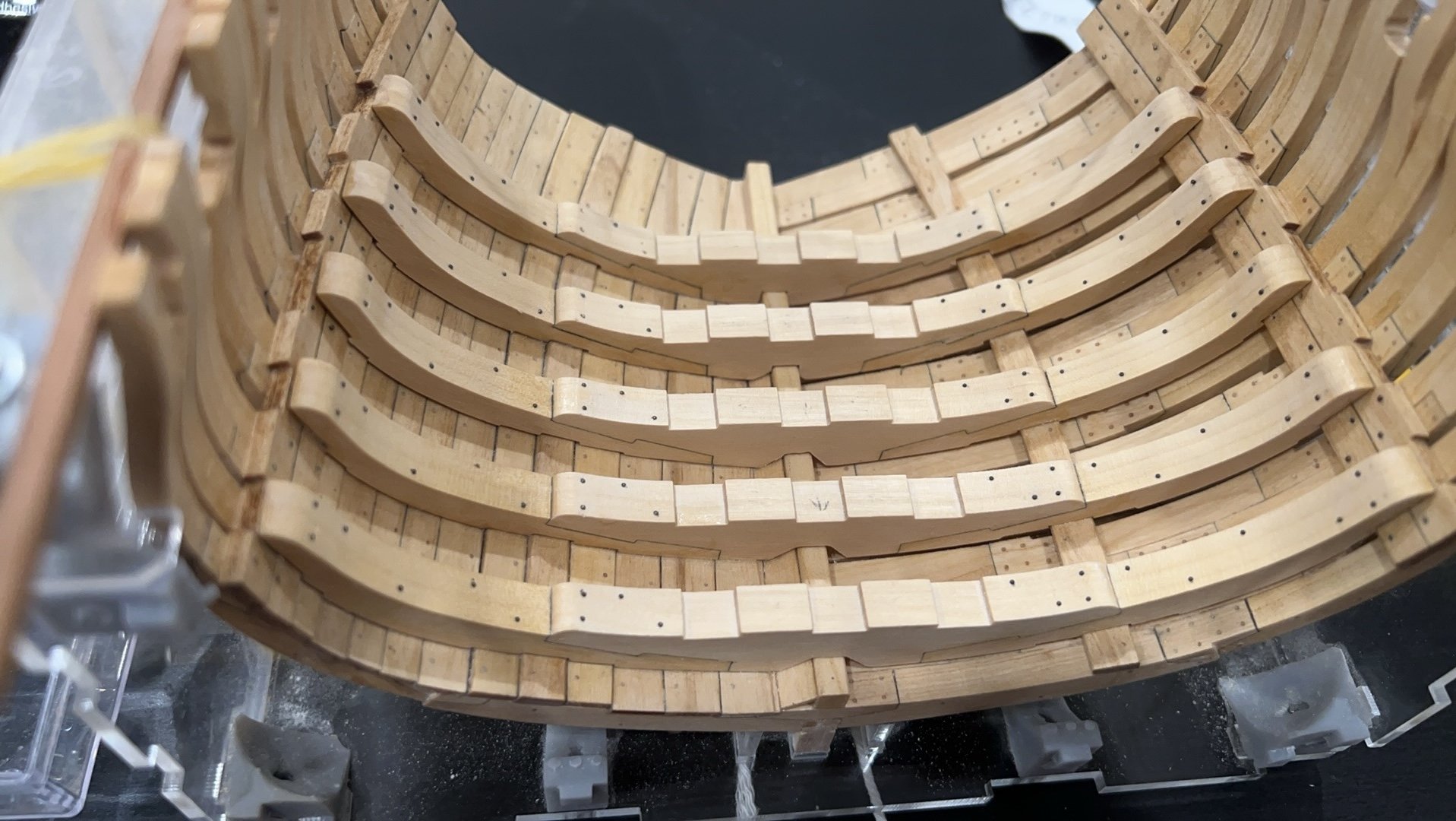
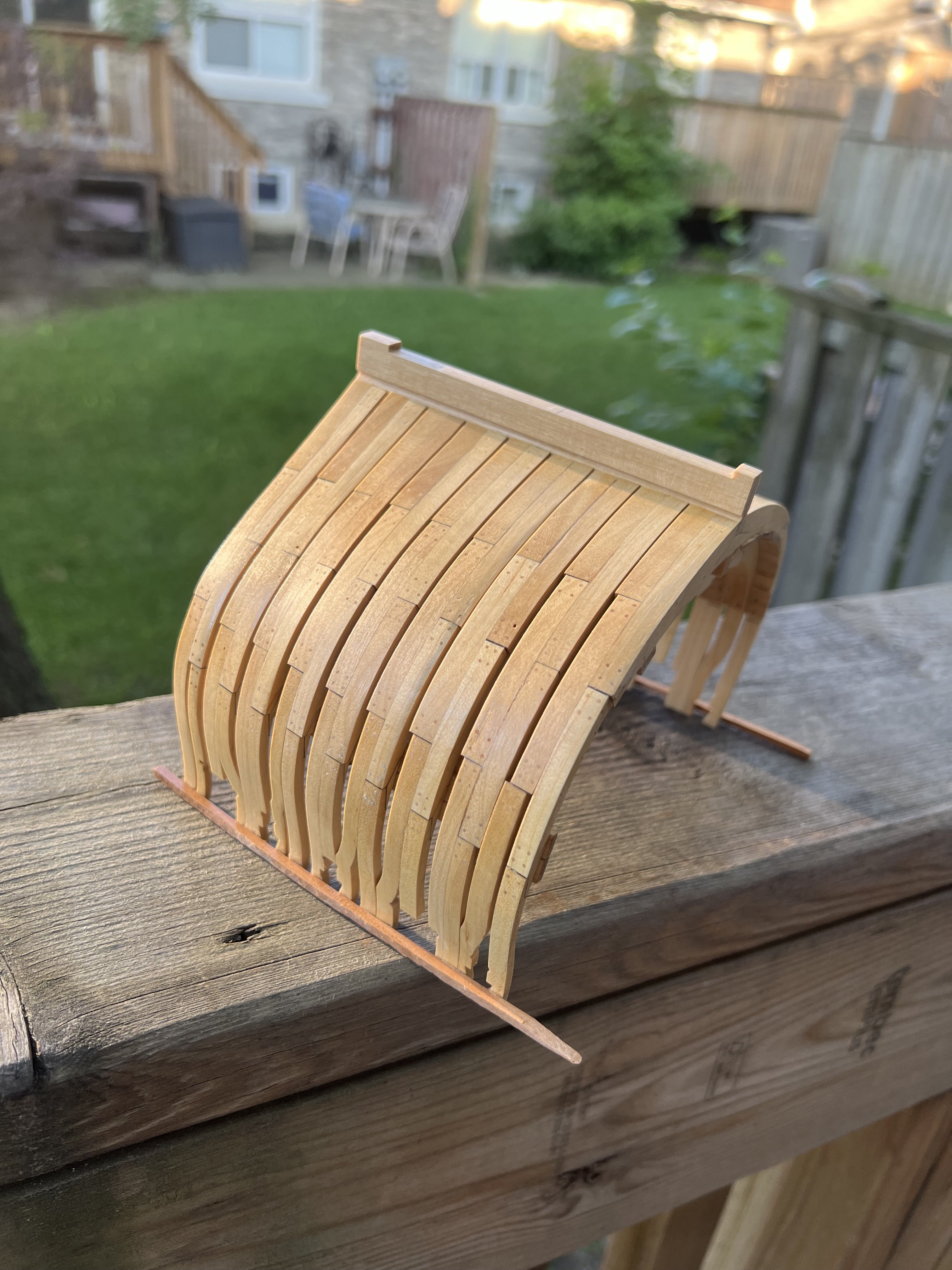
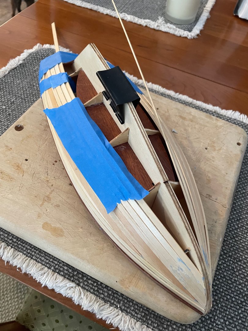
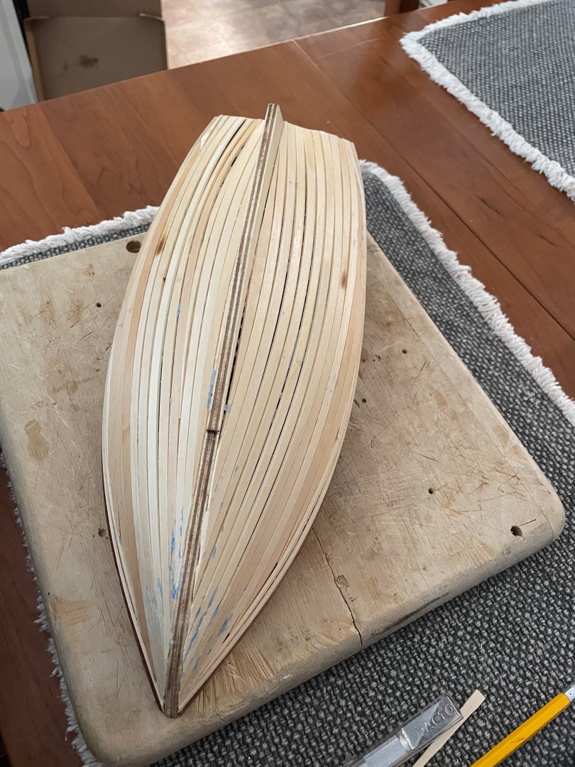
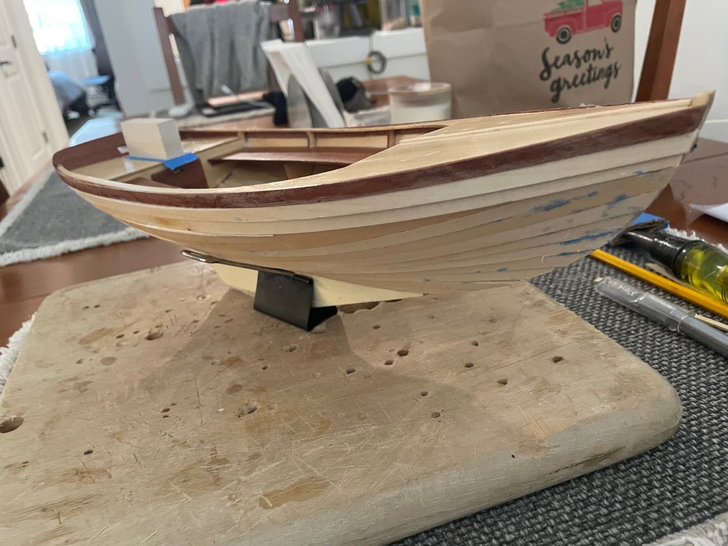
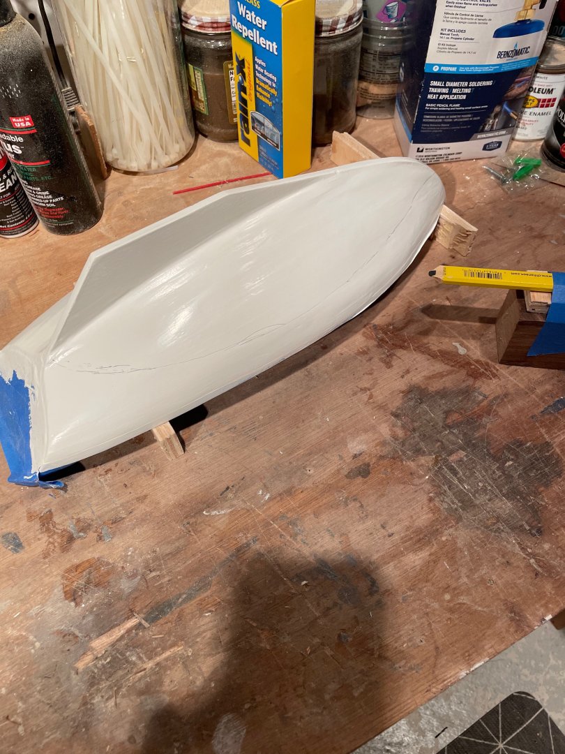
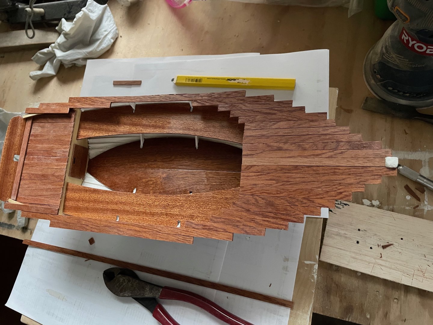
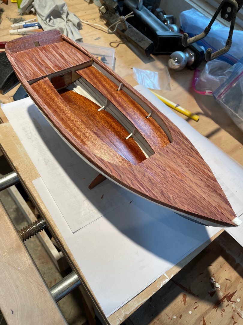
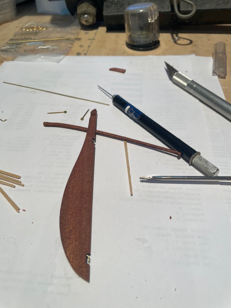
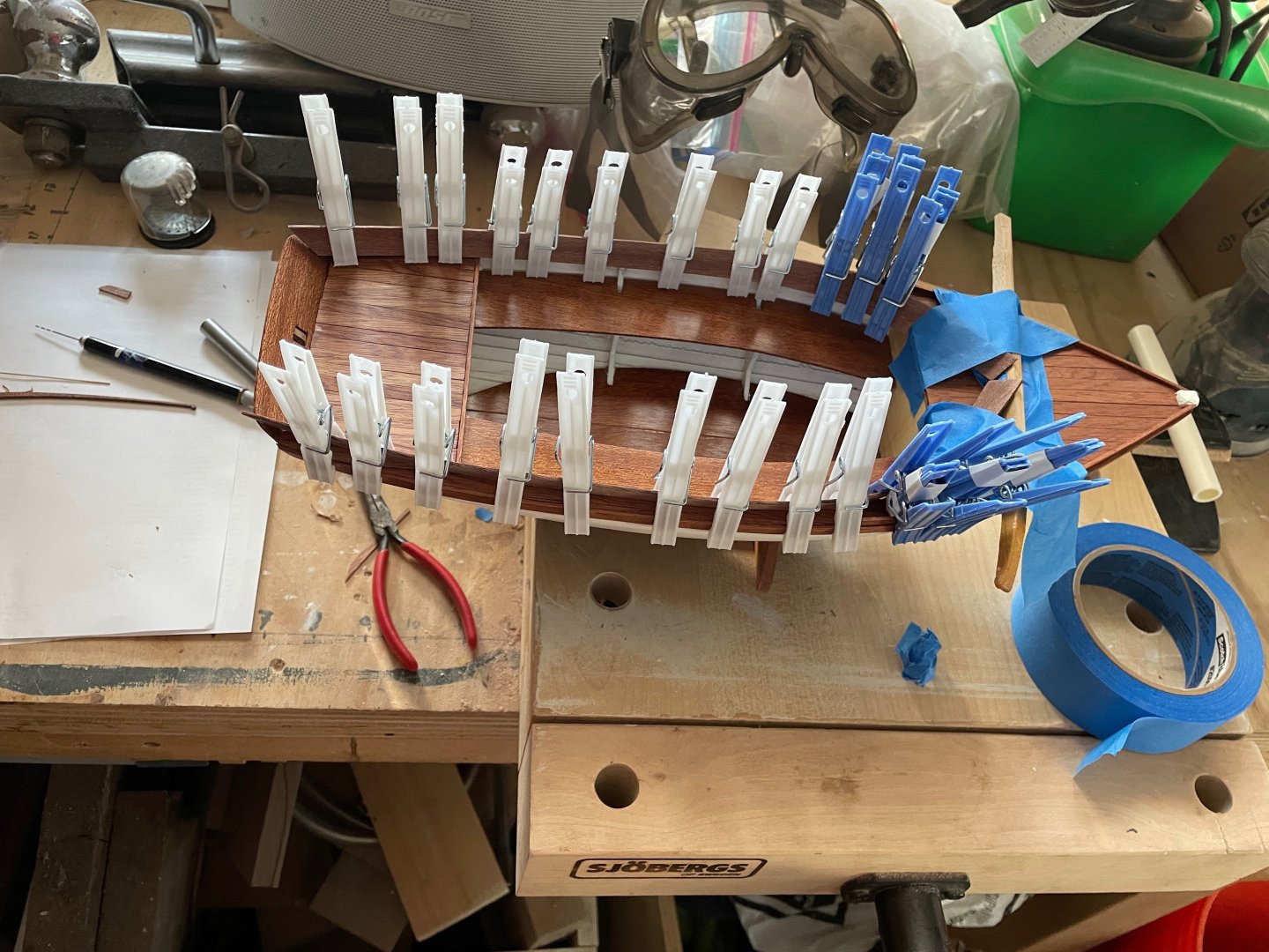
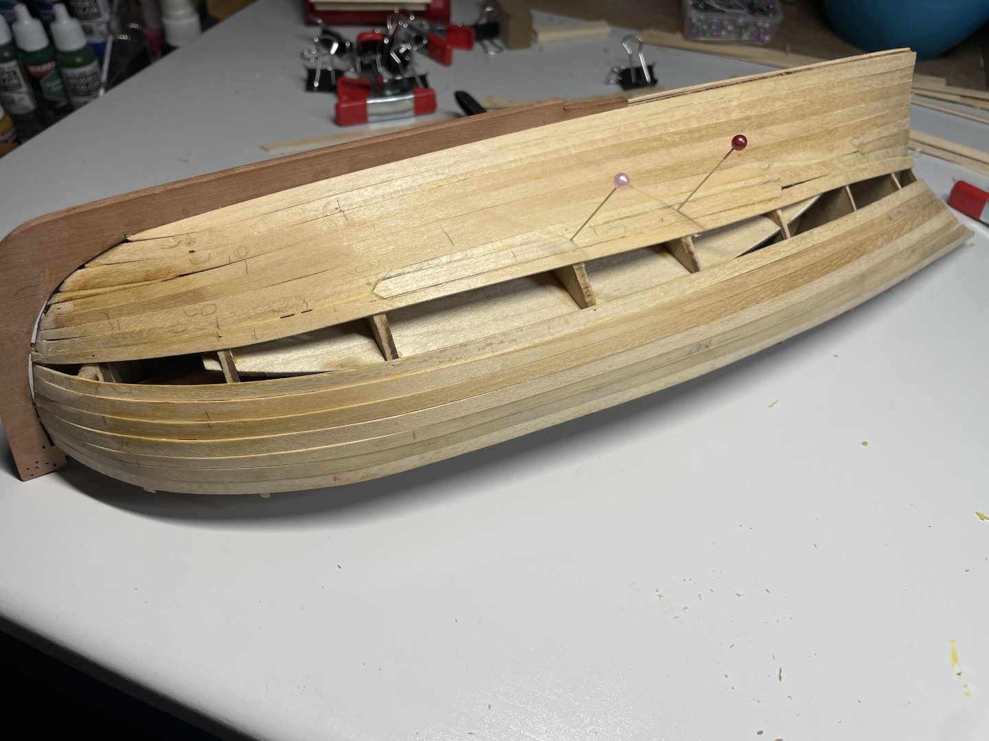
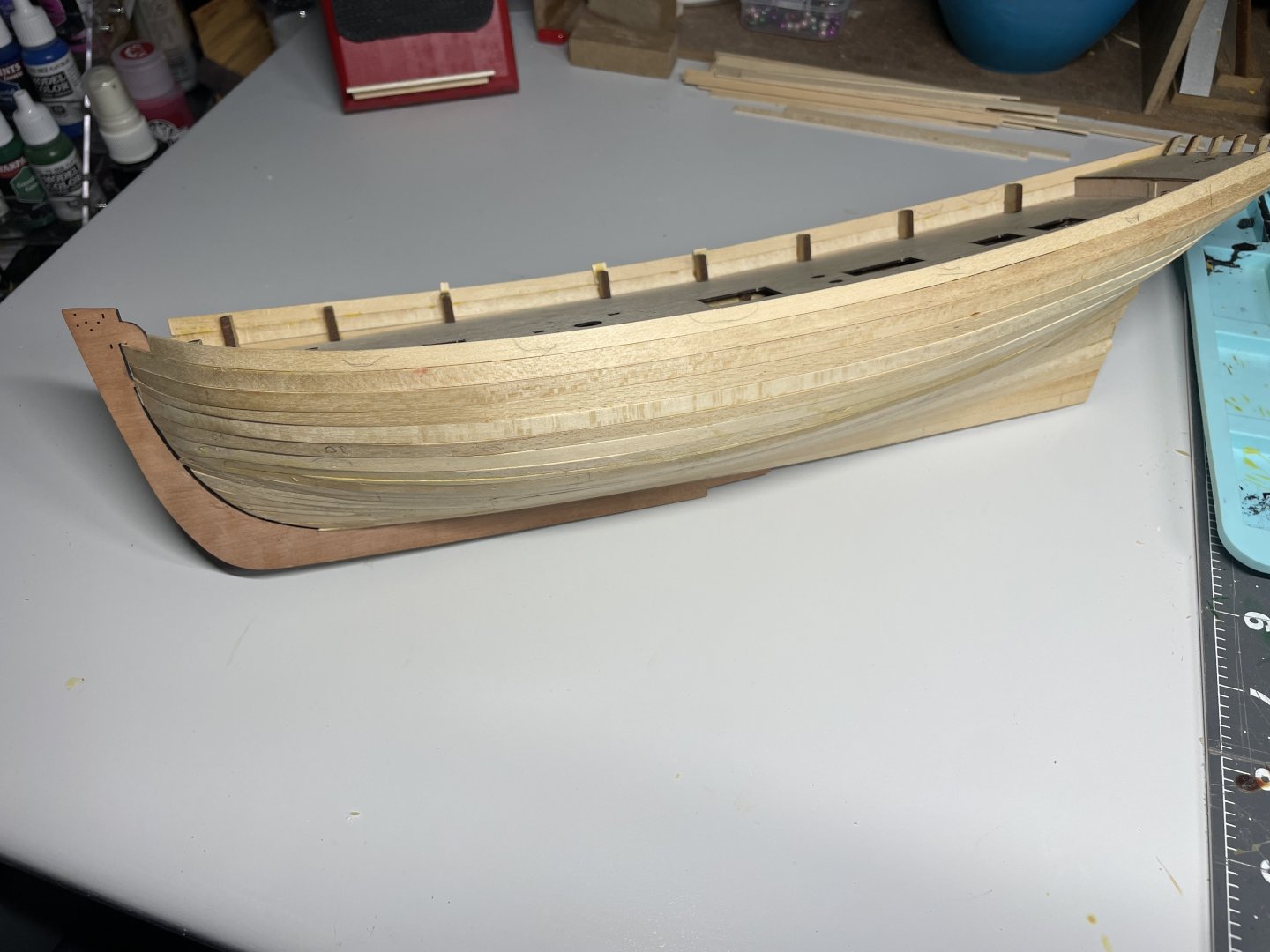
 This is my fourth build after completing the Dory, Pram and Lobster Smack. I’ve been looking forward to this build for a while. In real time I actually started the build on November 28th 2024. I’ve been worried about starting a log as it’s just one more thing to keep up on. Now that I have a head start I think it’s safe and I can keep it updated. Most of my build is based on build logs by @Thukydides and @Blue Ensign. I am very appreciative of the work they shared in their very detailed logs. There were many others also and I will call you out when I use a particular technique I learned. The beginning is pretty straightforward and has been covered very well before now so I will kind of speed through this part. The kit is very well made and went together very nicely. I did make up some little slotted blocks to hold her upright. There has been plenty of discussion about these parts not lining up on some build logs. I’ll be honest, they had me little concerned. Mine lined up fine. False deck going on. Now the fun really begins. Time to plank. I had decided early on that I was going to attempt this build at as high a level as possible. With that in mind and being new to planking a boat this size I had planned on the first planking to be a trial run for the second layer. I referred to many logs about planking both the Alert and others. I used @Chuck’s method of plank bending with water heat and a jig to make the lateral bends. I bought a little quilting iron with a tiny little foot. I saw someone on here use it. It is great. So here I go… ** One tip I will share regarding the little iron. I bought a timed outlet on amazon for about $12 and plug the iron into that. It has multiple settings for hours to be on. I usually set it for 2 hours, after that time it shuts off. So later I’m not wondering if I turned off the iron. I put a small piece of the pear planking in the rabbet to make sure I would have room to tuck that layer into the rabbet nice and cleanly. You can see I had to put a little skinny plank in there. By this point I’m just going by the seat of my pants. Best laid plans and all… I’m definitely going to need some filler, but overall I am quite happy with this layer. I couldn’t have done it without all the great logs and information about bending planks out there. That will about do for now. Next up, second layer planking! Chris
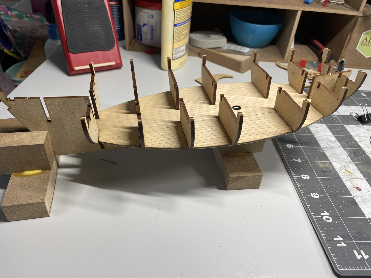


- 38 replies
-
- 9
-
-
- Alert
- Vanguard Models
- (and 1 more)
-
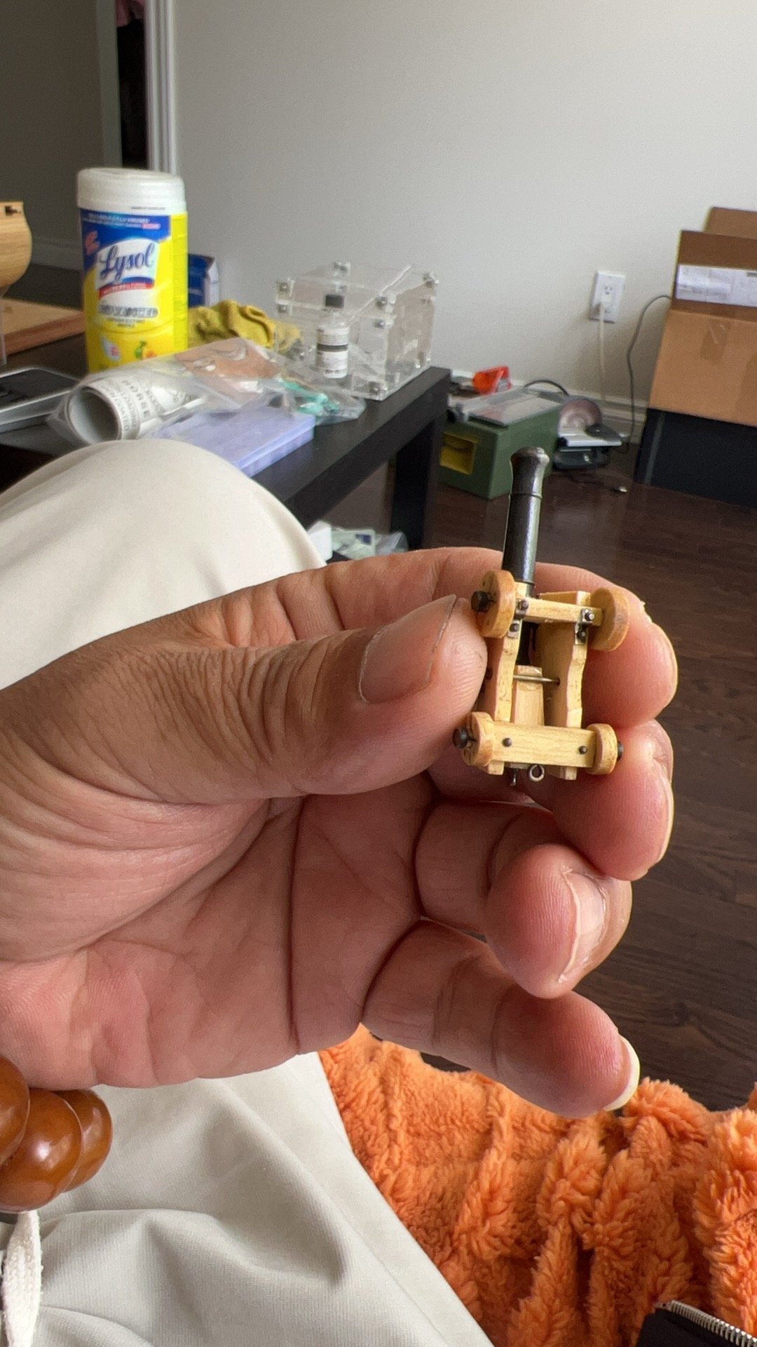
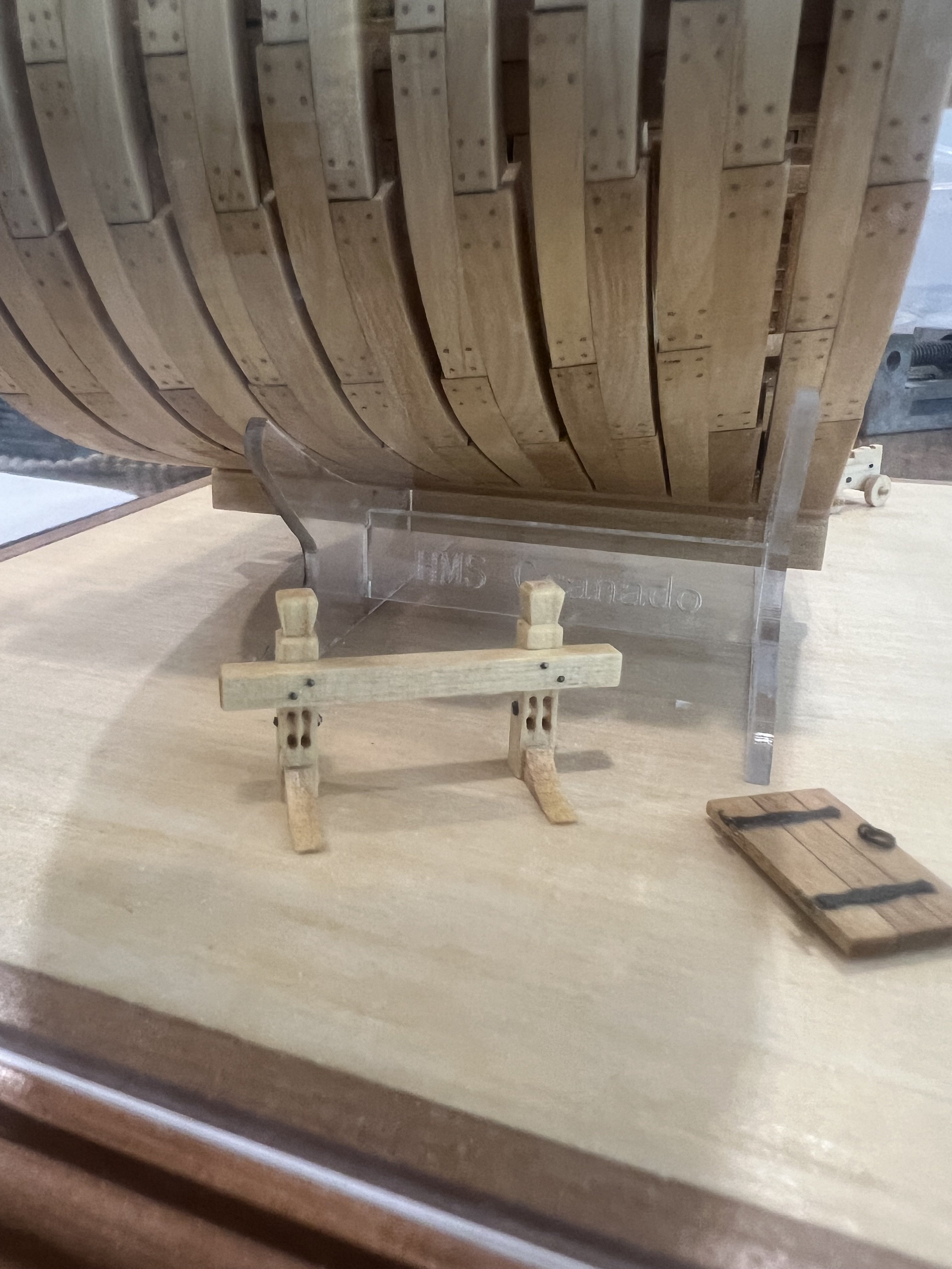
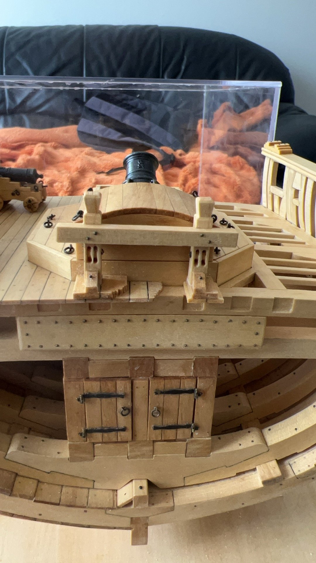
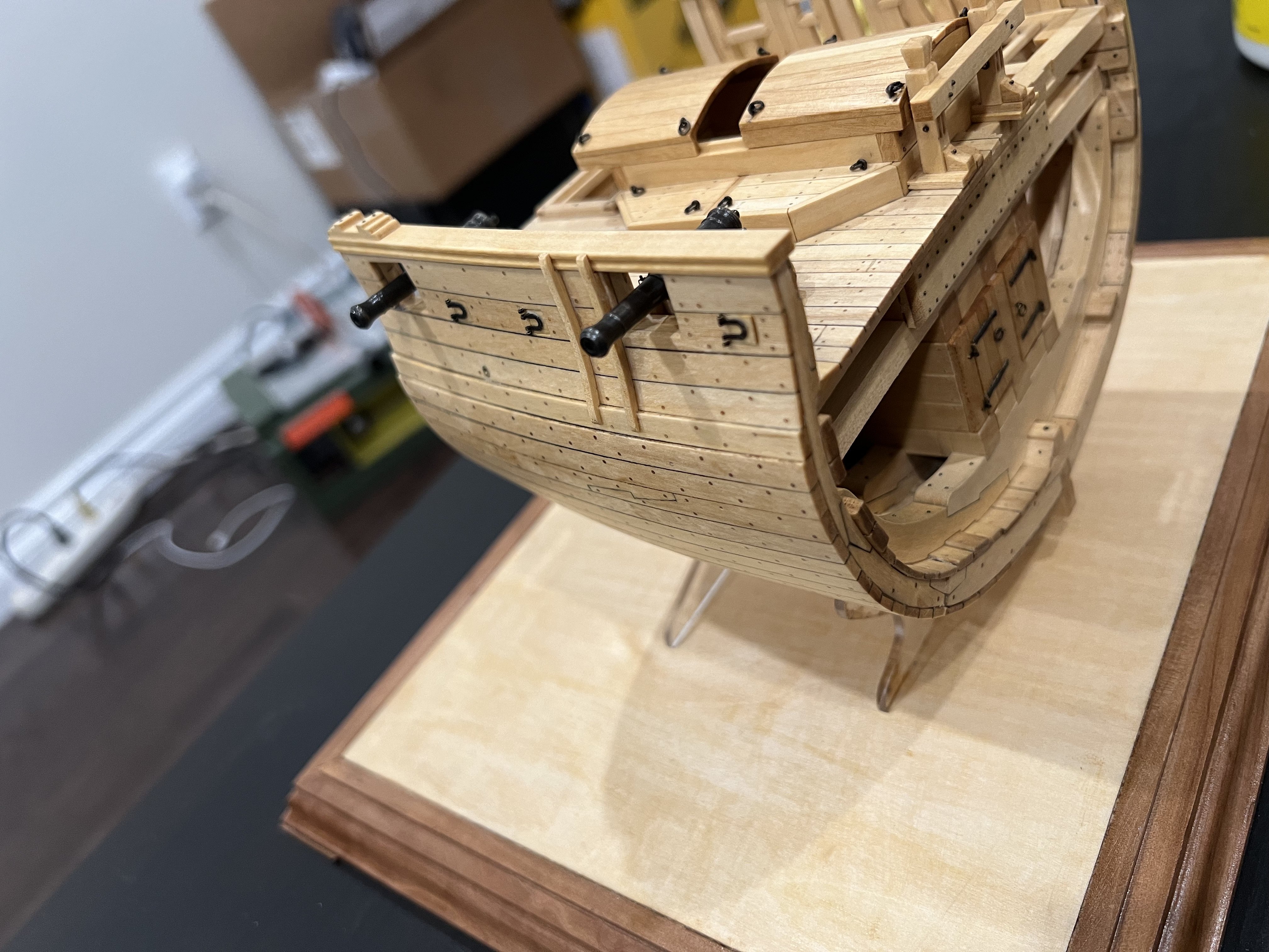
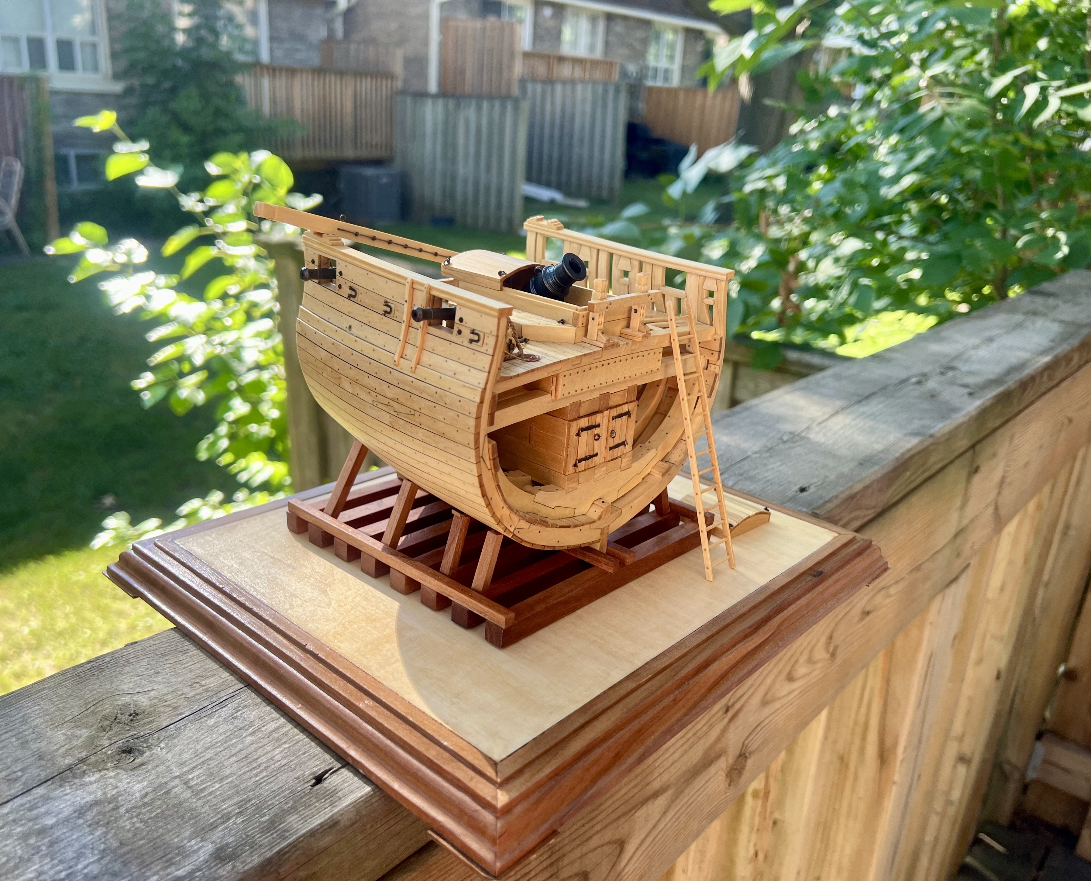
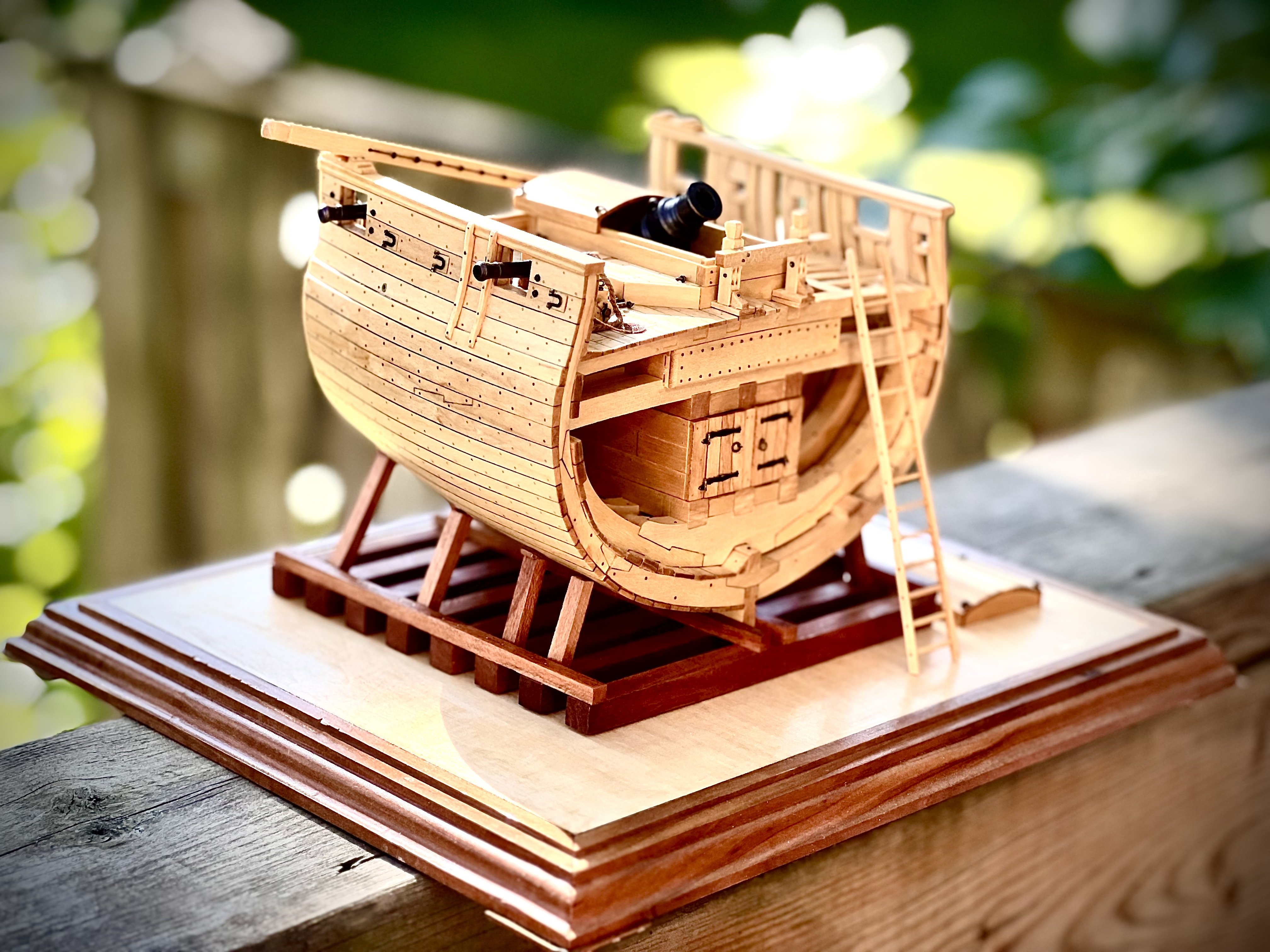
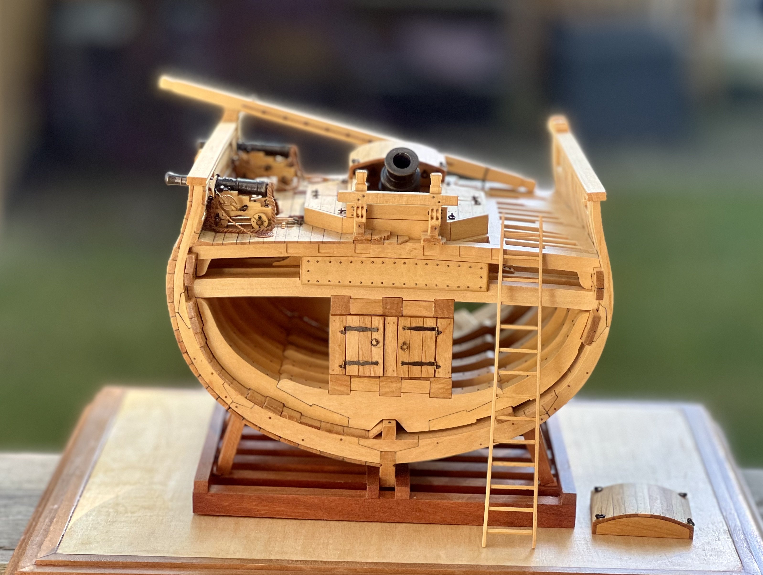
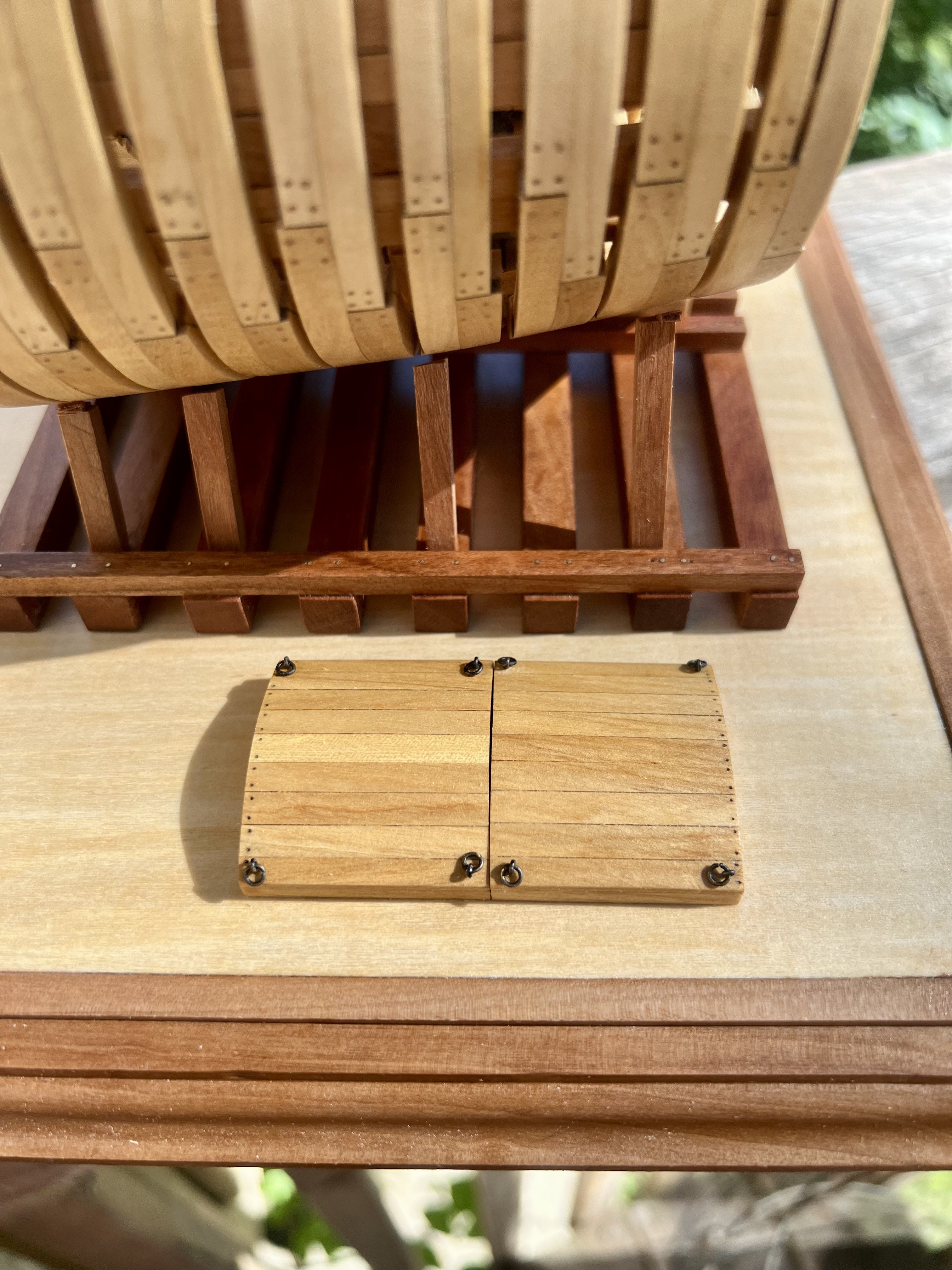
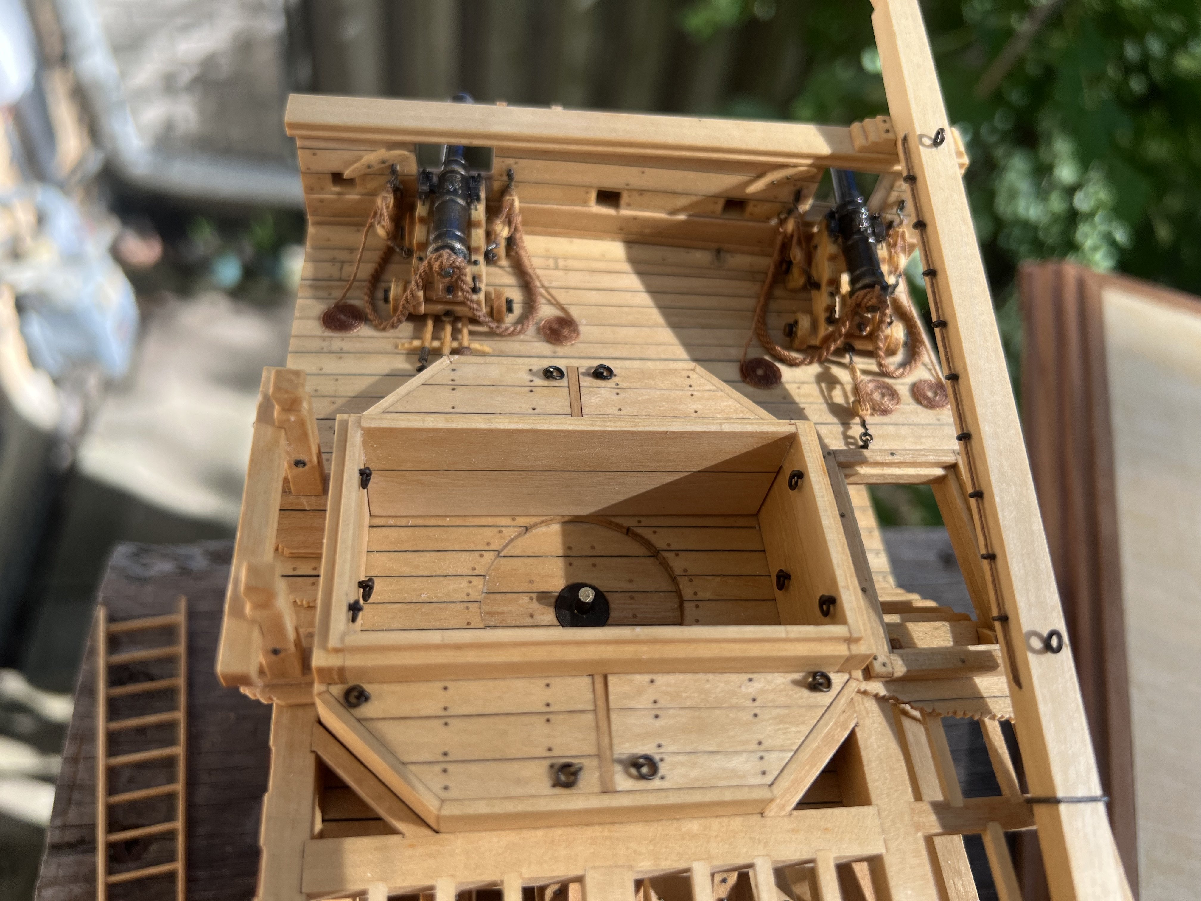
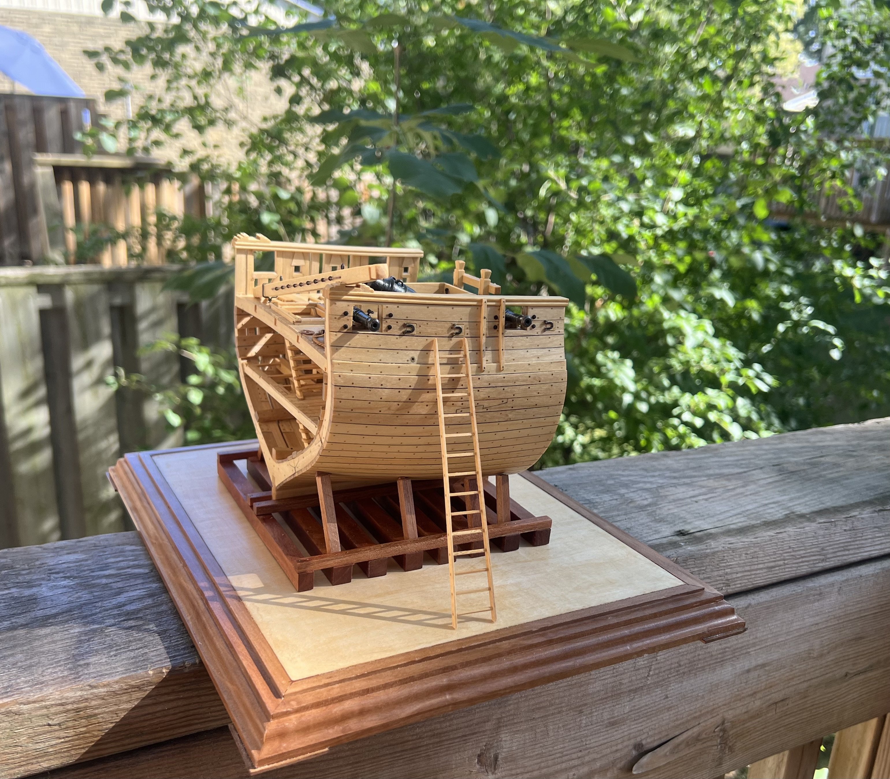
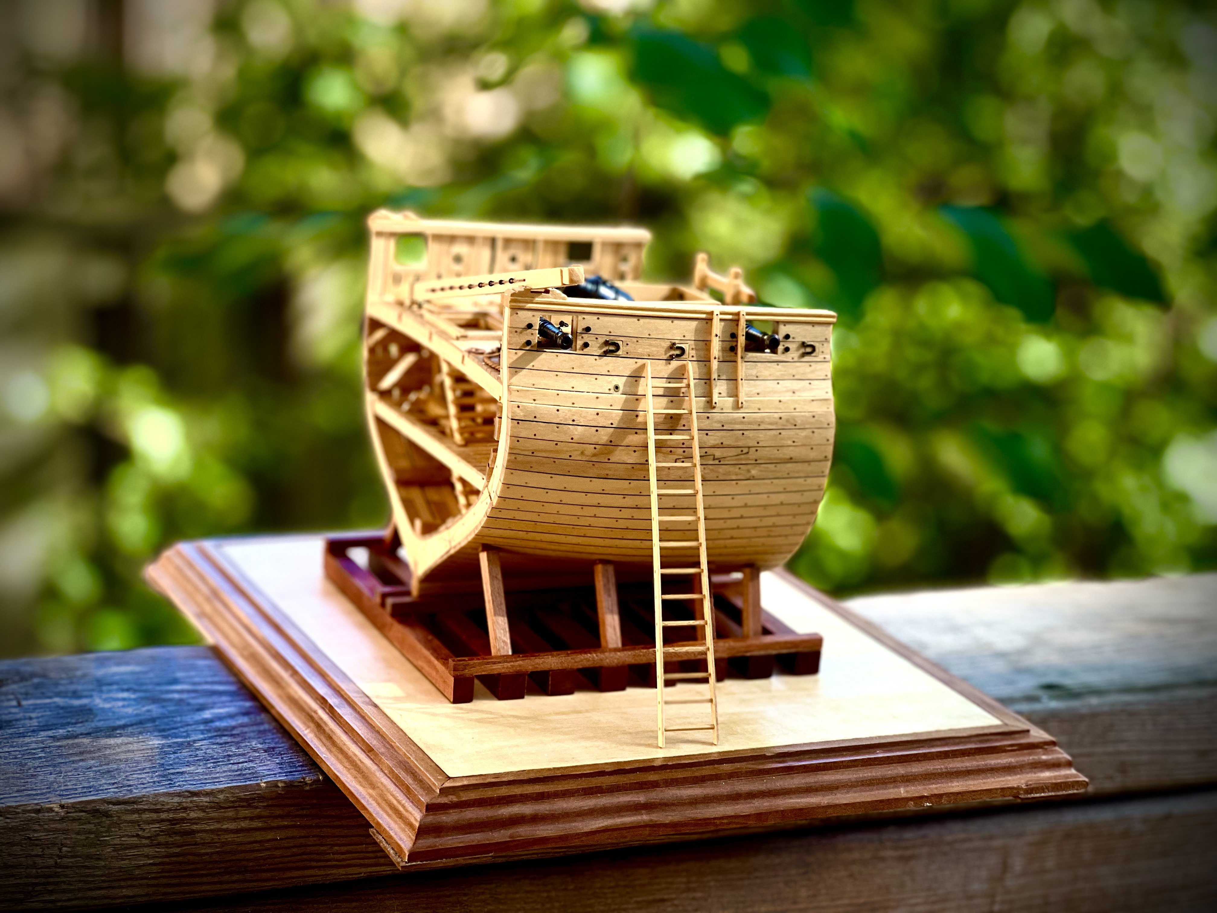
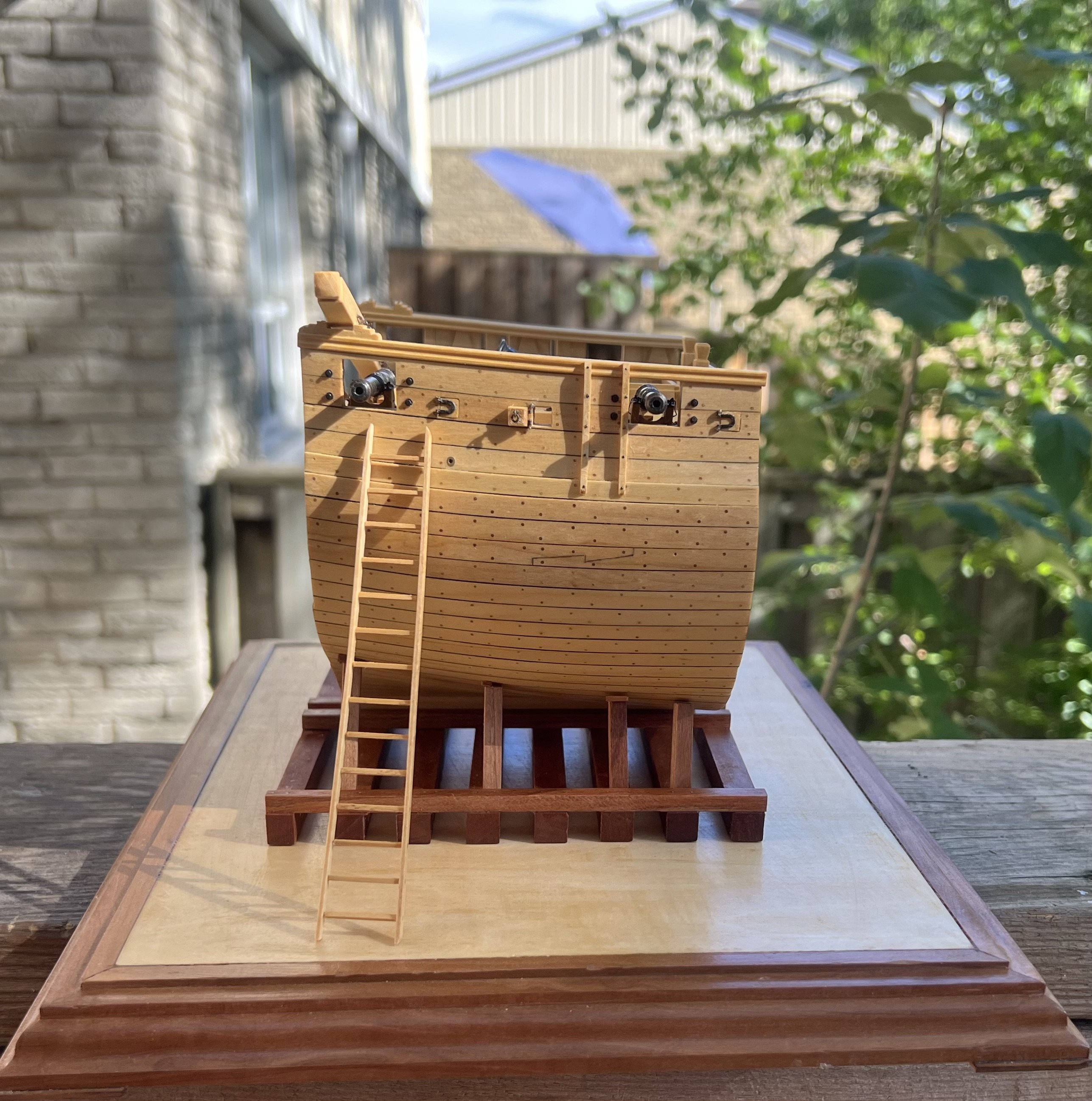
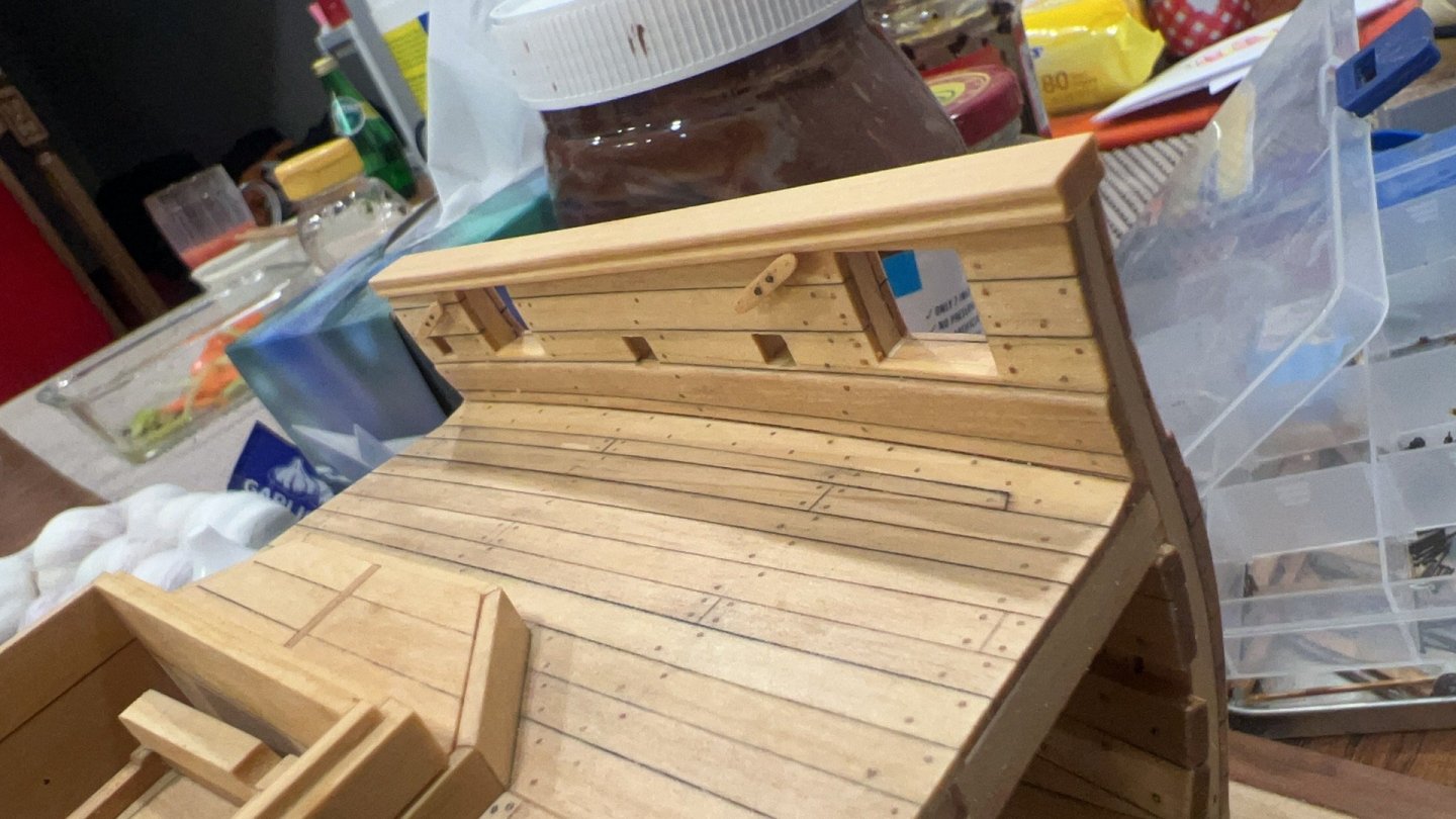
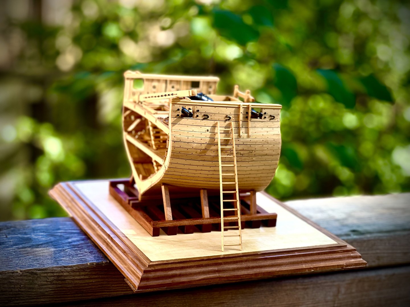
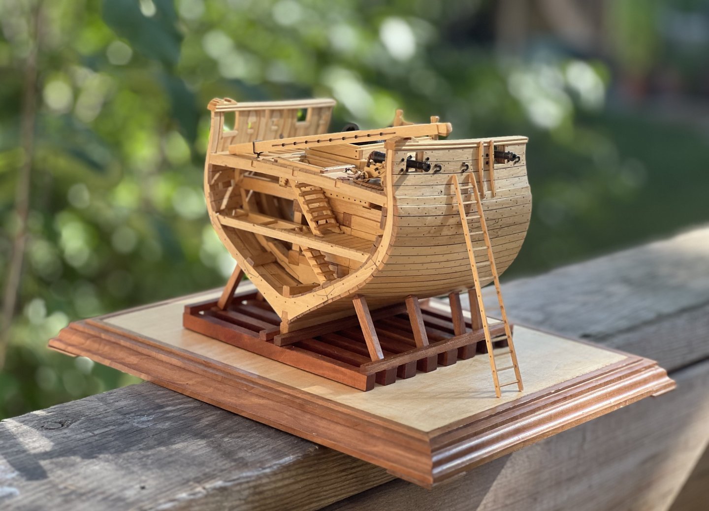
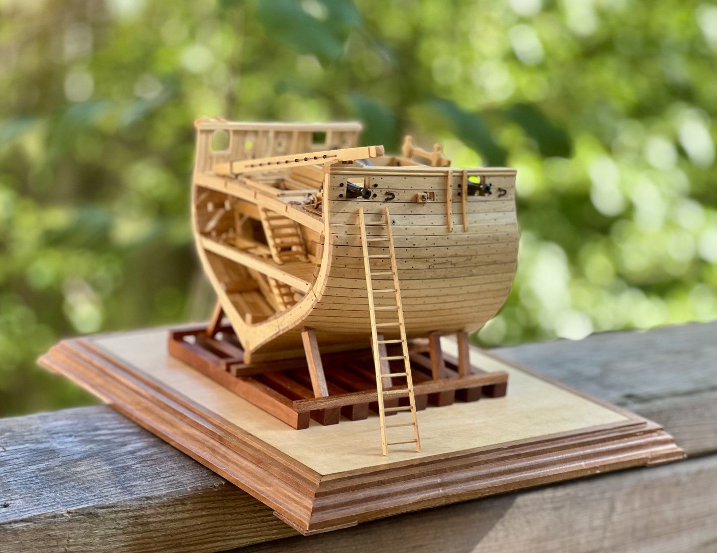
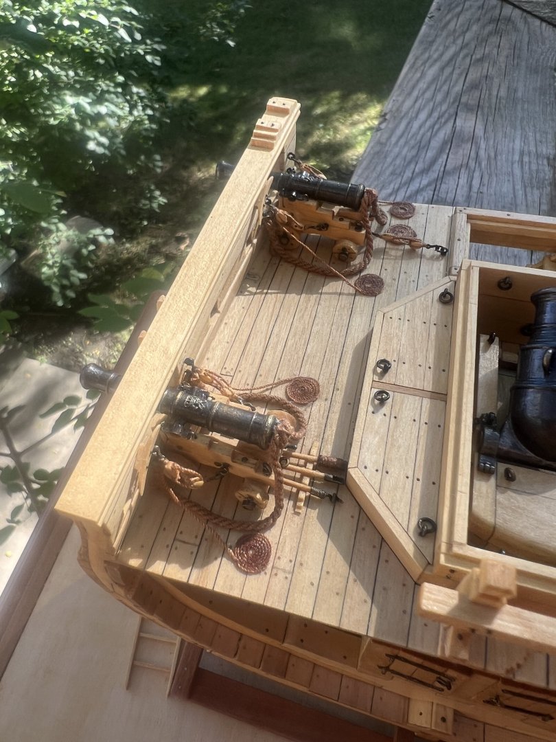
 Hi everyone, I'm a new modeler. I just finished HMS GRANADO (1742) - midship section - POF by CAF in 1:48. It's a very nice design, fascinating materials, complex keel, very fine brass castings.


-
 In the fall of 2019, I went to a model boat show in the Eastern Shore of Maryland, which ended up turning into a family mini vacation. At the show my wife decided to buy some raffle tickets and she ended up winning the Chesapeake Light Craft Annapolis Wherry kit. It's an interesting kit with a really nice 102-page spiral bound instruction manual (with three build photos per page). As an added bonus, CLC put out a 40 minute video on YouTube showing step by step construction. The model is built very similarly to their full sized wherry kit which CLC sells. Construction involves connecting the overlapping strakes with wire, which are then wrapped around the frames to form the shape (eventually, those wire ties are removed). For more information, you can go to CLC's website here: https://clcboats.com/shop/boats/scale-model-kits/annapolis-wherry-scale-model.html I should mention that @jbelwood and @gsdpic posted their very nice builds on here. Originally I wasn't going to post a build log, but I figured I might as well in case people are interested in seeing how this nice kit comes together.
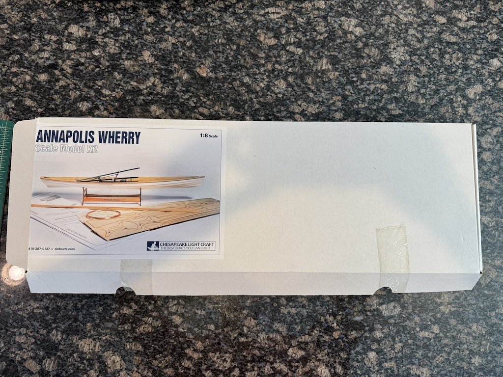
- 47 replies
-
- 11
-
-
- Annapolis Wherry
- Chesapeake Light Craft
- (and 1 more)
-
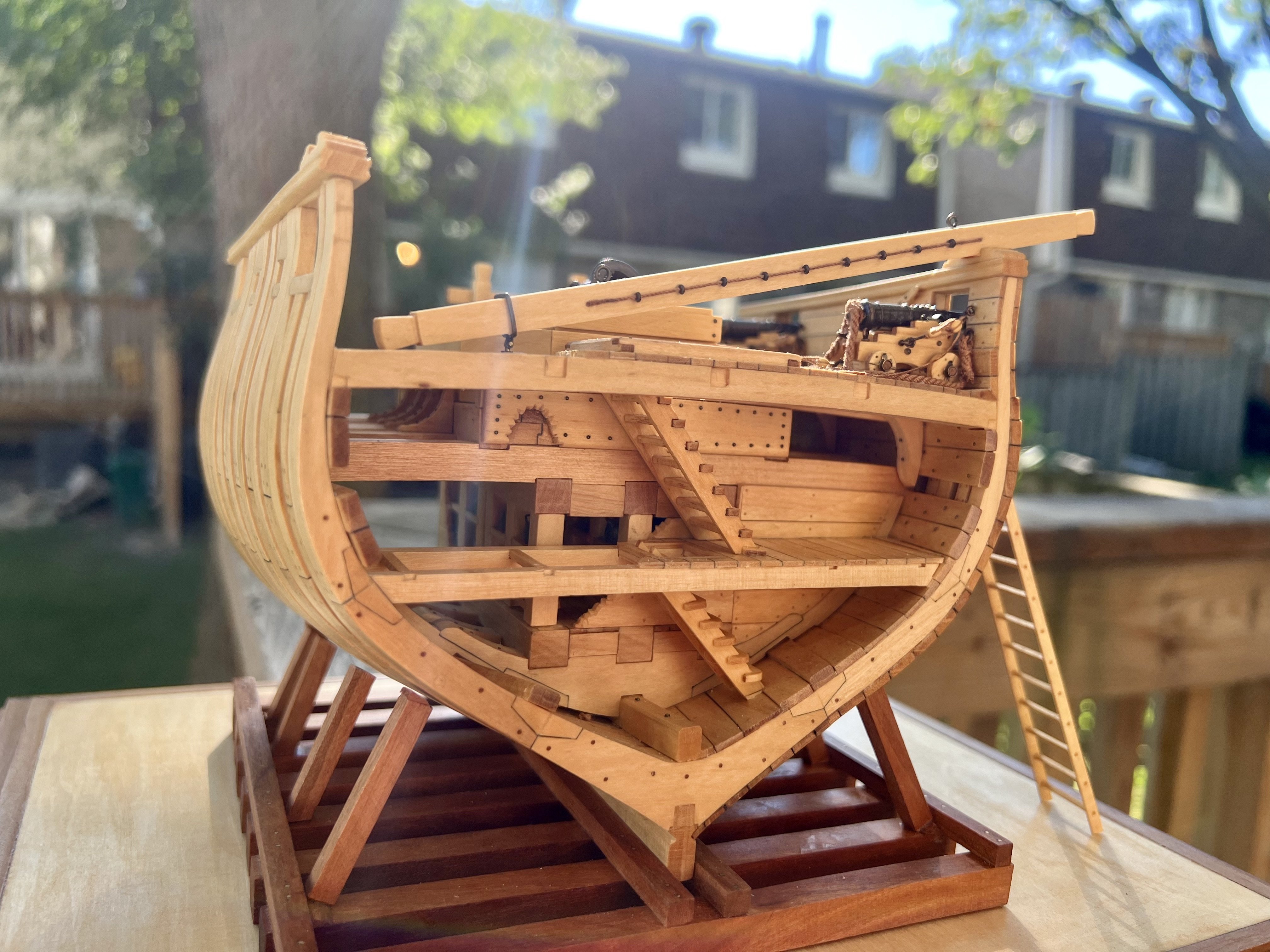
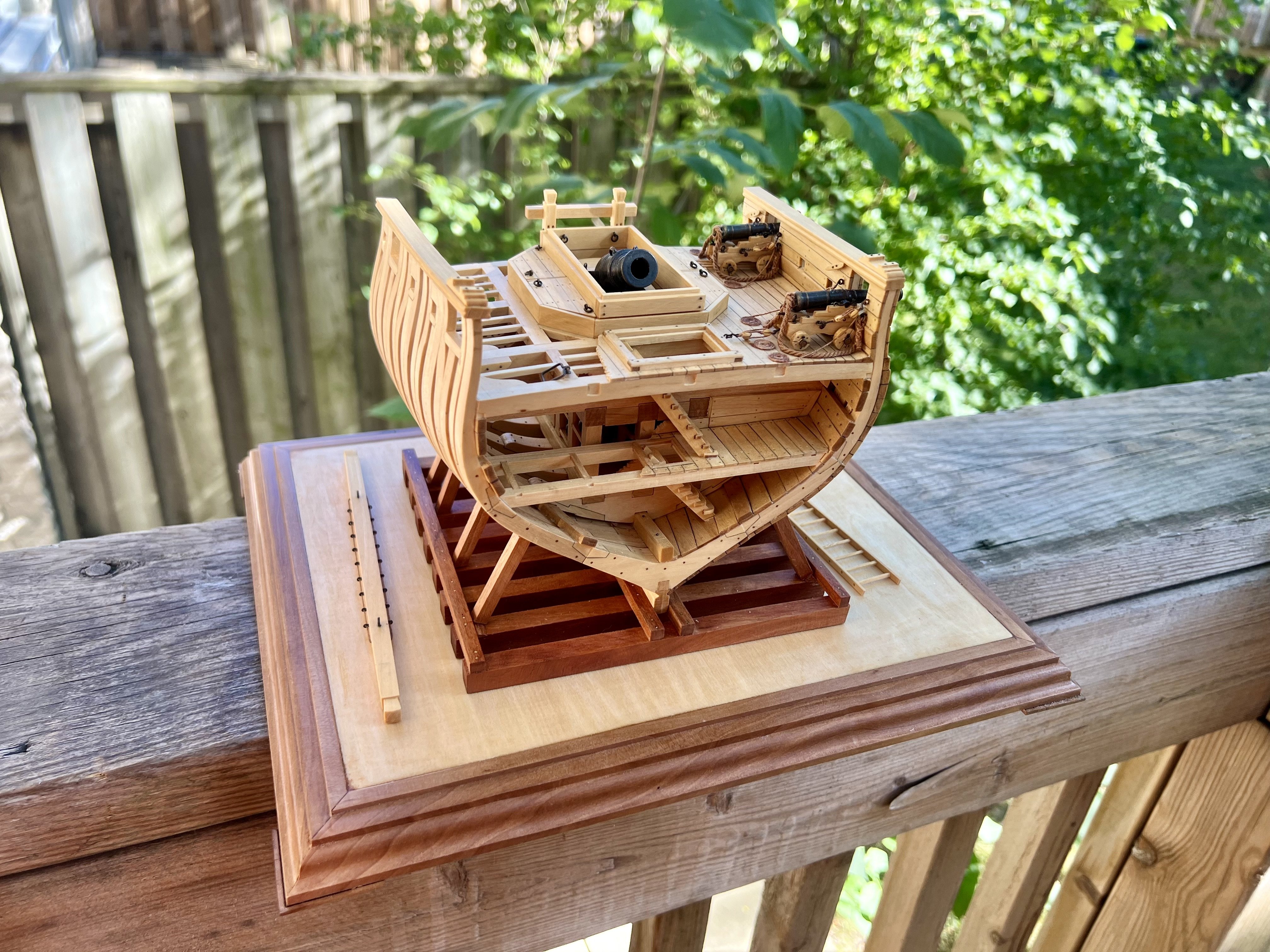
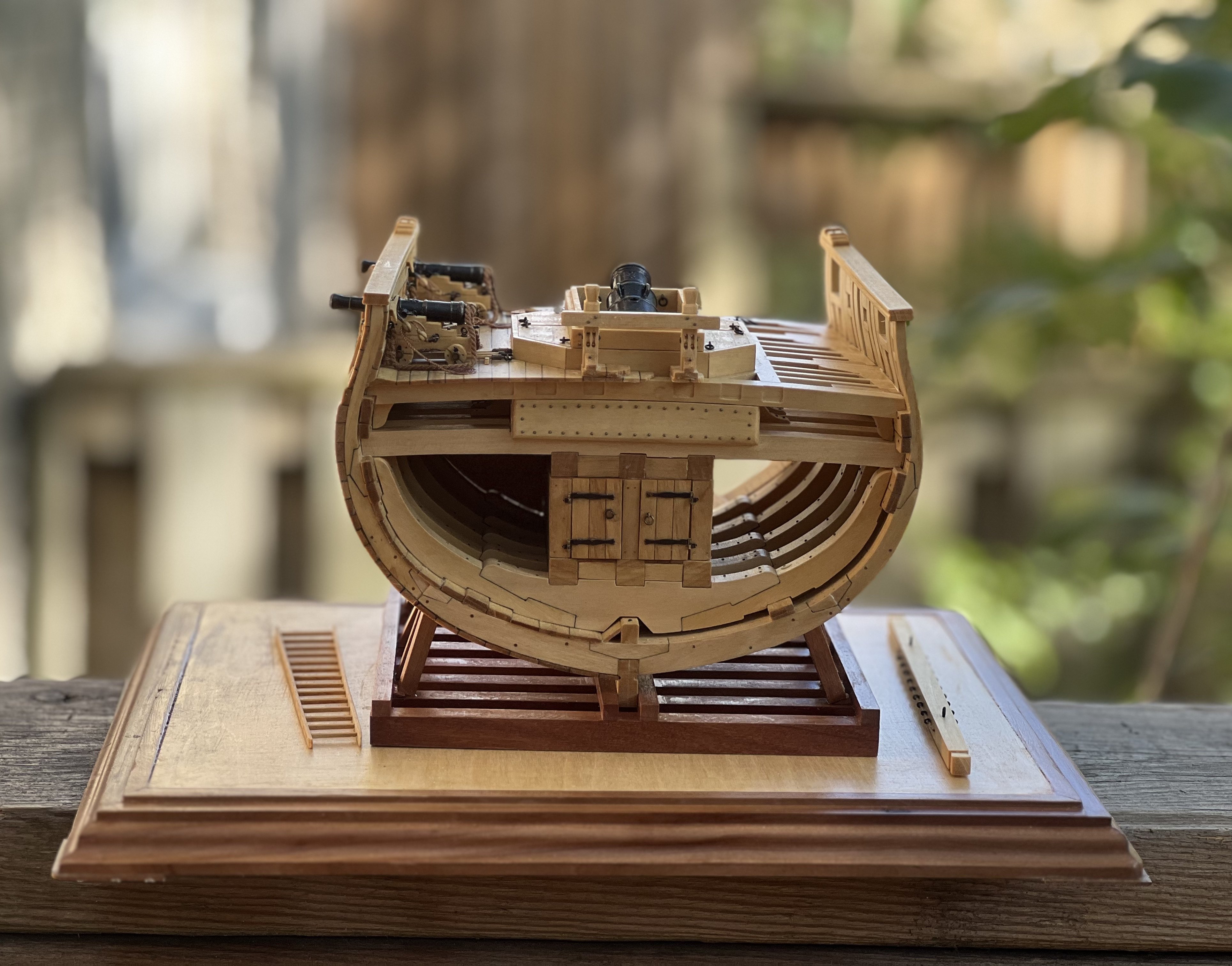
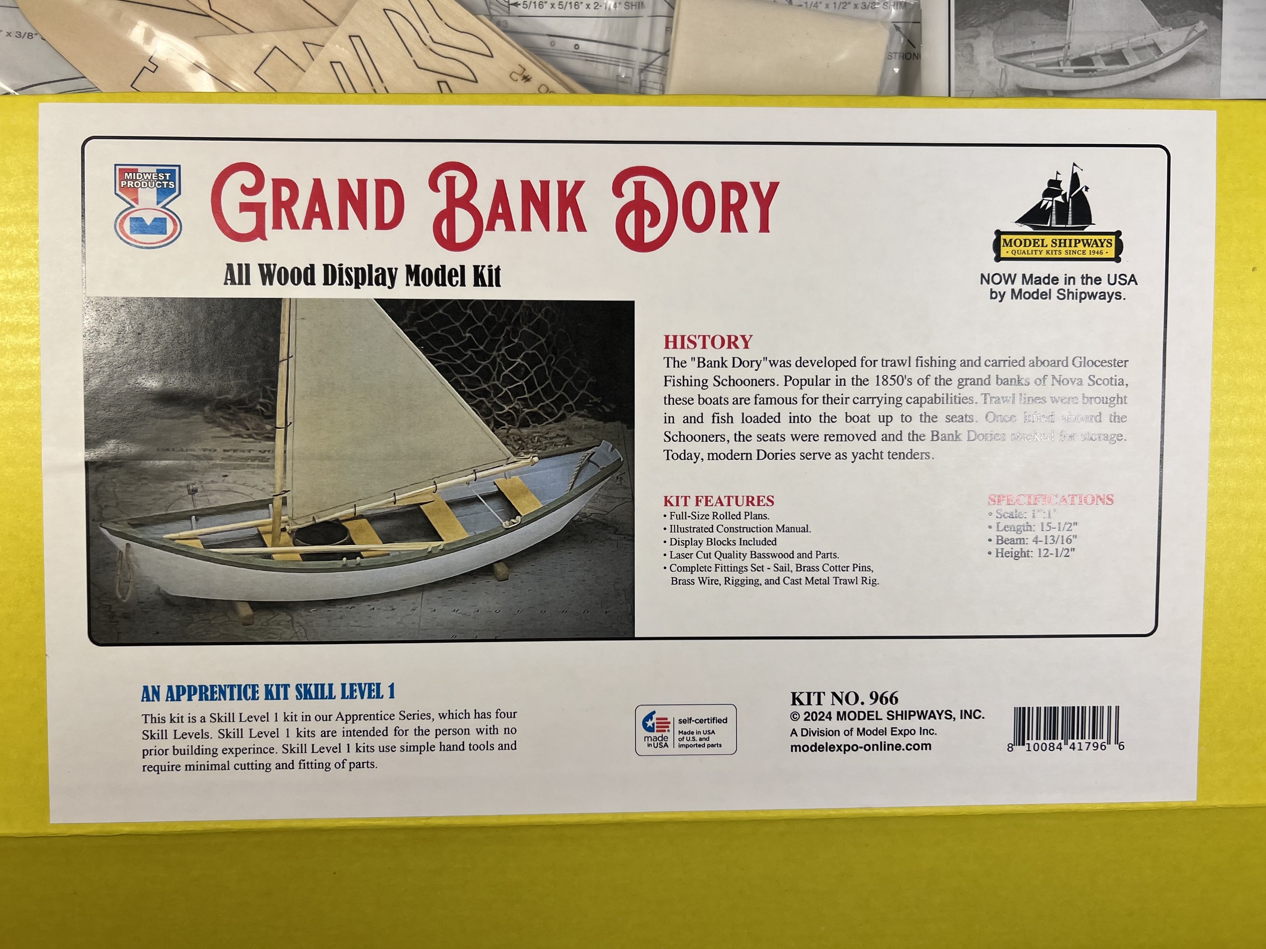
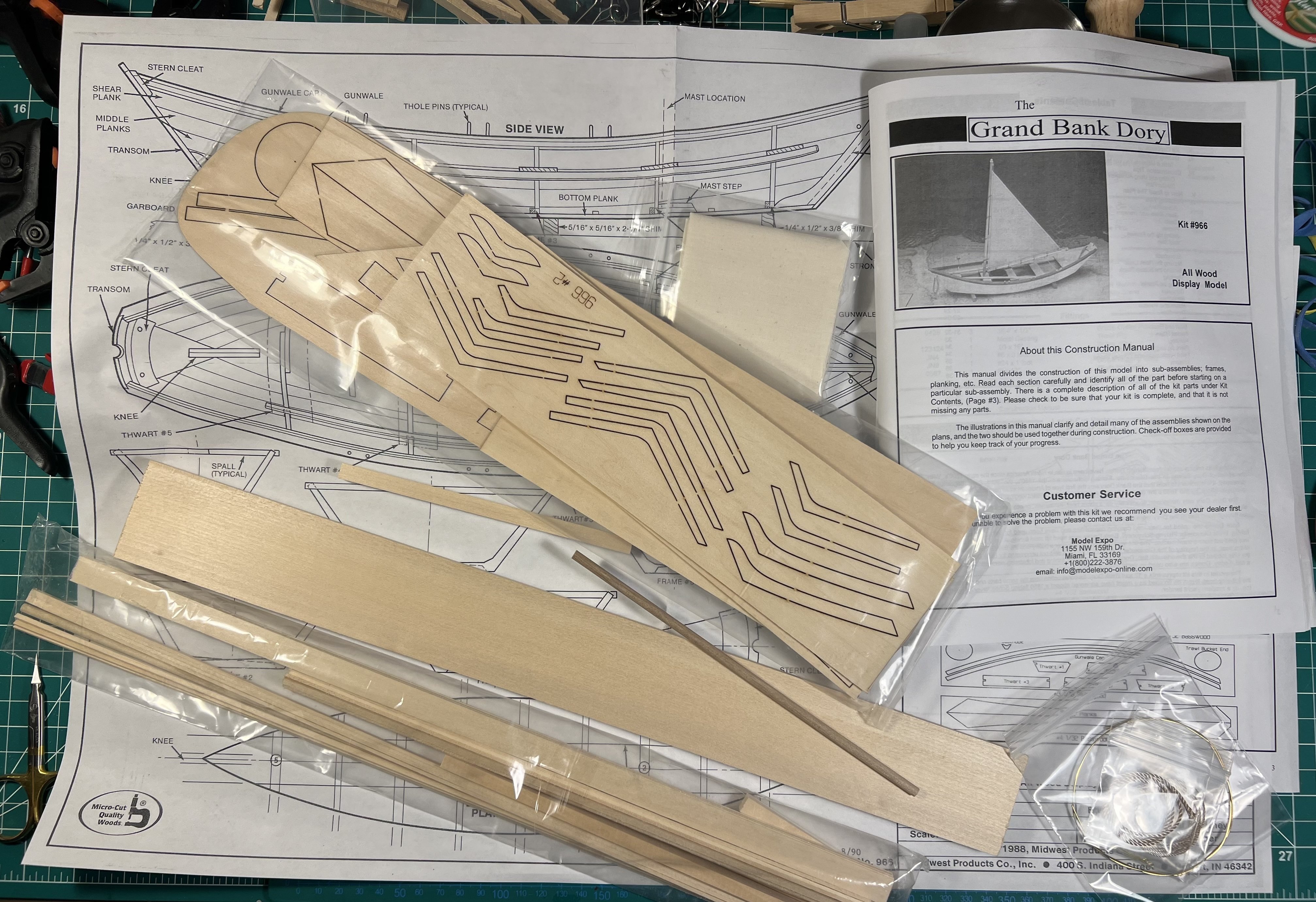
 I am starting to build another Dory, this one from Midwest Products (a division of Model Shipways / Model Expo). I think I read that Model Shipways / Model Expo bought the designs for the Midwest Products kits and have been reissuing them with better materials. I think I also read somewhere that the old Midwest Products kits might have used balsa wood - this one uses basswood - but I don't know how long ago that was. I'm planking my Ranger slowly and researching and reading how to rig my Sherbourne. I didn't want to start another complicated kit and remembered that I had bought this kit in my buying frenzy during a Model Expo sale in the fall. It will be interesting to see how this build differs from the other Dory I build. Unlike the other Dory, this one is larger scale (1:12 instead of 1:24) and has a sail. These easy kits can be completed quickly and let me try out different approaches that I likely will be able to use on more complicated kits, and maybe be able to make progress more quickly on those than I might if I had just plunged into larger complicated kits more quickly. Like some other builds, I'm putting some notes here about this kit for future builders: - Like the Model Shipways Dory (and other Model Shipways kits) the written instructions don't always match the supplied materials. I imagine that the instructions were written years ago and that over the years the suppliers have changed and the methods used to cut the wood have changed. Unfortunately, the instructions are rarely updated to reflect those changes. So it's easy to be confused and to make a mistake. - Unlike the Model Shipways kits (or the Vanguard kits), in this Midwest kit, there are neither written (laser etched) labels or numbers on the sheet identifying the parts. The only way to know what part is what (and lots of parts are pretty similar, especially the frame pieces and the stem), you need to rely on the instructions. Well, when the instructions don't match the parts, you have a problem. - Before I realized the disconnect between the instructions and the materials, I was adding the stem (made from two pieces glued together) and was following the instructions that indicated that the stem piece was next to the transom on the sheet. Well, later when I was starting to work on the frame pieces, I realized that the instructions didn't match the sheets and I had inadvertently used frame pieces as the stem pieces. The stem was on the opposite corner of the sheet from the transom, contrary to the written instructions. - I did then discover that the sheet in the box that listed the pieces in the kit also at the bottom had a map to the parts on the sheets. If I had discovered that earlier (and had paid closer attention) I made not have made that error. - Also, be careful around sharp blades. After I made my error and had to loosen the glue using some alcohol, I was using a flat-bladed hobby knife to loosen the part some more and the knife slipped and went into my hand. Thankfully I was able to avoid a trip to the emergency room. - It is interesting how two kits (Model Shipways and Midwest) of the same boat (albeit at different scales) can be constructed so differently in many ways. Doing both gives you a sense of the degrees of freedom that come with kit designs and how things can go together.
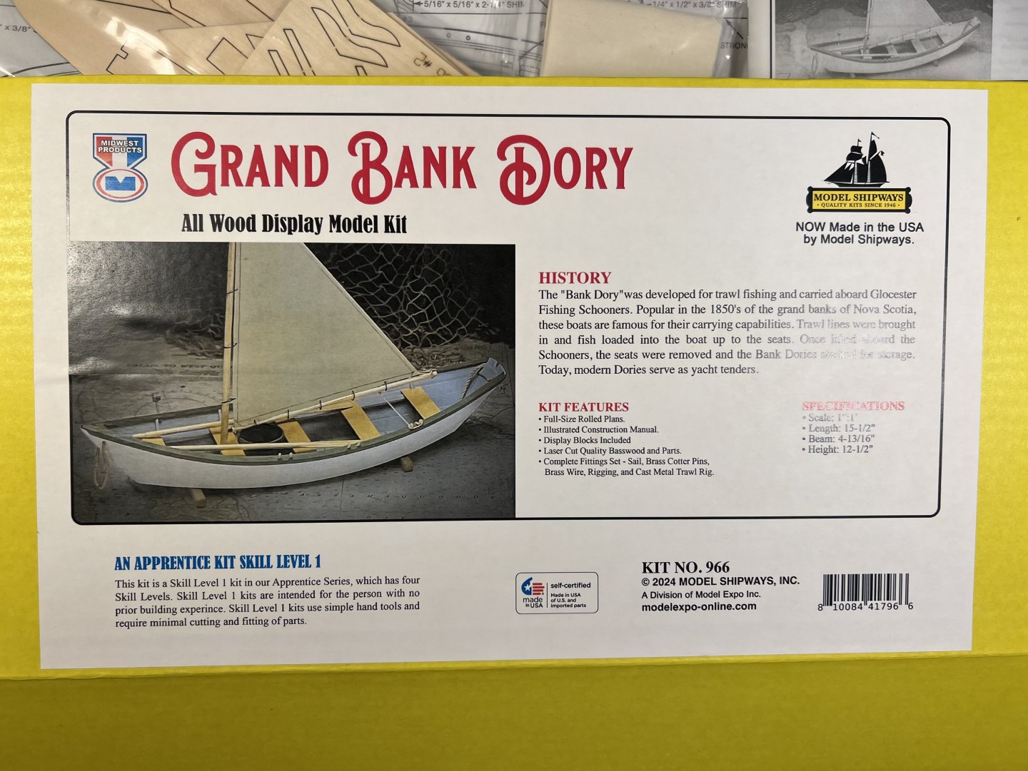

- 71 replies
-
- 2
-
-
- grand banks dory
- midwest products
- (and 2 more)
-
 I picked the East Coast Oyster Sharpie for my next project using the plans and practicum by Bill Strachan and available from the NRG. Everything is outlined at https://thenrg.org/genericsharpie.php, and the practicum has tons of pictures. It is so well illustrated that I will probably limit the build log a little and not include things that are well outlined in the practicum, which is available on the NRG website for free. The plans are beautiful, the build looks like it won’t take 6 years like my last one did, and it looks like a very different kind of project, which will make a good break. I’m a little nervous as there are only two logs on MSW, and they both stop fairly early in the build. I started back in February with big plans to keep the project moving along, then COVID-19 hit. I work in health care, so rather than extra time to model at a social distance, work has been completely consuming in terms of patient care and pandemic preparation and management. I mostly go to the workshop at the end of a long day to decompress. Working while tired has led to a lot of re-do’s already. Not sure if late 19th century Sharpie’s had names, but this one will be christened “Corona”. So far, I’ve made the two building jigs. There have been a few discrepancies between the plans and practicum, and I’m starting to work off the plans with the instructions more as a guide. Jig 2 went together easily. The first jig needed some shims on frames 5 and 6. Not sure what happened as I cut to the line in terms of frame shape. I had a nice smooth curve along the top, but needed to shim the sides of frame 5 and 6 around 1/64 and 3/64 retrospectively. With the shims, I have a smooth curve along the sides as well. There are also some slight discrepancies between the as built jig and the profile on the plan, but given that everything seems fair, I don’t expect it will cause a problem later. From this point on, I’ll be building the model instead of jigs, so will include more pictures. I have enough boxwood left over from the cross section, so plan to use it. I usually use contrasting wood colors, but have wanted to try a model using a single type of wood. I will finish in wipe on poly. I think the rigging and metal work should have enough contrast to keep it visually interesting.
- 75 replies
-
- 12
-
-
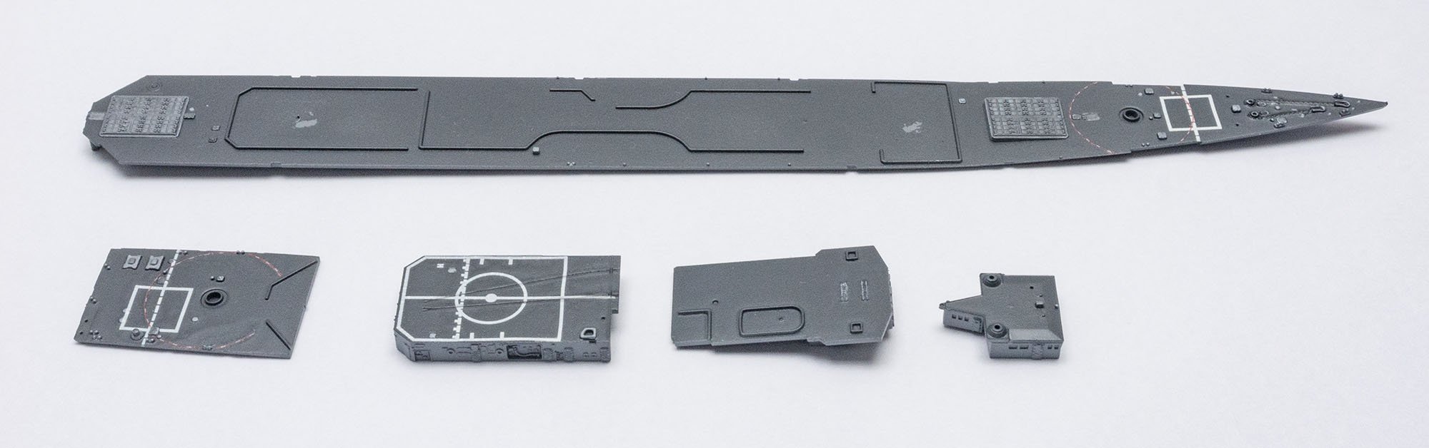
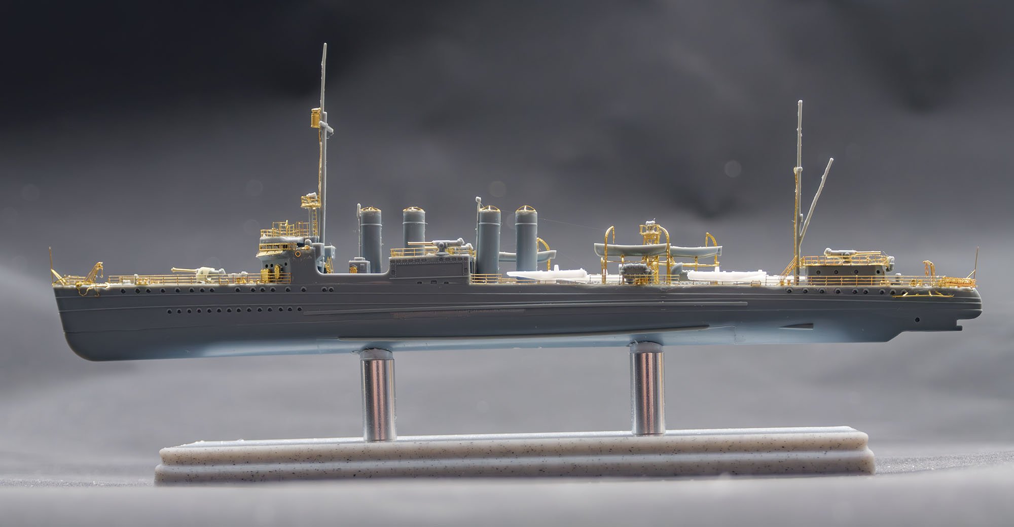
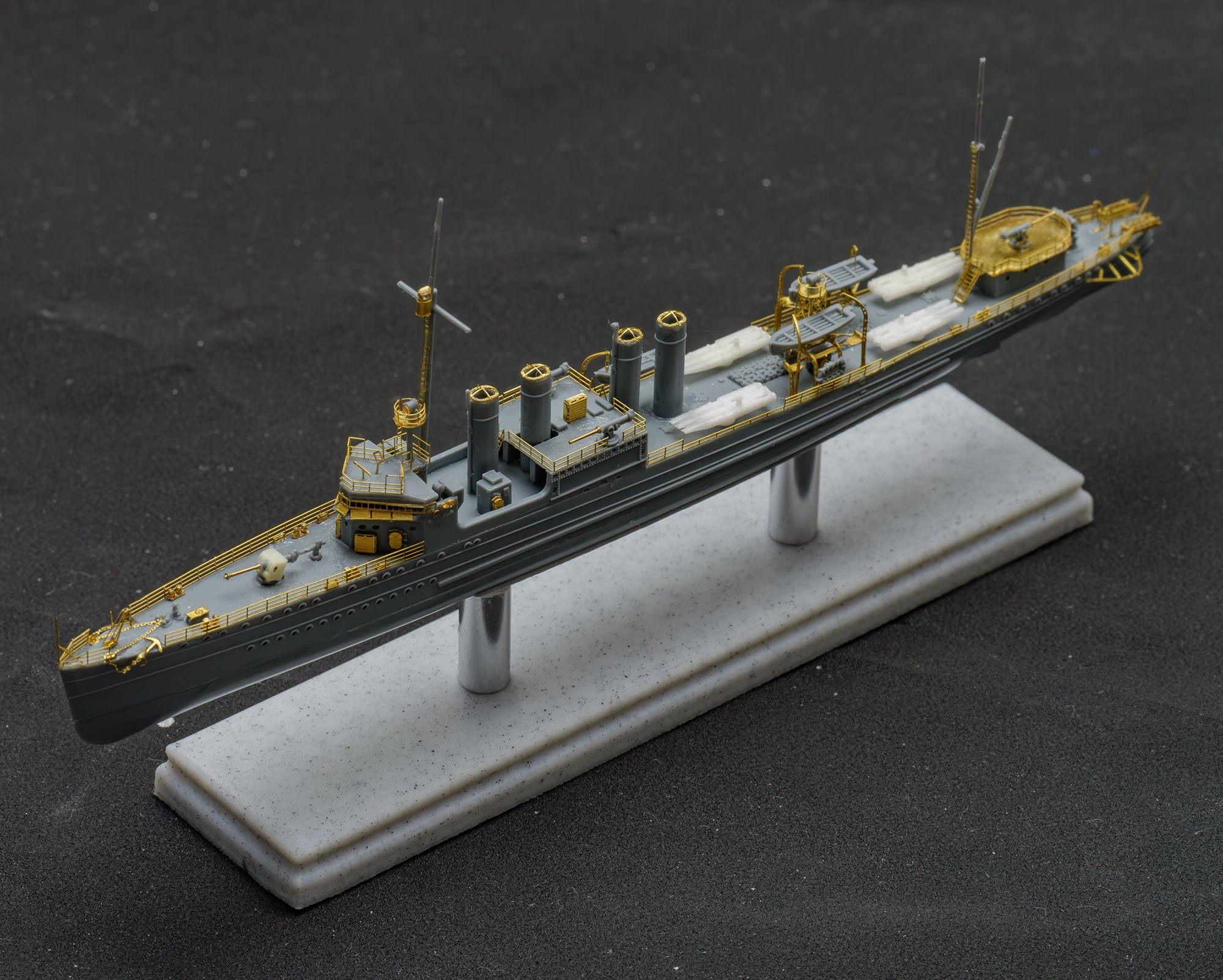
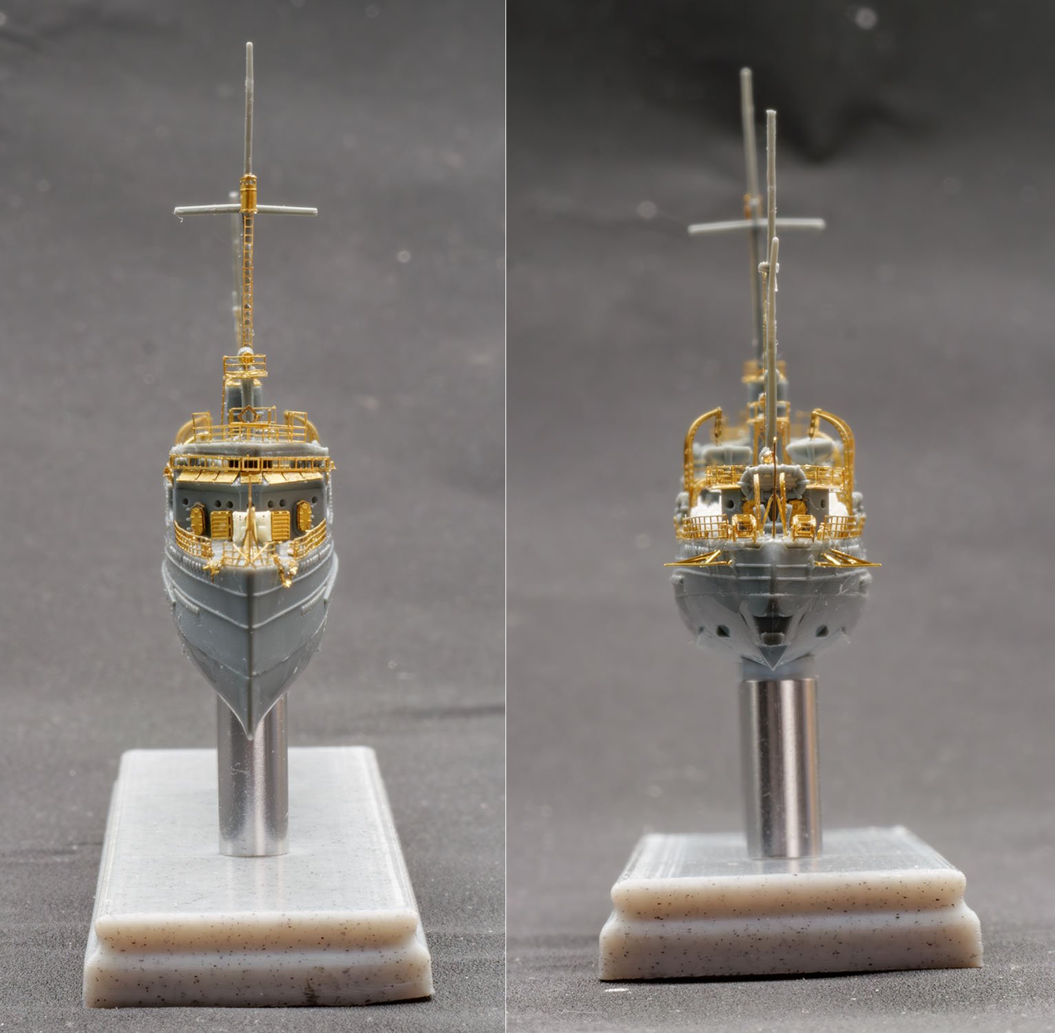
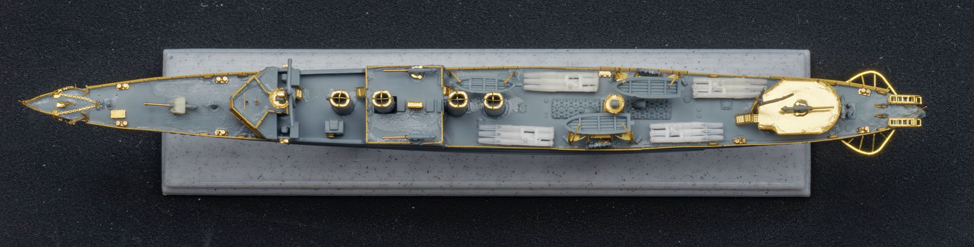
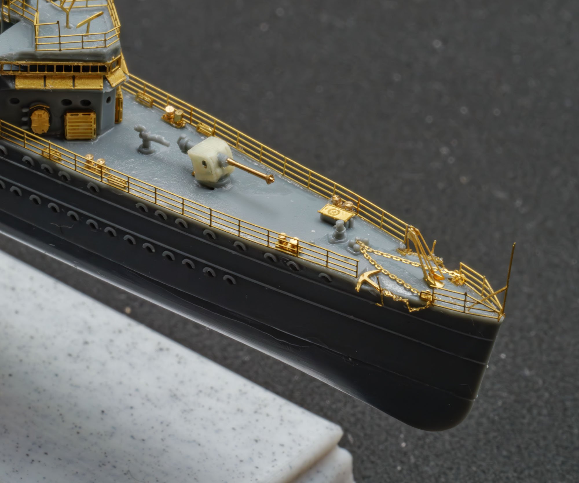
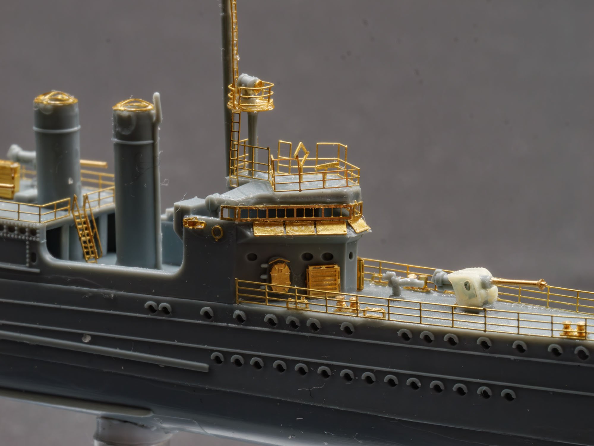
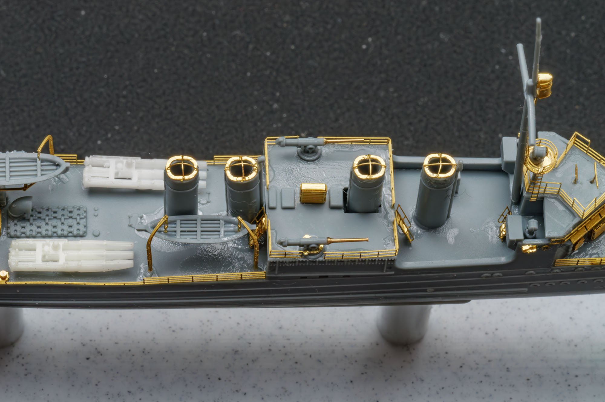
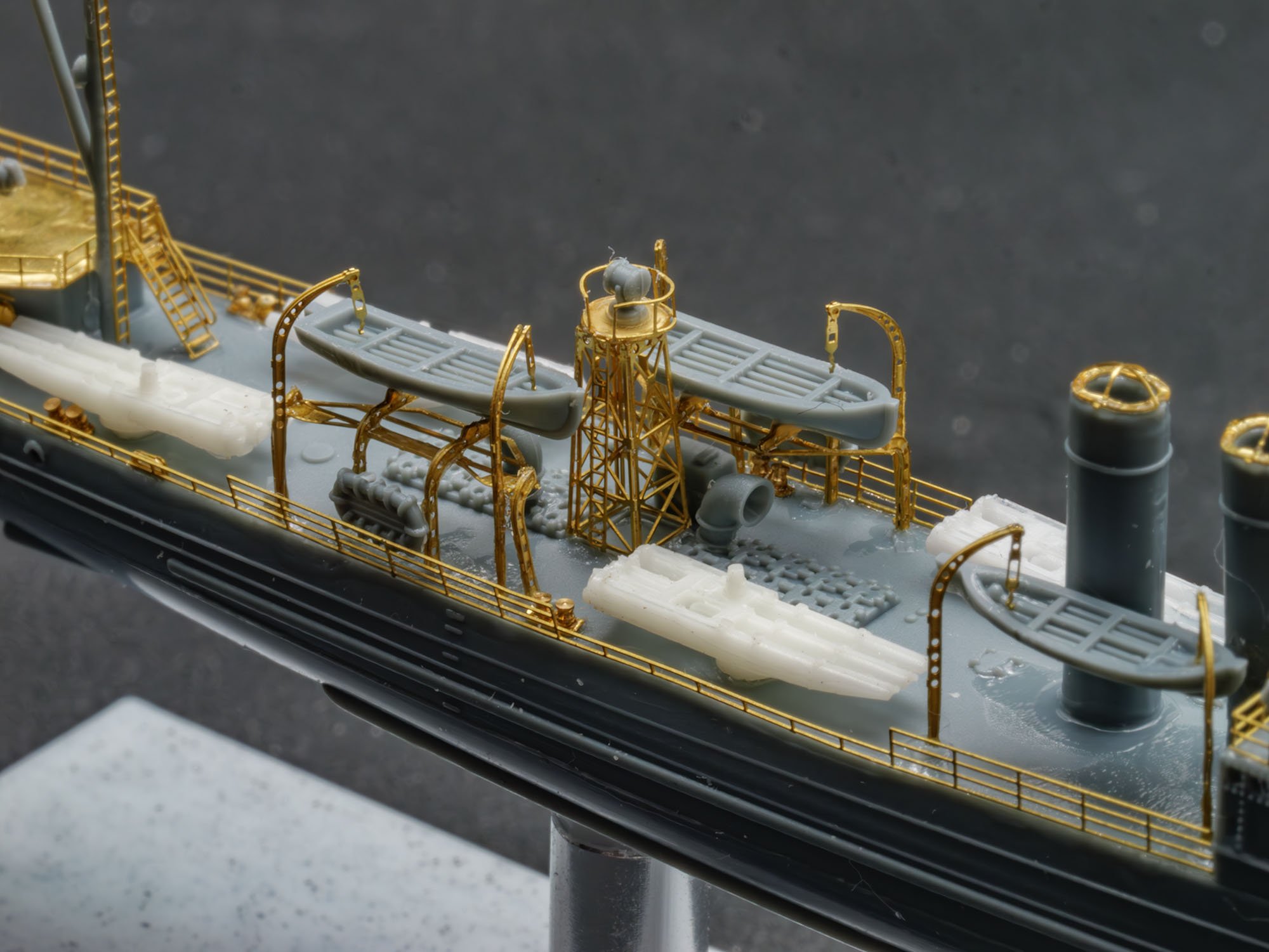
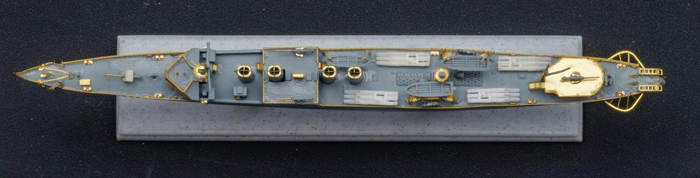
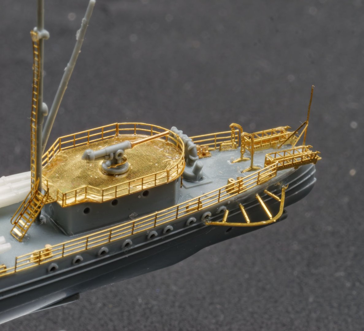
This is an USS Ward DD-139 1941 kit from Flyhawk. I tested some new ideas. I've completed assembly before I paint it.


-
 I am resuming a build of the Mantua Albatros "Goleta tipica di Baltimora" - a Baltimore clipper, fitted out as a revenue cutter. I started the kit back in the mid 1980s and finished planking the hull. Then other things came along (buying a house, getting married, etc.) that left little time for ship modeling. The partially completed hull has resided on my bookshelf for about 30 years. I really like the lines of these ships so I decided to resume the build, but I am not sure what it will end up being. I am building it to get experience with a few new techniques. NOTE: THE RESULTING MODEL DOES NOT REPRESENT ANY ACTUAL SHIP. I MADE SEVERAL ERRORS IN THE CONSTRUCTION, AND HAVE TRIED TO POINT THESE OUT AS I GO ALONG. BUT I HAVE PUT A LOT OF RESEARCH INTO TOPSAIL SCHOONERS AND REVENUE CUTTERS SO I HOPE THIS THREAD WILL BE USEFUL TO OTHERS. This is the 1980s kit, and it is different from the latest Mantua Albatros kit description on line. The new kit has a false deck, apparently of thin plywood, and the 1980s kit does not. The newer kit seems to have mahogany hull planking, and the older kit used tiglio or lime wood. The older kit came with two drawing sheets, hull construction and sail plan, plus brief instructions. The Mantua web site says the new kit has three drawings, and at least one appears to be the same as the 1980s kit. The 1980s "instructions" are a joke - one page saying to assemble the hull frames, plank the hull, assemble the base, build the masts and finish the rigging - just about that brief! For me this isn't a problem. I have been researching and scratch building plank on bulkhead models since I was a kid. I have searched and found no record of a Baltimore clipper named "Albatros." The kit name suggests Mantua's "famous" ship is just "typical" of a Baltimore clipper. Looking at the plans for the model and plans for actual Baltimore clippers I can see quite a few differences. This raises several questions, and I would appreciate any help you can offer. 1. Scale. The 1980s kit plans and instructions give no scale. Comparing with other ships I guessed it was about 1:64 scale. Some sites say the Mantua model is 1:55 scale, and the latest Mantua web site says it is 1:40 scale. The model is about 27" long (tip of bowsprit to end of the spanker boom), and this is what Mantua says is the length of their latest Albatros model. The waterline (length between perpendiculars) is about 17 inches. This would give a full scale hull length between perpendiculars of: 1:40 - 56' 4" and about 70 tons 1:55 - 78' and about 100 tons 1:64 - 90' 8" and about 180 tons Baltimore clippers were constructed in approximately all of these sizes between 1800 and 1820. Since the model has only six cannons plus one larger gun on the centerline, I assume the 1:40 scale is close. There were several 60 foot ships built. Any thoughts? 2. Mast angles. The Mantua plans show the rake of the fore mast to be 2-3 degrees and the main mast to be 5 degrees relative to the water line. I examined plans and drawings for 17 Baltimore clippers and found the mast rakes to be: Fore mast - 11.5 degrees average, with a range of 7-16 degrees Main mast - 13.75 degree average, with a range of 8-22 degrees The rake of the masts is one of the outstanding characteristics of these ships, and none were as boring as 3-5 degrees! I plan to build it with 11.5 and 14 degree rakes. 3. Deck fittings. The Mantua kit has four hatches with gratings and one flat solid hatch on the deck. Looking through Chapelle's books I see that almost all of the revenue cutters had some form of low deck house and companionway, even the small 30 ton ships. I think I will build deck fittings similar to an actual 70-80 ton revenue cutter. 4. Stern. Most Baltimore clippers had either round tuck or square tuck transoms. A few appear to have had curved transoms. The kit plans seem to show an odd flat stepped square tuck like nothing I see in any of the Baltimore clipper plans. In any case, when I started the kit in the '80s I constructed a curved transom faired into the hull lines, more like some of the later schooners I have seen. It may not be accurate for an 1815 revenue cutter, but I am not going to deconstruct the hull and start over again! The model stern is similar to the "V transom" that was introduced in the 1840s to 1850s (according to Howard Chapelle's The American Fishing Schooners). 5. Colors. The hull was painted with white lead below the waterline. Chapelle says American schooners after the Revolution were painted yellow topside with black trim. In the early 1800s they were painted yellow topside with a broad black stripe along the gun ports. Deck houses were white or light gray, and bulwarks could be red, brown, green, blue, white or varnished. The kit box cover shows a broad yellow stripe along the gun ports with brown/black trim, and yellow bulwarks with brown/black trim. I am inclined to use the broad black stripe along the gun ports (between the main deck and cap rail) with yellow trim above and white below the waterline. The bulwarks will be white or yellow, and the deck furniture white. 6. Deck planking. I am familiar with nibbing, but this may not have come into practice until the mid 1800s. Before that planking was tapered and hooked. I have thought about this, and read the few tutorials on hooked deck planking, and I just don't understand the procedure. If you start planking at the center line and work outwards, you apparently have to curve the outermost plank while laying it and then cut into the previously laid plank to create the hook. Nibbing is a lot simpler! By the 1850s planking on revenue cutters was nibbed, so I guess I could build the ship as a mid 1800s revenue cutter. But I need the practice with the hooking technique for the next build I am planning to make (Rattlesnake). I guess I will create a CAD plan of the deck and practice making the hooked deck planking. I'll post some pictures of the 1980s hull and current modifications later.
-
 The gift from a friend inspired me to build a model of the type that is shown in the drawing. (See https://modelshipworld.com/topic/22309-what-did-you-receive-today/page/154/#comment-1083544) Fortunately I have a nice drawing. It is for a ketch-rigged ship, but changing that into a standing gaff rig is just a matter of minutes: So I spent a day to set up the basics for a nice paper hull: So far I do not see any problems for the near future. Making a hull with this material is just a breeze. But the point is that I wonder into a world I know nothing about. A Dutch yacht would not have been any problem as I have shown earlier (https://modelshipworld.com/gallery/image/17836-satenjacht_3_lrjpg/?context=new), but about the English counterpart many details on the hull are unknown to me. And here (I hope) you come in.... Is there anyone who has clear close-up pictures of a model like this or maybe even draughts? Can you please post them here? I'd be most grateful.
_RMG_M0186.jpg.5c041e8e5ed1381a36aba071b05a8138.jpg)
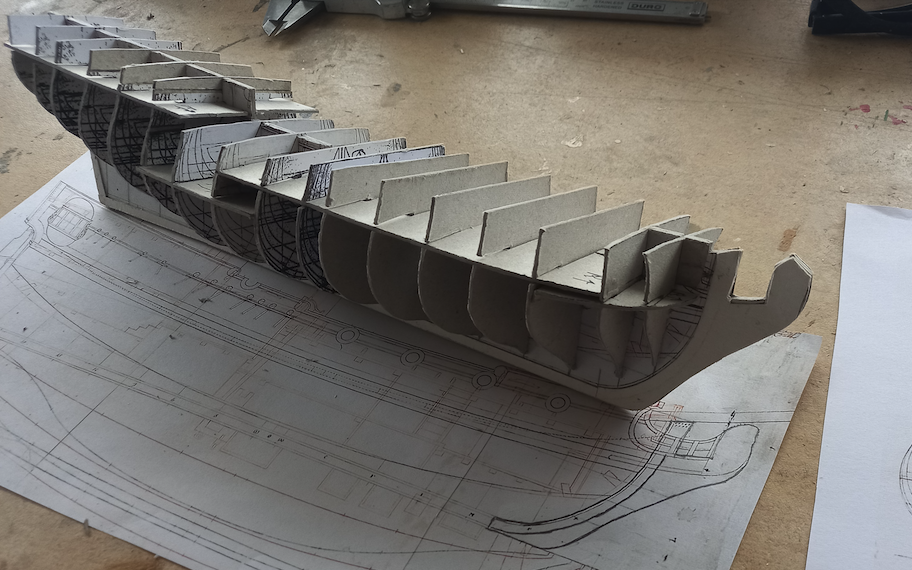
- 77 replies
-
- 12
-
-

-
- Royal Yacht
- card
- (and 1 more)