Search the Community
Showing results for tags 'sloop'.
-
 Welcome to this build log. If you're wondering what happened to the Queen Elizabeth galleon, I have postponed that build in order to do this. This will be a scratchbuild made mostly of wood, and I already have some comprehensive full-scale plans made. Remember Don, the man referenced in my Senora Fielden research log? Well, this is for him and his wife. Both are good friends of mine, and Don has seen the designs. My main goal in posting this log considerably before I plan on making sawdust is that I want to iron out some of the questions in procedure and perhaps design. This is the original prototype of the cutter build. While the arrangement of the deck will be considerably different, the hull shape and rig are functionally the same. The final length of the ship (bowsprit to spanker) will be around 3 feet, while the height is somewhere around 4 feet. The rig is subject to change. These are the plans as they are:

-
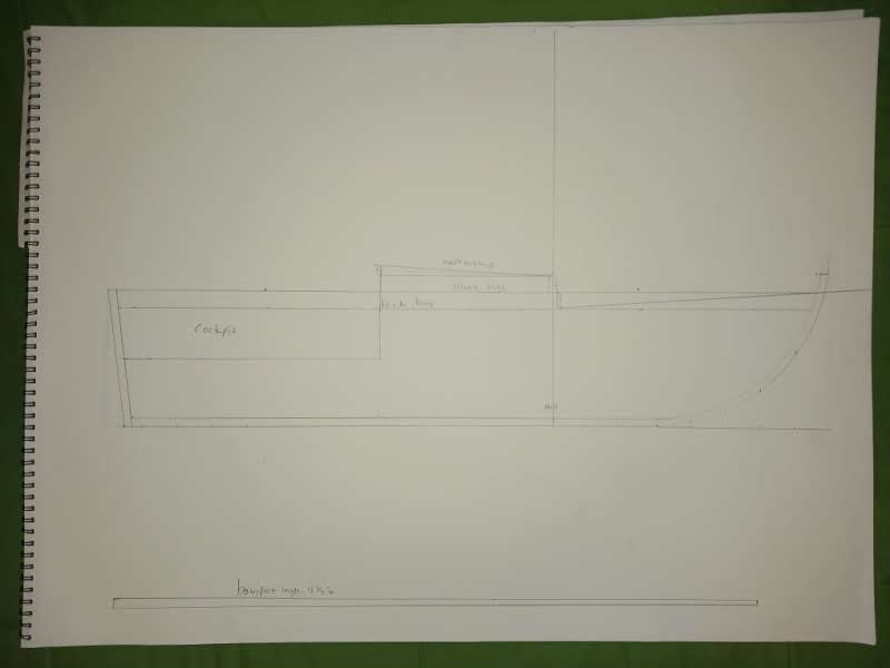
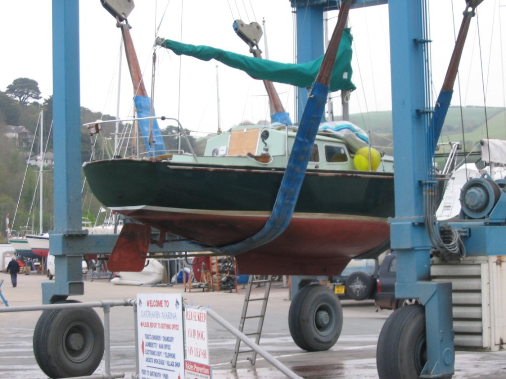
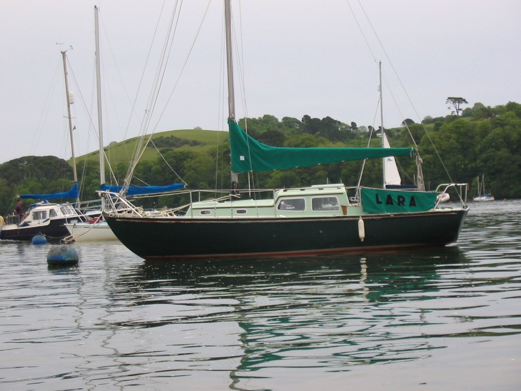
 I am about to begin building my first scratch boat. I was looking for a sailing boat kit that I could add RC to. There are some in the Krick range and I nearly plumped for Ariadne, but was wavering at the required skill level and cost when my son suggested building a model of our old boat that we had when they were kids. Brilliant! I knew where to get plans and have an intimate knowledge of every detail I'll need to pull this off. I contacted some old pals in the Trident Owners Association and within a day, had full lines, construction, section, sail-plan and other original drawing scans. They are at the scale 1.5 inch : 1 foot (1:8). The boat is 24 ft LOA so after converting that to metric, I'm going to end up with a model around 940mm LOA. I think that will be ideal to house RC and for her to sail in reasonable winds. I'll need the equivalent of 760 Kg of ballast in the stub keel (94 Kg to scale..I assume mass has the same ratio as linear measurements when converting for a model ? ) the rest of the 5 tonne displacement will need to come from the construction materials, RC and running gear, batteries and probably some lead shot in strategic places. The original boat was GRP with plywood bulkheads fore and aft of the deck-stepped mast and fwd of the transom. I'll add frames at most stations from something like 12*5 mm strips. The point of the bow fwd of the accommodation will be solid balsa. I'll plank with whatever is reasonable and available at the time, then cover the hull in several layers of fibreclass cloth and resin... at least they are the sketchy current plans.. Lara was 91 out of 248 Tridents built. Sadly the person I sold her to, abandoned her and she just rotted away as far as I know. I am actually still trying to find her after a last sighting 'in a sorry state' 10 years ago. Whatever the outcome, Lara will live on in this model. It isn't going to be a quick build I'm still working in parallel on a CUX 87 kit, I work full time and have a family, so don't expect many updates for a while. Plans and photos attached. sections.pdf 1974marconbrochure.pdf linesmall.pdf
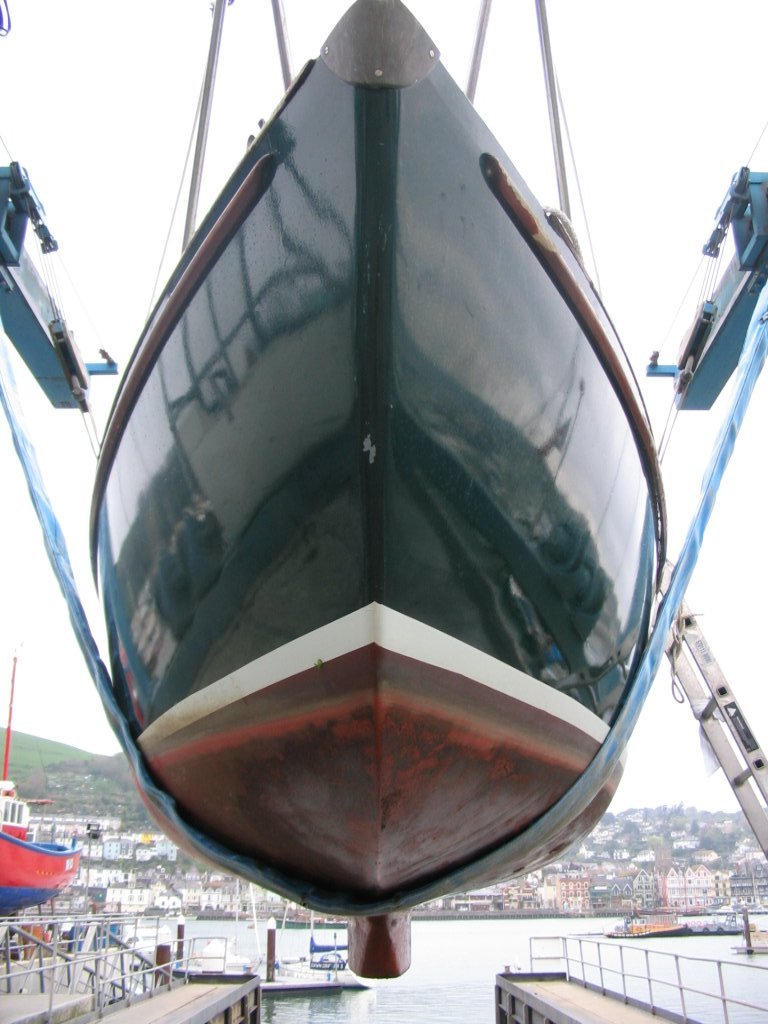
-
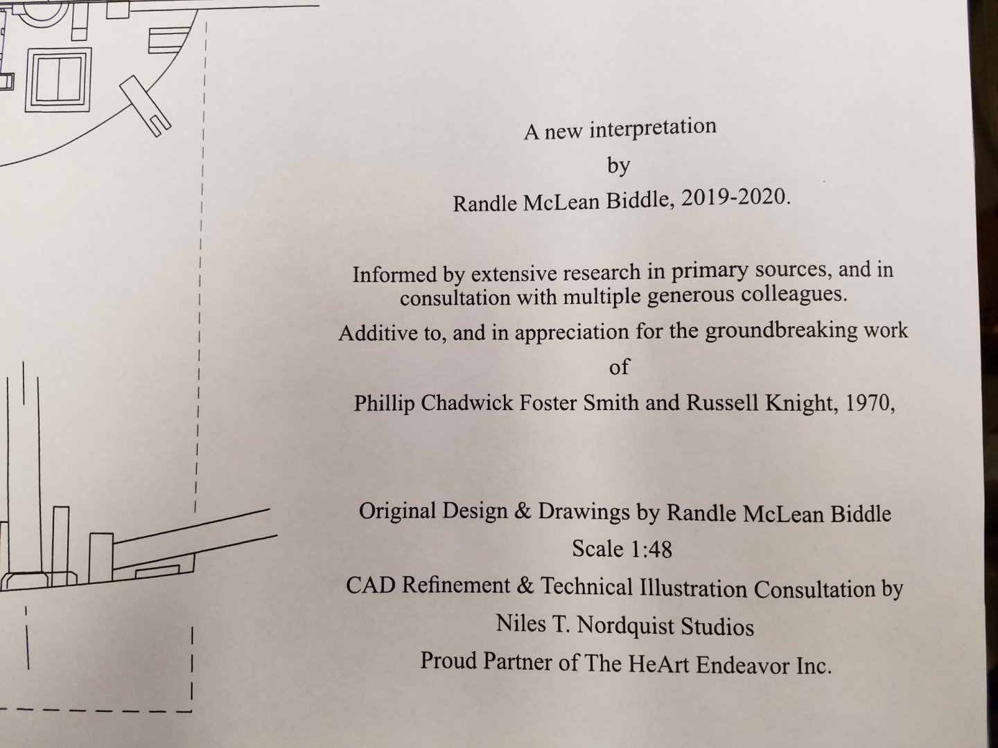
 Recently, I became interested in ships of the Colonial era. From a forum post about Chaleur I came across a lead to an extended article by Randle Biddle at the NRG. It discusses a his new design perspective about the Hannah. I found the article very novel and well thought out and it will be a great model project for me albeit a challenge. The article also includes plans by Randle Biddle: The plans are published by the Nautical Research Journal and are available to NRG members for download. That’s a great bargain and well worth the cost of joining the NRG. The plans consist of five sheets at 1:48 scale in jpeg format. I chose to upload four of the sheets to Staples blueprint service and they were ready the next day and look great. In a photo editor, the body plan was cropped into bow and stern half views then each mirrored and stitched back together to duplicate and cut up for station templates. This shot shows the significantly lower tonnage then Harold Hahn's plans. This will be a 1:48 scale scratch, plank on bulkhead model. I’ve seen some really great open-deck model versions and want to give that a try. This remarkable project by @tlevine of the Swallow 1779 will be a great resource for me to get through the planning pitfalls that I’m sure are coming my way. Comments, corrections and "watch out fors" always welcome. Mike
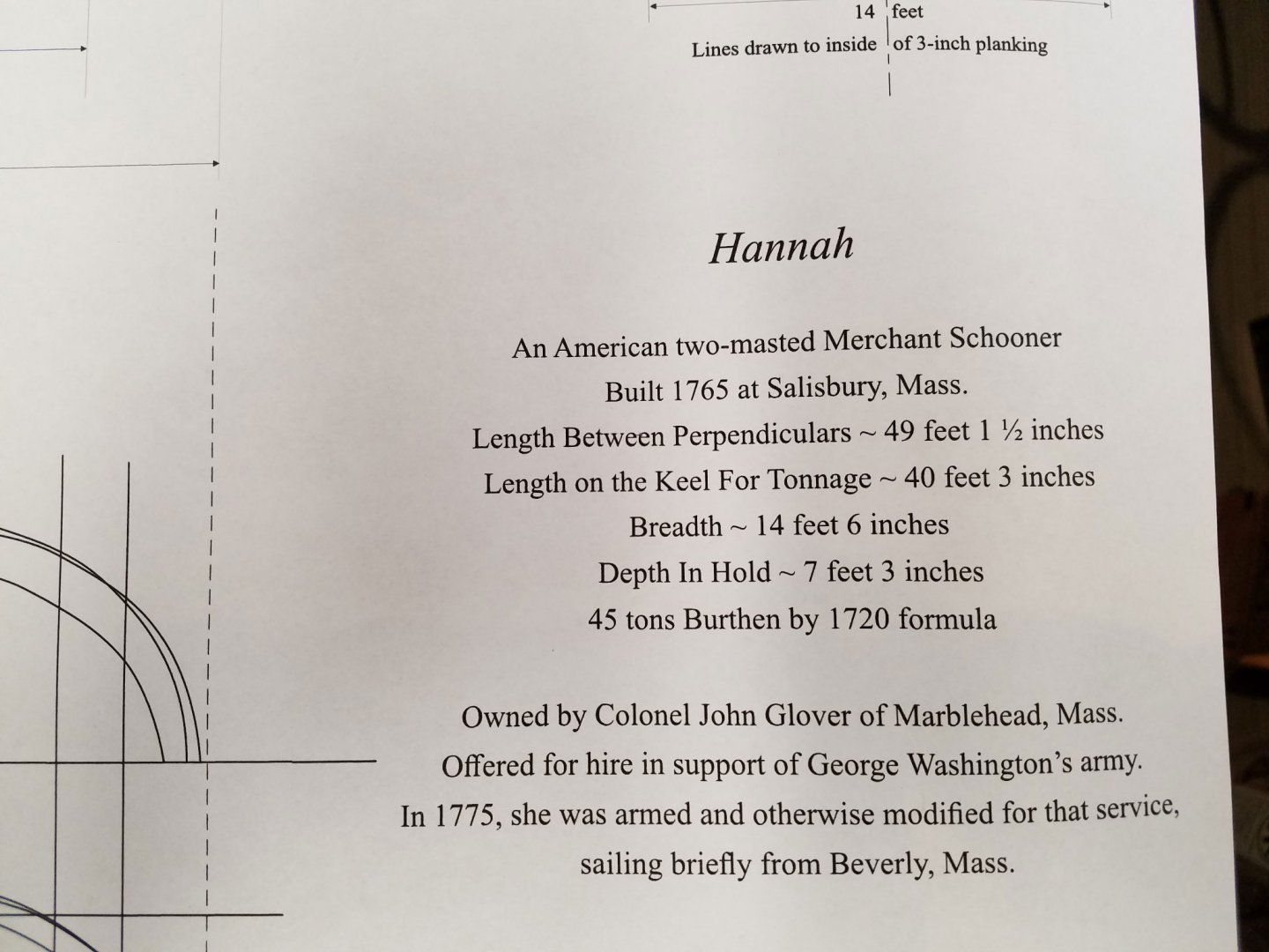
- 75 replies
-
- 10
-

-
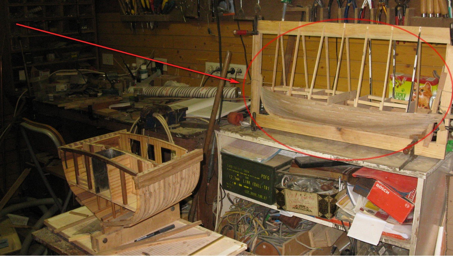
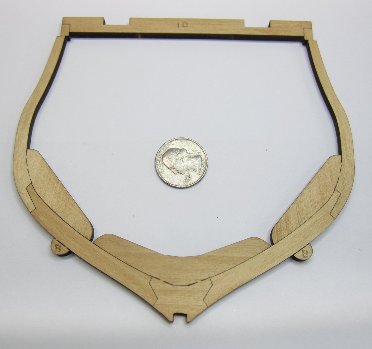
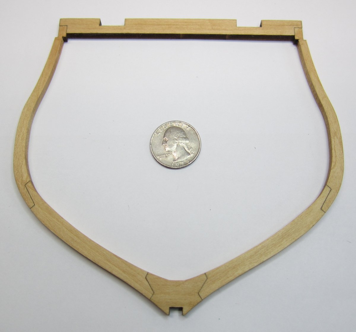
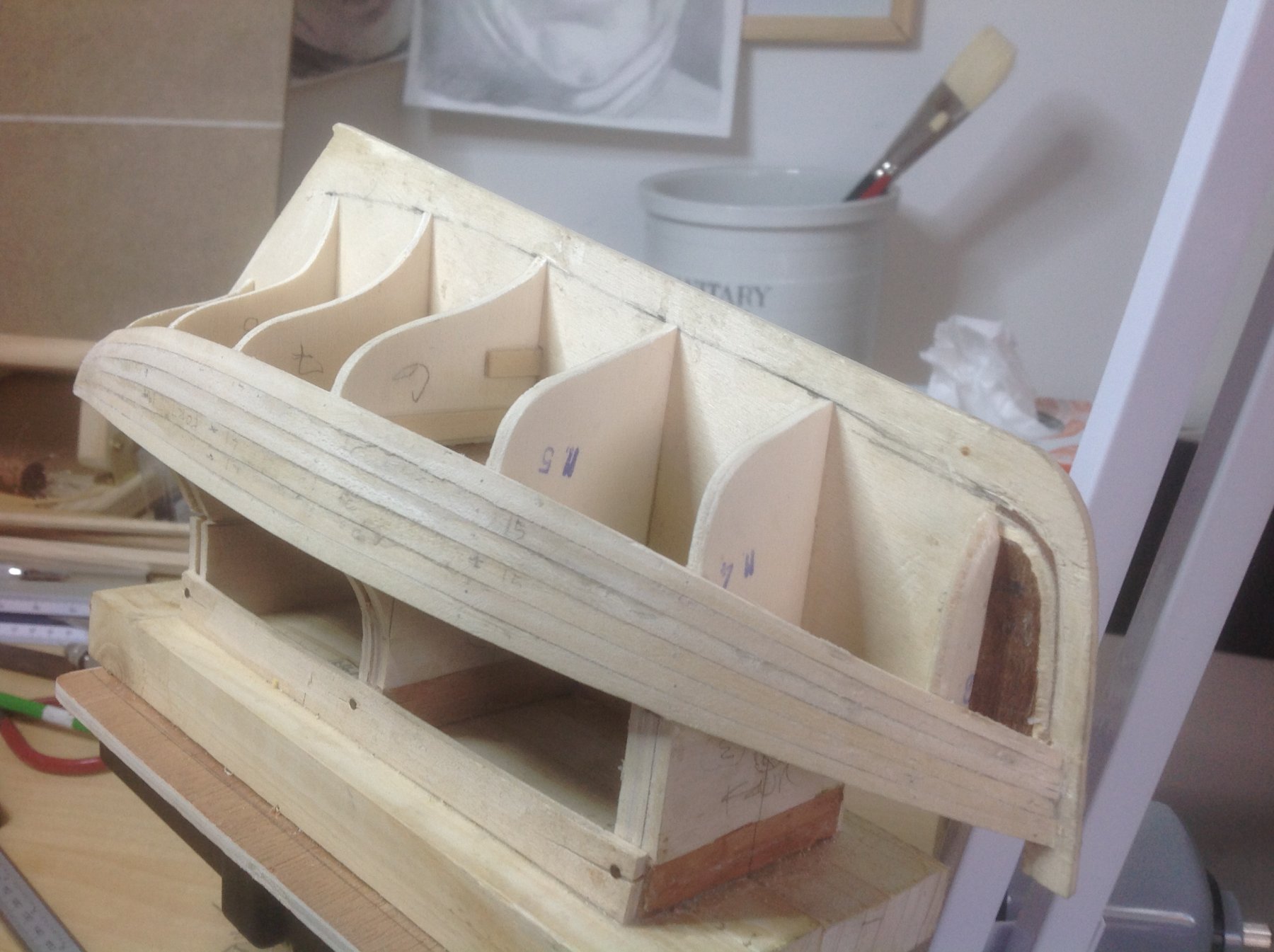
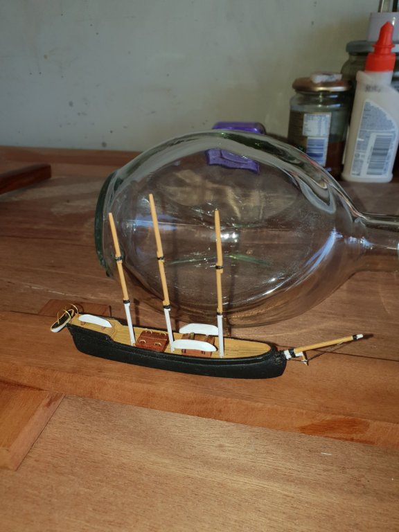
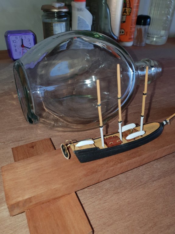
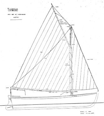
 Today I made the first cut for a model I have been planning an researching for a while. This will be a typical sloop from Roslagen (an area in the Stockholm archipelago and the coast north of it). Once, such sloops where a common sight along the quays of Stockholm, but from around 1920 they started to disappear quickly. They where typical working boats and where usually not built on a shipyard. Instead they where built by the fisherman/framers on the islands of the archipelago. Maybe with the help of a master ship builder that was hired to help with the critical laying of the keel and forming the strakes and fitting the frames. Then the builder/owner used the ship for his own needs, and for transporting goods to the growing city Stockholm. The hulls where (with few exceptions) clinker built using traditional methods following principles that goes back to the viking age and beyond. Looking at the hulls they in many ways resembles enlarged open boats. And it seems to be the way that they had evolved. For the inhabitants of the archipelago there was a need for different sized boats for different tasks. So the same shape was more or less reused in different sizes. This model will be of a "Storbåt" (= great boat) or "Sandkil" as it was also known. The later name is derived from "transporting sand" and became the most common name as they where used for that during the late 19th century when Stockholm was growing rapidly and many houses where built. There where also larger variants, such as the "Vedjakt" (firewood yacht) that specialized in transporting firewood. My model will be based on a plan from the Eskader (eskader.se) hobby shop in Stockholm. The plan is, as far as I can tell, not based on any specific ship, but is a generalization of the type. It does resemble the following drawing quite a bit, so I think that that has been the primary source. The drawing above is from the collections of the Maritime history museum i Stockholm. The text under the title says that it is based on measurements of a real ship. However it does not say which one and when it was done. I do suspect that it was made somewhere between 1930 and 1950, while there where still some ships left to make measurements of. In the 1970s it was believed that none had survived. But then in the 1980s a hull that had been converted to a houseboat was discovered and renovated. I will use the photos from that renovation (which are available at Maritime history museum) to fill in some of the details that are missing in the plans from Eskader. What I miss most from the plans is any indication of the shape and position of the frames. My plan is to build the model as a traditional clinker built boat, shell first, upside down over a plug. The frames will be installed after the shell is complete, so I have some time to continue my research of where they should be placed. The first step will be to cut out the centerpiece of the plug, and then use that as a guide when building the keel. This is an approach that I picked up in Wintergreens log of Kågen. Cheers
.jpg.cd54a7cfef4108ce8d739b90836f2505.jpg)
-
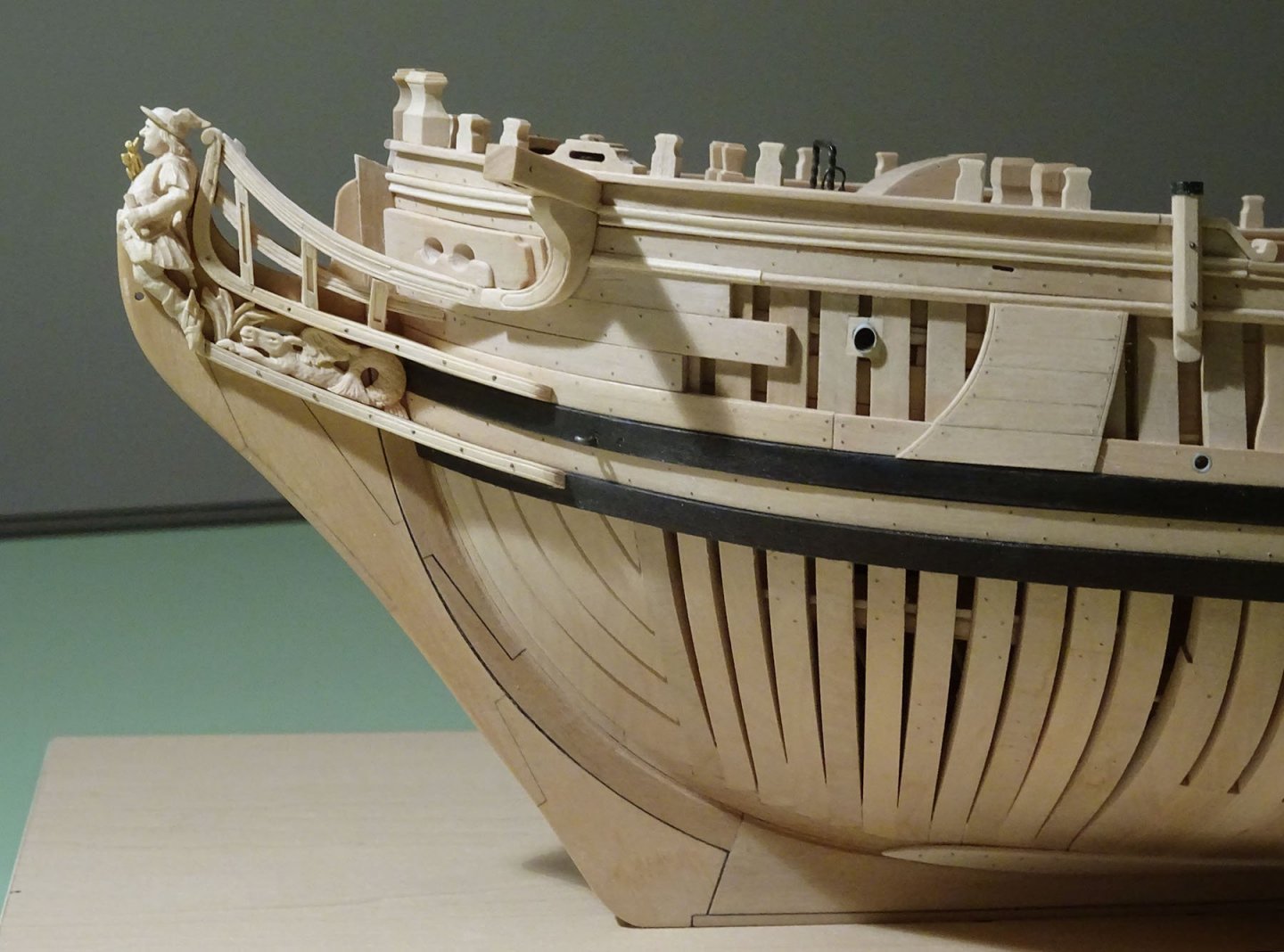
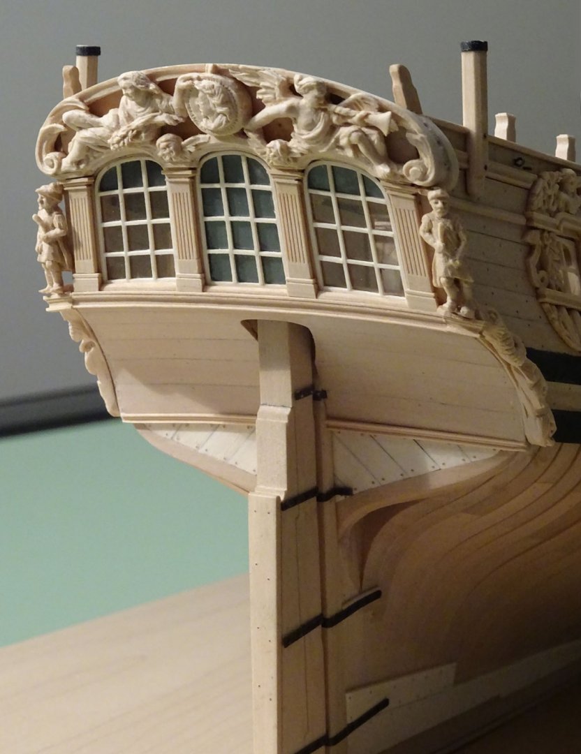
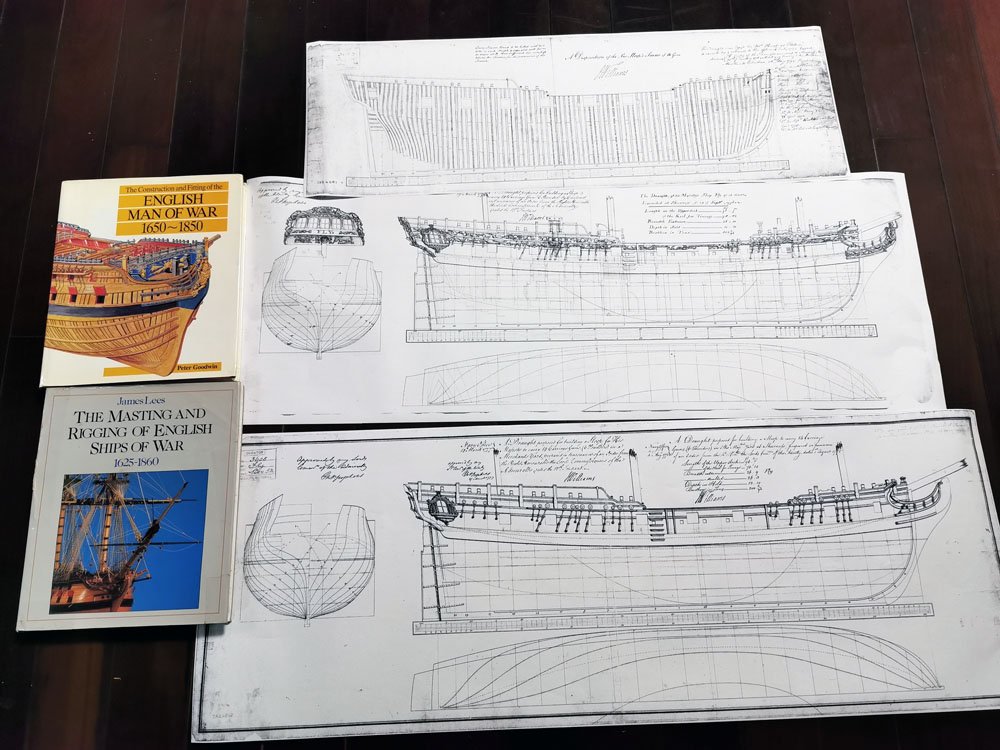
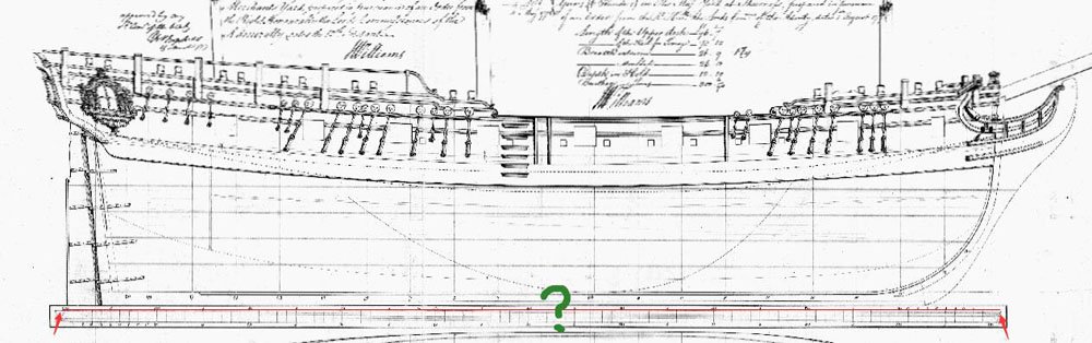
 Mediator was a single masted merchant sloop built in 1741 or 42 on the Virginia shore of the Chesapeake Bay. Purchased for use by the Royal Navy in May 1745 and lost less than three months later, she was caught up in the great affairs of the Jacobite Rebellion. In those three months she was in and out of the Mediterranean; captured by the French privateer La Naiade off the Needles; retaken the following day by HMS Assistance. After repairs she was quickly recommissioned and joined the convoys supplying the English land forces in the War of Austrian Succession. She foundered in Ostend harbour on the 29th of July and was lost just days before the siege of that city began. Dimensions: 61’ 4” length on deck, 44’ length of keel for tonnage; 21’ 2” breadth for tonnage; 9’ 9” draught and 104 74/94 tons bm Crew: 60 - 80 at different times Armaments: 10x 4 pounders, 18x 1/2 pounder swivels Plans of Mediator are in the NMM, id number J0569, see image at beginning of post: https://collections.rmg.co.uk/collections/objects/86159.html … although it would be possible reading the description of the plan to believe that Mediator was built at Portsmouth: she was not, but the plan was and that is what is meant. Chapelle also re-drafted plans for Mediator, see The Search for Speed Under Sail, plates #10 and #11. IN 2013 Jeff Staudt produced plans for a model of Mediator in collaboration with Winston Scoville. They are downloadable legitimately: http://modelshipbuilder.com/page.php?192 The 1/48 scale plans are in PDF form and print out on seven A1 sheets. They are superbly detailed drawings and apart from a few comments there are no instructions per se. At 1/48th scale the length overall will be 779mm, approximately 30 ¾ inches. Looking at all the plans together, a couple of points become evident straight away. Mediator was pierced for 14 guns but the stated armament was ten: even that figure may be excessive as it is unlikely the full compliment of arms was carried while in convoy service. The crew figures I have found also seem high (60 to 80) but perhaps reflect those times when she was an independent merchant ship and needed all guns and of course gun crews. Unless I lose my favourite marbles, I will build Mediator as per the drawings. The only planned exceptions to this are details, such as to substitute metric standard plywood sizes for the main former and bulkheads, the addition of a capstan and some changes in the deck layout and planking, more on that later. Planned materials: woods = ply, cherry, castello boxwood, apple, holly; other materials = brass, card, paper and miscellaneous bits as inspiration requires. There is a back-story. I have never made a wooden model ship. After years of planning to build HMS Pickle from scratch, when the time came to start making sawdust my expectations (thanks to MSW) had grown to the point where the bar was much higher than I could achieve with my untested skills. So, as a part of the learning process, I decided to make at least some of my mistakes in a safe place. I am making Mediator as a sacrificial model that will allow me to rehearse processes that are new to me and (hopefully) still have something acceptable at the end of the exercise. In other words, I am going to build a model before I build the one that matters to me. Since this is a hobby, not a career or a marriage, it is worth admitting that I felt better about the Pickle project as soon as I took the pressure off by doing Mediator first. Who knows? With plans of such quality as a starting point I may end up with a decent model. If not, it will be down to me as there is nothing wrong with the plans. So, here goes. Sawdust begins in post #2.
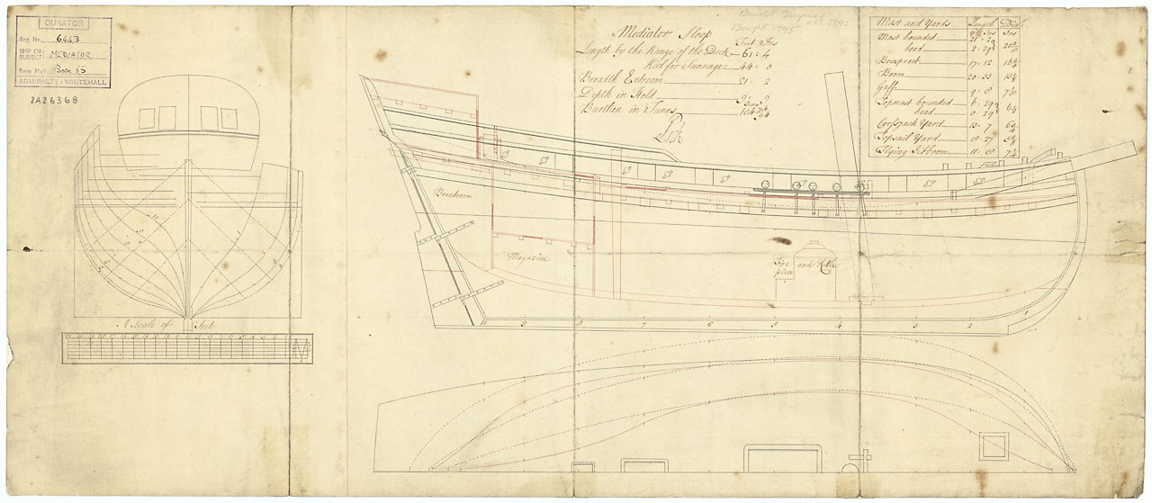
- 43 replies
-
- 5
-
-
- mediator
- first build
- (and 1 more)
-
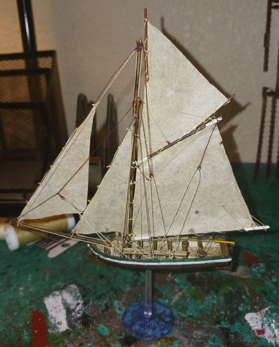
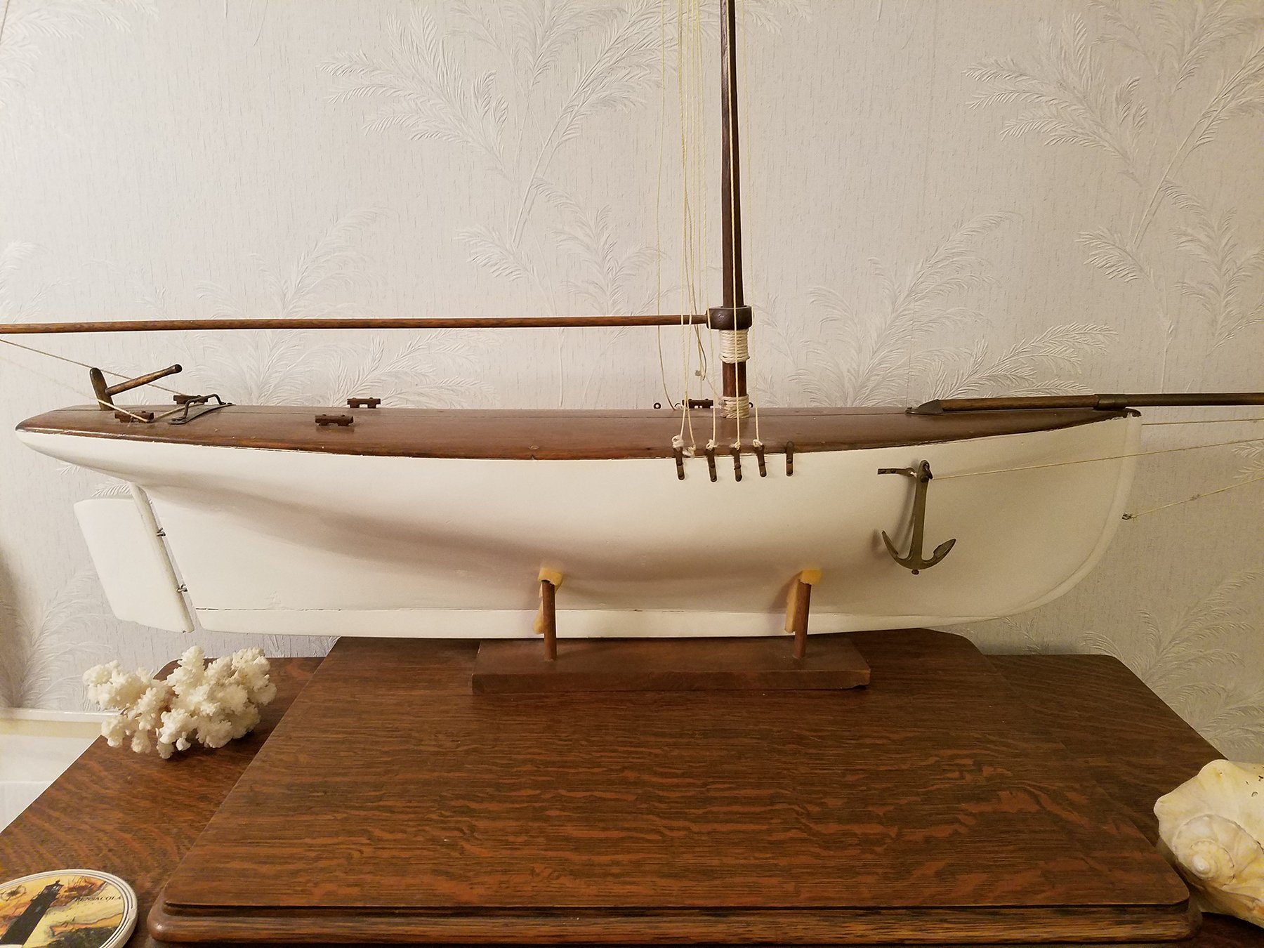
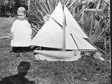
 Hello All, I have a model that was built by my Great Grandfather for my Grandmother back around 1913. Dad and I decided top rename it Virginia Ruth, my Grandmothers first and middle name. It is supposed to be modeled from a sloop(?) that he was familiar with in the Gulf at Homosassa, Fl. Way back in 1980 or so, I did a cosmetic rebuild for a 4-H project. I want to restore it to how he built it. The hull is hollow and we think it may be made out of Bald Cyprus. All I had to work with was the hull and a photograph. My grandmother said that all the rigging operated as it was supposed to, but none of that is left. He used pulleys and other hardware sourced from England. I guessed on the mast height based on measuring the photo and the actual hull. I repainted it, and stained the top for more of a deck feel. I am open to modifying the ship to make it as close to how it would have been in reality. Most of the hardware on the deck is original and I do have the anchor. The hull measures 32 1/2" long on the deck. it measures 6 1/2" tall at the mast. Here are two photos when it was new. My Great-Grandfather's shadow is visible. Here are two photos of how it looks now. Pretty much a butcher job as I had no idea what I was doing. I am willing to replace and add what hardware needs to be added. I have a set of sails for it that were made from measurements and drawings of the original photo and measurements of the hull. I really do not like the metal bits that are used for deadeyes or maybe in this case turnbuckles. Let me know what you think and don't hold back. Thanks, Russell M.
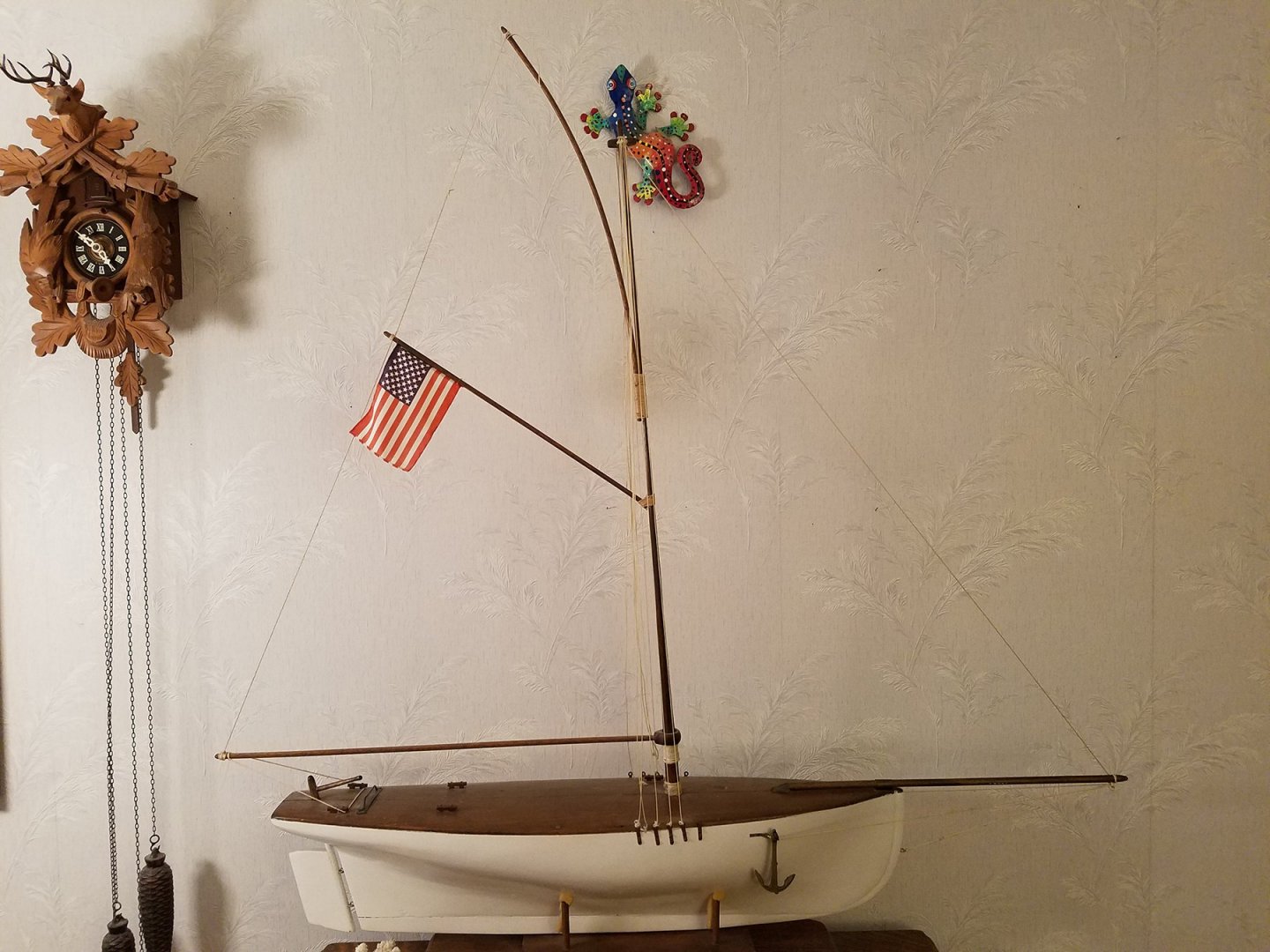


- 21 replies
-
- 7
-
-
- virginia ruth
- sloop
- (and 1 more)
-
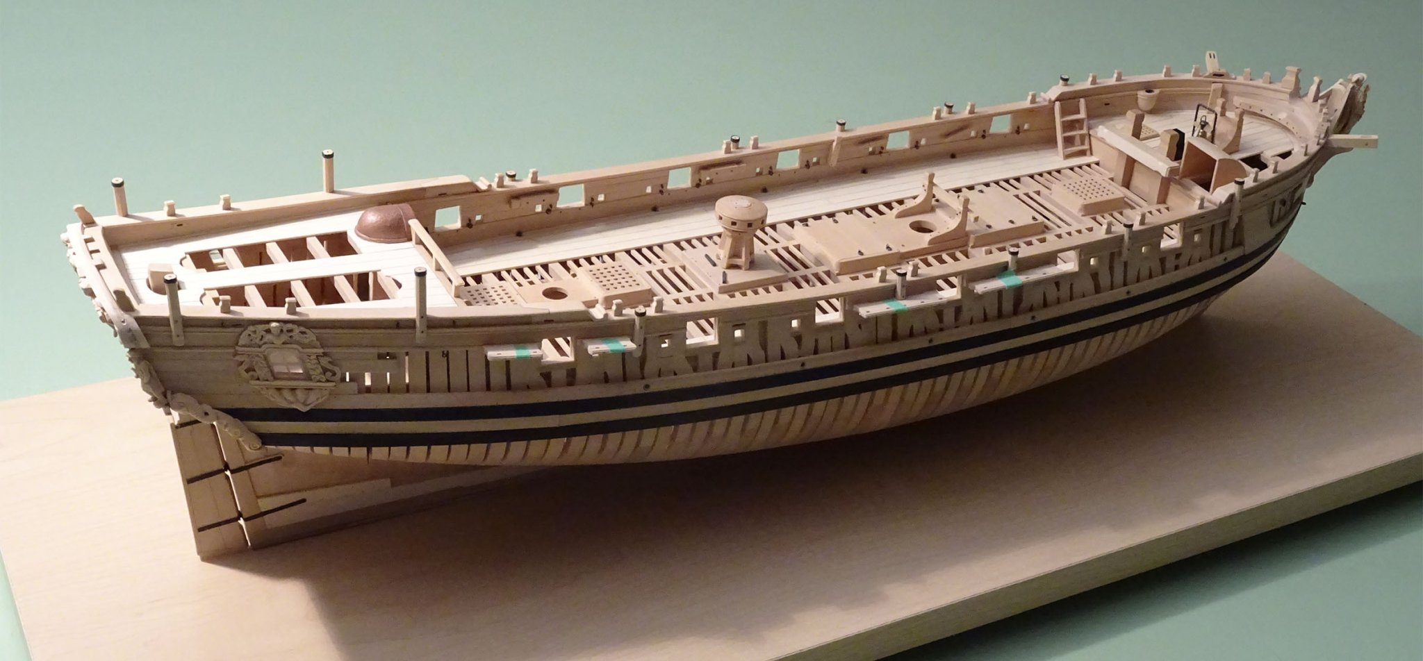
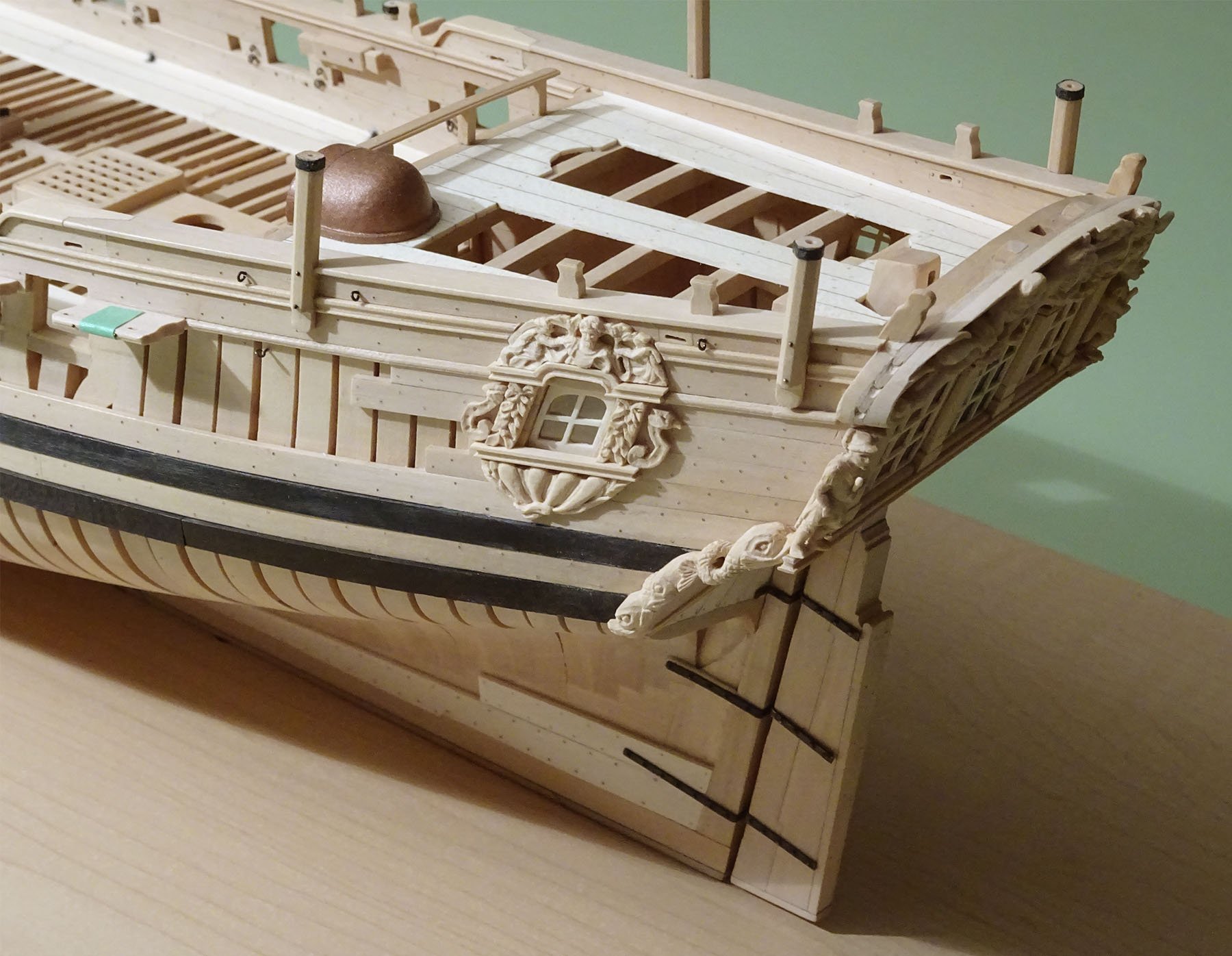
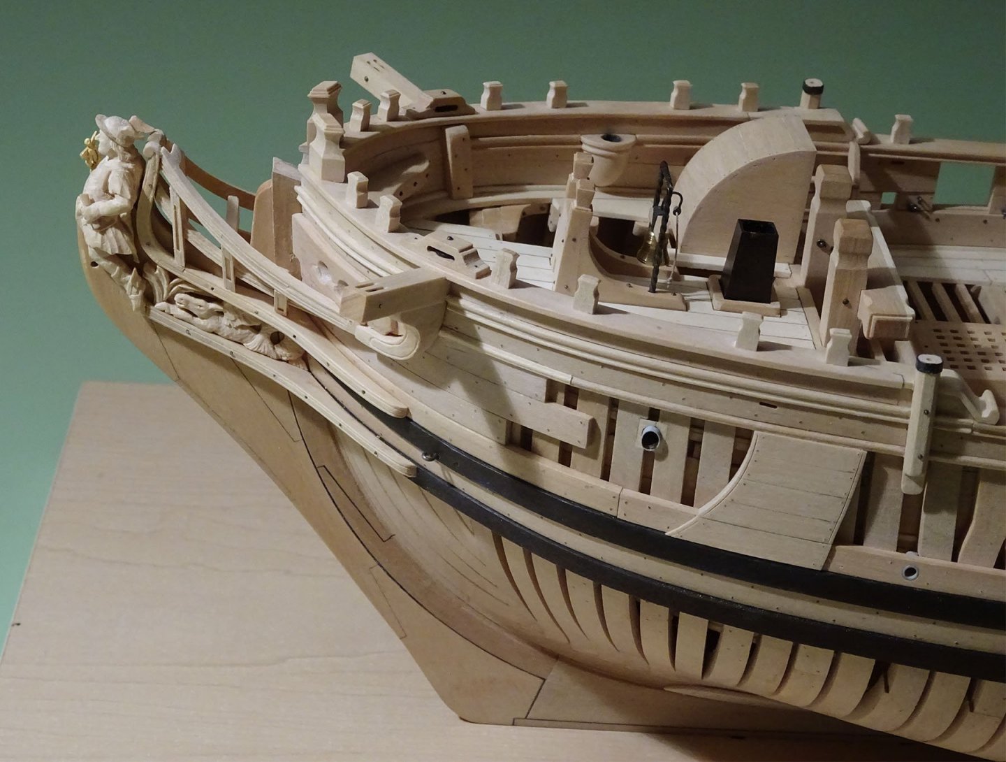
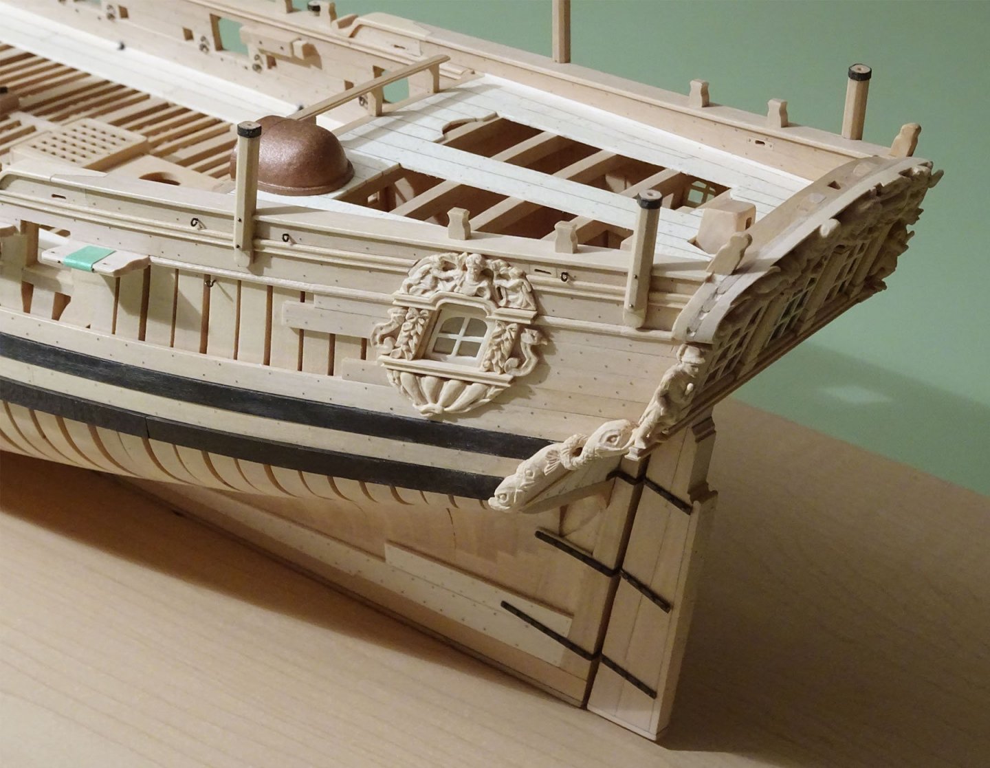
 This model at 1:48 scale and the subject of two volumes, is progressing well. Greg Herbert has almost completed the hull and fittings, while David Antscherl has provided the decorative carved works. Masts and spars are also currently under construction by Greg. Woods used in the model are Castello boxwood and holly. The model will be on display at the North-East Ship Model Conference, New London, at the end of April.
-
I was shocked when I saw this set of drawings for the first time. He was so gorgeous and had so many beautiful paintings. I watched for a long time and slowly appreciated them, trying to understand the craftsman's state from my current perspective The ribs of British wooden sailboat are very complex. When making HMS enterprise, the ribs are simplified. There are two advantages: 1. The difficulty of making is reduced, the production is convenient, 2. The cost is reduced But for HMS fly, I want to show its original structure as much as I can, which is a big challenge for me, but I like to challenge Here's the scale, which can be adjusted to any scale
- 59 replies
-
- 14
-
-
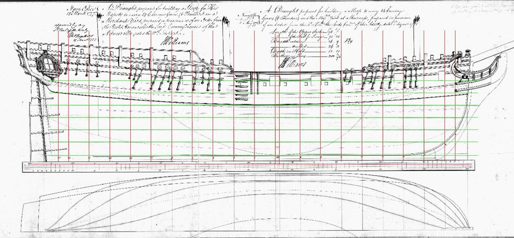
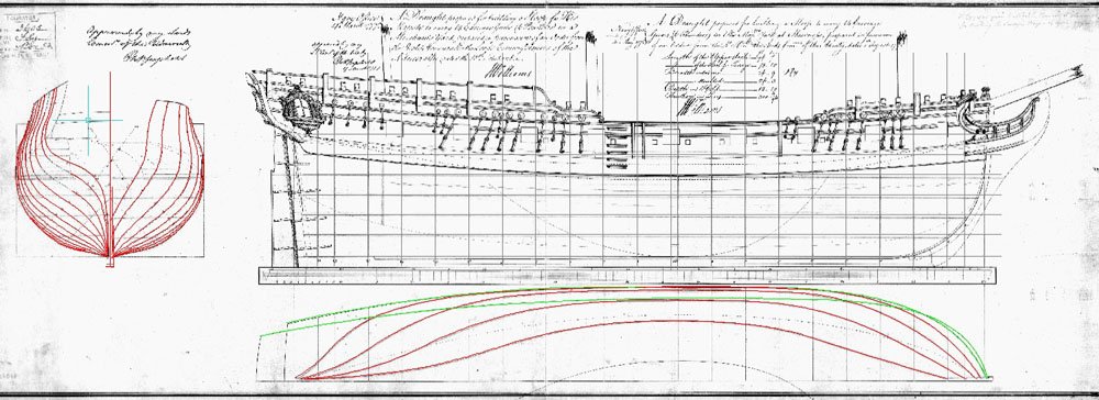
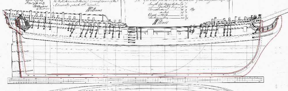
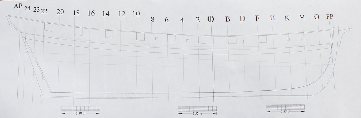
 A few years ago, I was looking at some of the models posted on the RMG website and came across Swallow 1779. I instantly was attracted to her overall appearance and the fact that she was clinker-planked. The model is listed as SLR0540 and the plans are ZAZ4719. Swallow did not have a long career. According to Rif Winfield, in his book “British Warships in the Age of Sail 1714-1792”, she was purchased on the stocks in 1779 and was originally designed to be a cutter. On the sheer plan one can see where the original mast (located at the dead flat) was erased from the plan. She was registered as a sloop and originally carried fourteen 4pdr guns. The following year, four 18pdr carronades were added. There is no mention of swivel guns, although the plan shows mountings for twenty-two of them. With Lively, Swallow captured the US privateer Black Prince in 1779. She was coppered in 1780 and on August 26, 1781,, Swallow was run ashore and burnt to avoid capture by US privateers off Long Island. The first order of business was to develop a set of plans. Comparing the plans with the model revealed several inconsistencies. Starting at the bow, the model has a much larger stem with cheeks, rails, a false rail and a figurehead. The bowsprit come out of the hull in the midline. The plans show a simple stem and the bowsprit exits the hull to the port side of the stem. The model shows the capstan at midships but the plan has it aft of the main mast. The locations of the various hatch covers also differ between the model and the plan. There is a difference in the deadeye configurations and the swivel guns are not modeled. Finally, although the gold detailing is stunning, this little boat certainly would have never been decorated in other but the simplest schema. To make things even more confusing, in small print on the plan is the following..."a copy of this was given to Mr. Ladd for finishing two cutters the Board bought of him when half built 9 Feb? 1779". And, yes, the question mark was in the sentence as written. So the plan is actually the proposal for finishing and not as-finished. I had to decide whether I was going to model a model or model a ship. Because the model is most likely a presentation piece, I decided to use the plans layout rather than the model's. This still left me with concerns. The biggest one was whether to model the swivels. Since the model does not show them and Winfield does not mention them, I decided to leave them off. There is also no "proper" access to the lower deck on the plan but a companionway is visible on the model. I have added a ladder and companionway. If any of you have additional information or insights to the contrary, please let me know. Things are easy to change at this point. This was going to be a plank on bulkhead model. My reason for this construction style was that the beauty of this ship will be in the clinker planking; therefore, both sides of the hull will be completely planked. I will be installing the lower deck and its associated fittings in the mid-ships area as I plan on making the hatch covers removable. Plans were developed using the tutorial written by Wayne Kempson which is found in the Modeler’s Database. http://modelshipworldforum.com/resources/plans_and_research/DraftingShipPlansInCADwayne.pdf TurboCAD 18 was my CAD program. Once the plans were developed I made a half hull in 1:96 scale to make sure that I did not have any glaring errors in my rendering.
-Warship-Brig-Sloop-14-guns-0a.jpg.e3f885d62571cfd7901348984918a400.jpg)
-Warship-Brig-Sloop-14-guns-1a.jpg.b44bc9297c470b4b90d66c3e240c9029.jpg)
- 277 replies
-
- 32
-
-
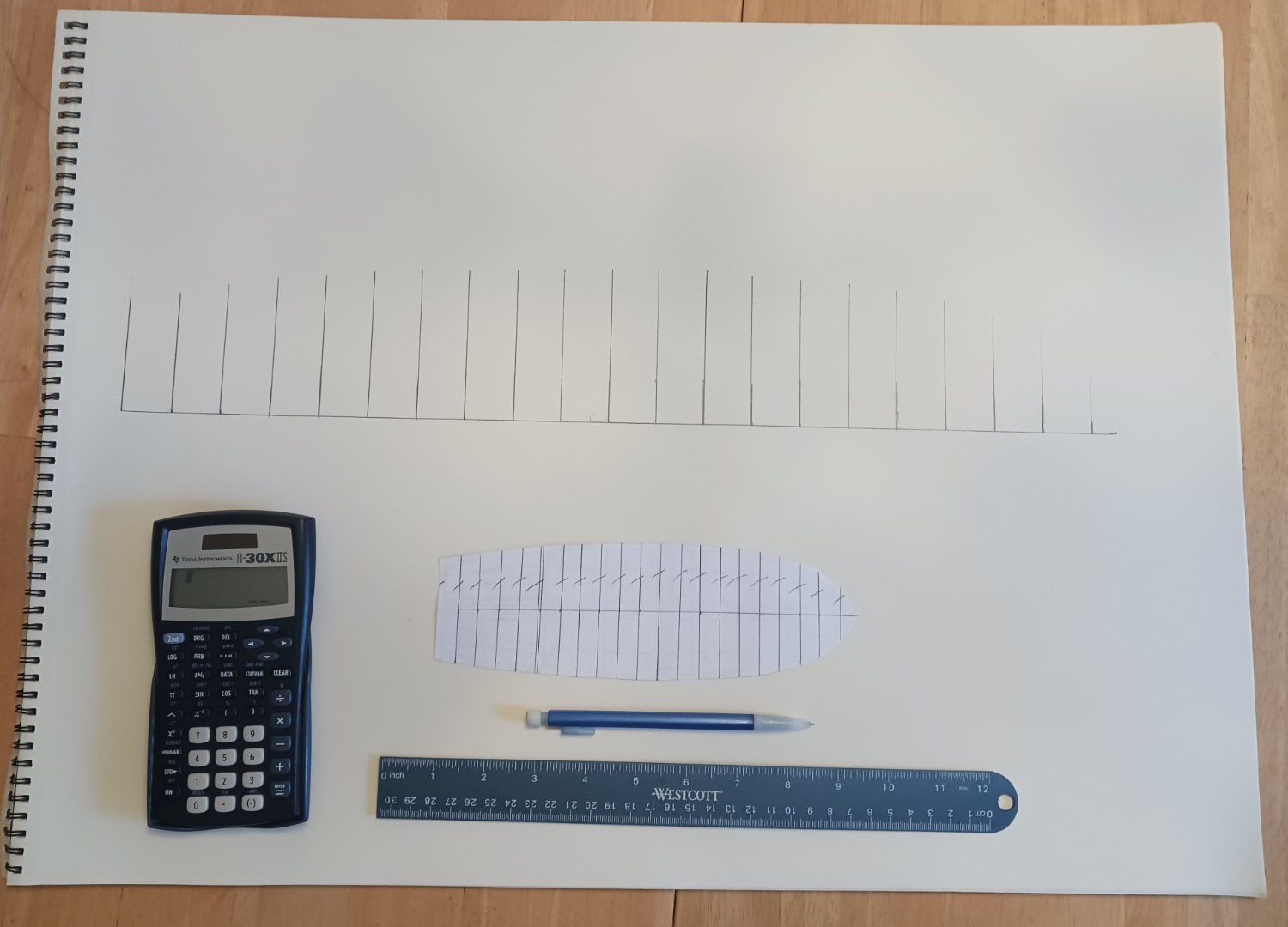
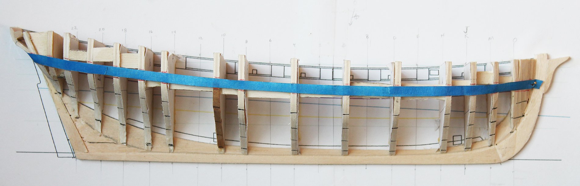
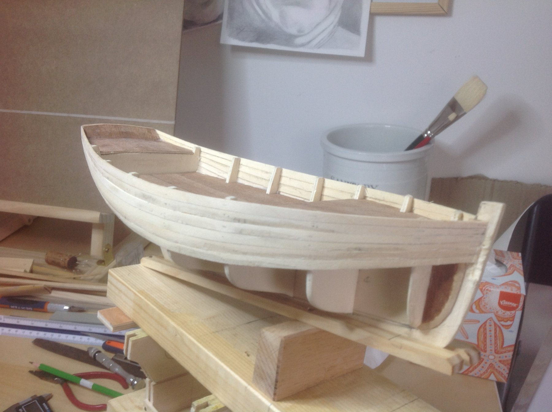
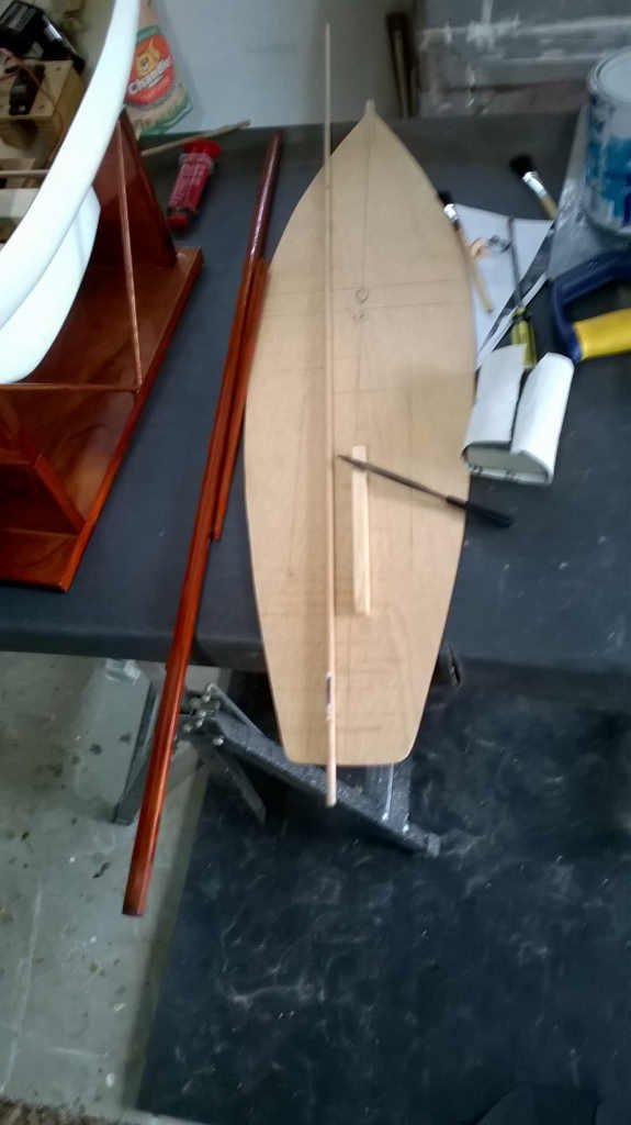
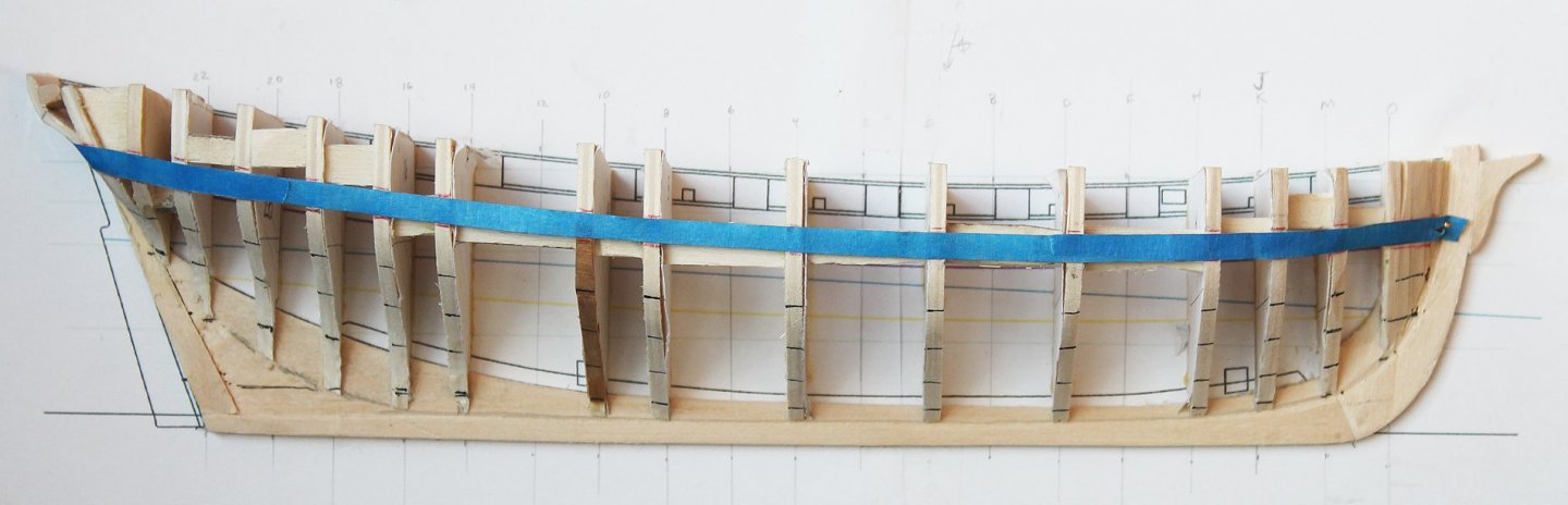
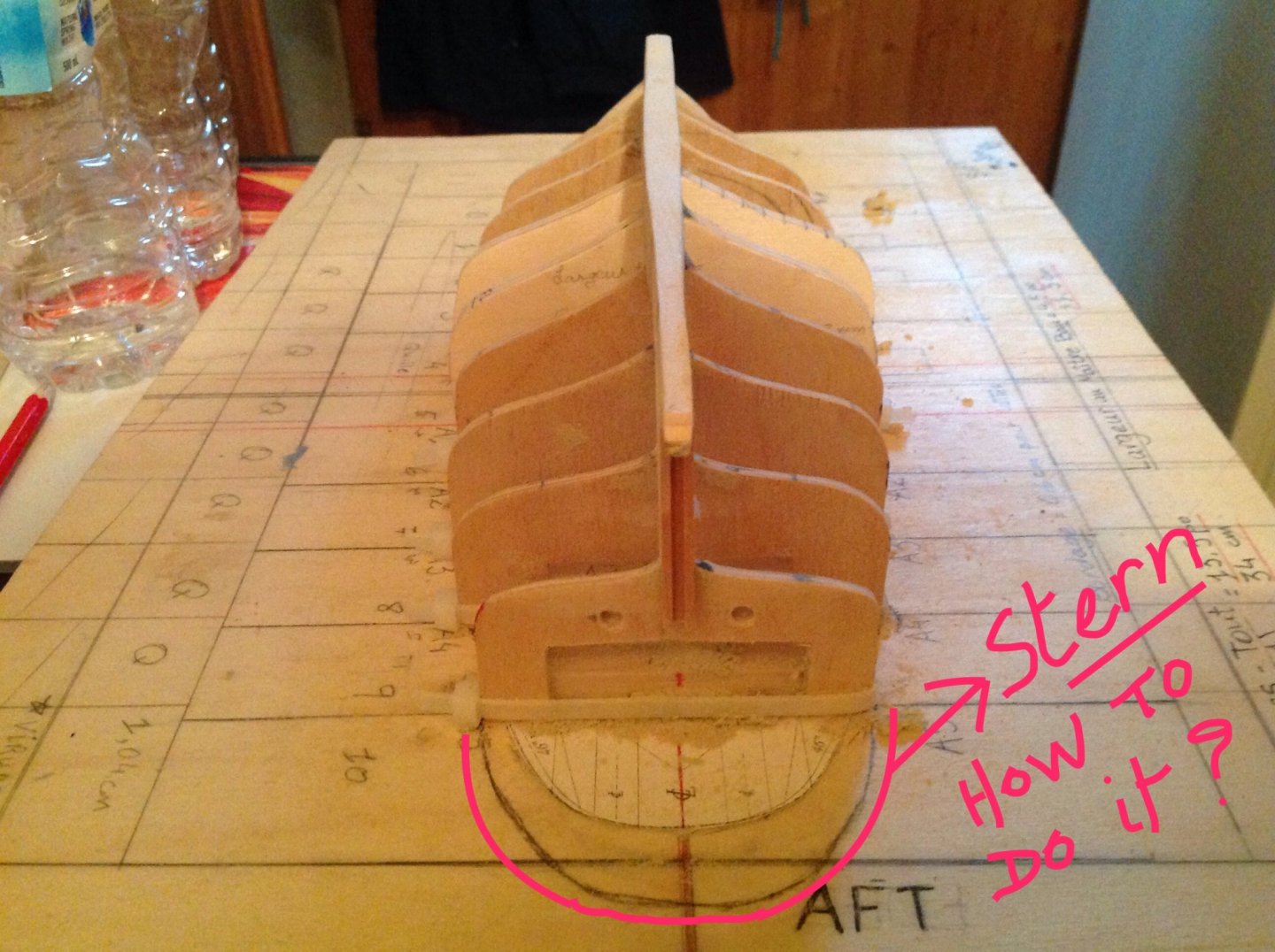
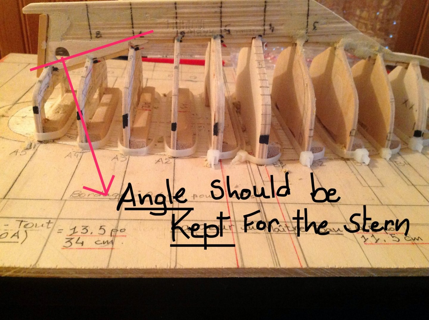
 Hello everyone, I will describe the building of my little boat, but before, here is a short (euh... ok, everybody has not the same concept of what is "short" 😜 -- mine is like a rubber band ! 😂) story of the KATHLEEN. I will come back to describe the building and put some photos very soon. I have begun it in July, and it was following my fifth failure upon other boats’ projects that were too ambitious for the “rookie” I was in ship building. I put aside my pride 😂 and decided to get involved with an easier project : the shoal-draft centerboard Sloop named KATHLEEN which has been built on North-Beach in 1904-1905 by the immigrant boat builder S.O Pasquinucci for Frank Raymond, a grocer that named her for his daughter, born in 1903. The Sloop has been used both for cruising and racing, until the First World War, in 1914. Rendered obsolete by changes in racing boat rules and designs, the boat has been altered into a yawl with ballasted keel in 1930 and was then used for recreation for seven decades. She had many owners after Raymond who killed himself on February 27, 1913 with a shotgun after some business troubles. He was then 36. The Sloop is an example of the national yacht type that dominated most American yachting centers from the 1850 to about 1885. These Sloops developed from beamy craft with lofty, single-mast rigs that the Dutch used on the shallow waters and transplanted to New-Amsterdam in the XVIIth Century. New-Amsterdam was to become New-York more than a Century after. The first centerboard (generally 15 to 24 feet in length at the waterline) arrived in San Francisco about to 1850. They were intended as workboats for fishing and freighting, but they doubled as some of the bay’s earliest recreational racing boats. An interest in amateur racing spread among people of moderate means, such as clerks and attorneys who owned and maintained their boats with volunteer crews. They then formed yacht clubs whose name incorporated the term “Corinthian” for their amateur status and reliance on unpaid crews. The KATHLEEN broke her mast on her very first time out in April 1905 and had to have a new mast stepped. It was replaced in March 1906 by a shorter one, and the gaff was lengthened by 8 feet to carry a high-peaked mainsail. A new centerboard was fitted and the cabin overhauled at the same time. In February 1908 owner Frank Raymond had the 1906 mast replaced with one six feet taller to accommodate a new set of sails for the coming season. In 1931 the owner Edward E. Shea, also member of the Corinthian Yacht Club as Raymond was, installed the first auxiliary engine. The power rating is unknown. To do so, the companionway was repositioned to starboard. Edward C. Thoits, a well-known civic leader purchased KATHLEEN in 1932 and changed her name to ISLANDER. He owned her until his death in 1951. In 1992, Stephen Canright, a curator at San Francisco Maritime National Historical Park (SAFR) noticed the boat in Paradise Cay Yacht Harbor and recognized it as an example of an historic yacht type that was almost extinct in San Francisco Bay. Canright created a syndicate for the boat’s preservation. Harry Smith, the owner of KATHLEEN who bought her in 1960’s, supported Canright’s view and help him out. However, the syndicate was loosely organized which weakened preservation efforts. In 1996 a substantial leak developed when a garboard seam opened up during a trip. The boat was repaired but extensive cruising in her was given up before 2005. Smith donated her to SAFR in 2011. The Historic American Engineering Record (HAER) is a long-range program that documents and interprets historically significant engineering sites and structures throughout the USA. HAER is part of Heritage Documentation Programs, a division of the National Park Service, United States Department of the Interior. The Sloop KATHLEEN Recording Project was sponsored by the San Francisco Maritime National Historical Park (SAFR). Documentation for HAER was directed by Todd Croteau, HAER staff architect, Washington DC, under a cooperative agreement with the Council of American Maritime Museums. That was the story of the KATHLEEN, and how I have found her plans on the Library of Congress’ archives https://www.loc.gov/item/ca3967/ By the way, if someone is living in San Francisco and could go at San Francisco Maritime National Historical Park to take some photos of the restored KATHLEEN, and send those to me, I would appreciated it a lot for the photo they have taken are not so detailed. The building of the KATHLEEN : I began my project with the preparation of a board to build my boat with keel upside down. Then I have cut my Half Breadth Plan out and pasted it on to the board. Upon every line that embodying a frame, I pasted battens that I have used to tie every frame upon it. The photograph I put here will show you what I mean. My board is kind of muddled (i.e : borders are not very straight ; I have written on it, etc.) but the main purpose is reached. However, it was important to trace the middle line of the boat for laying the keel in a further step. Then I have used the Body Plan of which I have made 11 photocopies and I cut every shape of the frames (there is 2 midship frames for the KATHLEEN) which I glued onto a plywood with double faced tape, and I have cut it with my scroll saw then tie it upon the battens with tie wrap : I did not want to glue it because I wanted to be able to take it off if needed. The third step was the building of the keel. It was not an easy thing, especially if it slips from your grasp and the trailing end broke at the point of you are not able to recognize the parts !😭 But once more, I did not let myself being discouraged and I have built another one – which is far better than the first one ! I have used my Half Breadth Plan and cut the shape of the keel out of that plan five times and like the frames, I glued it altogether and cut it with the scroll saw before sanding it to have the right shape. I let a hole for the stern propeller (which I will installed when hull will be finished). Unlikely the former keel, I did not planked it, preferring doing that with the hull later The fourth step was to groove the rabbet to put each fram in the keel (I mean not the one used for the garboard – I should admit that I forgot it 😳) and this too I have had to do it again for it was not aligned the right way. I patched the rabbet up using Plastic Wood that I mixed with white glue for prevent it from disintegrate the very first moment my file would have touched it. My idea was a good one : it was cement-like and new rabbets were right and aligned. I would have thought that it should have been much more difficult, but it was the most easiest thing I did with that boat ! The keel was mounted in a perfect way when I have tried it that I did not dare to touch it and I decided to glued it without take it off in case of I would not have been able to put it right another time. Therefore, I have asked my dentist to give me a syringe with its needle for being able to put glue in the little cracks between frames and keel. There too my guess had worked. (Photograph : the former keel) The next step will be the planking, but however I have a little problem for which I hope you will be able to help me out with your experience: the last frame at the aft end is not the end of the KATHLEEN for she has a round stern which has an angle if you look at the plan. I know that I must do that before planking but I have not a ghost of an idea how to do it. Of course, I thought of some solution, but none had worked (the holes into the last frame can express it) and it’s been 2 weeks now that I racked my brains.
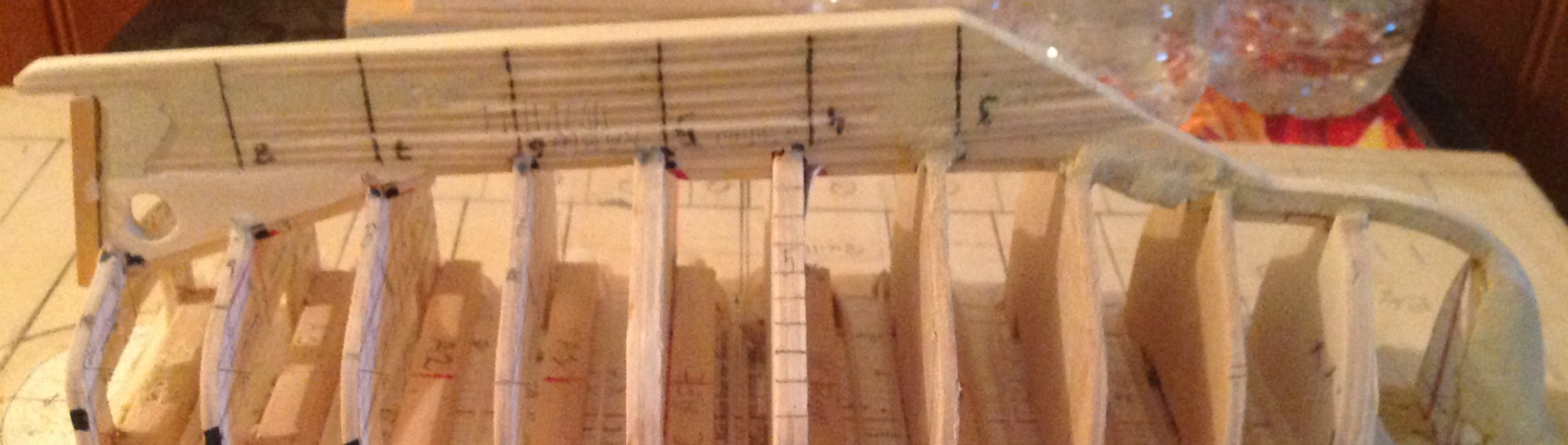
-
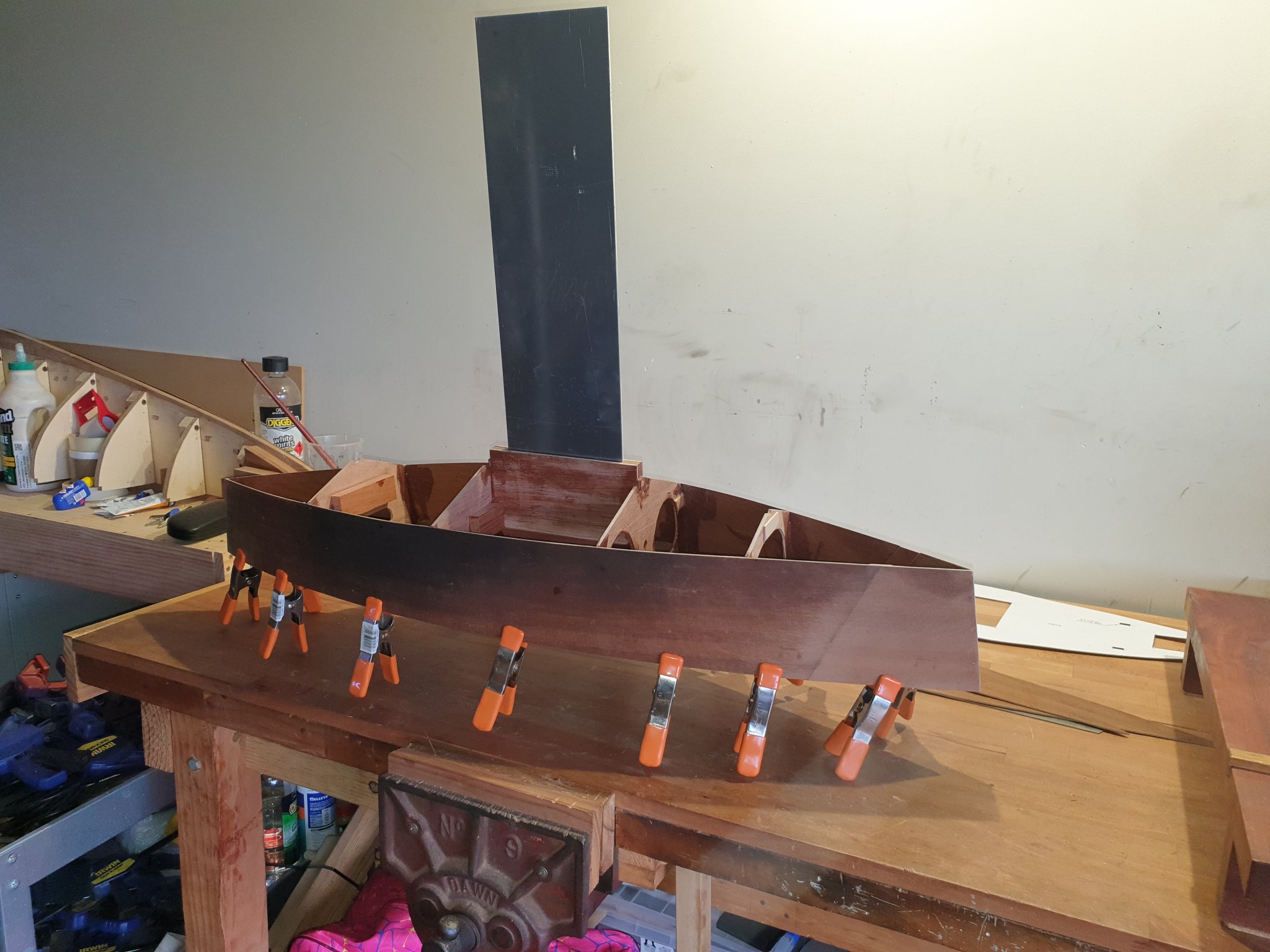
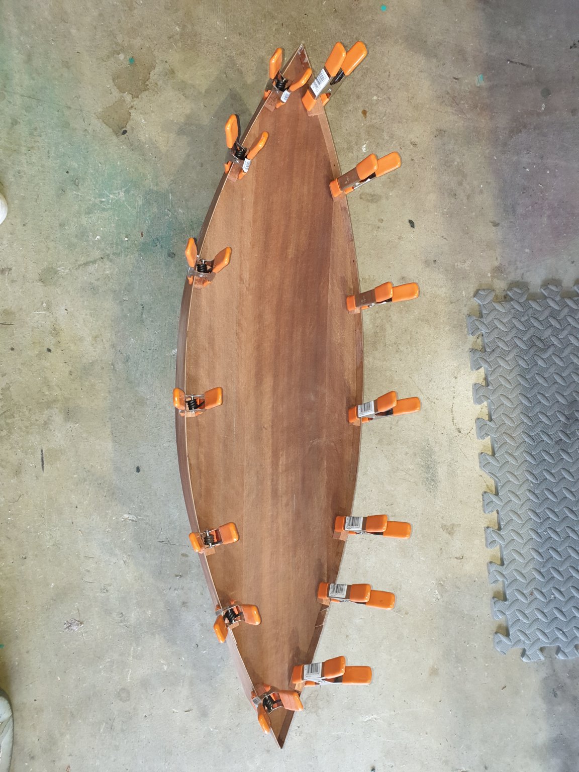
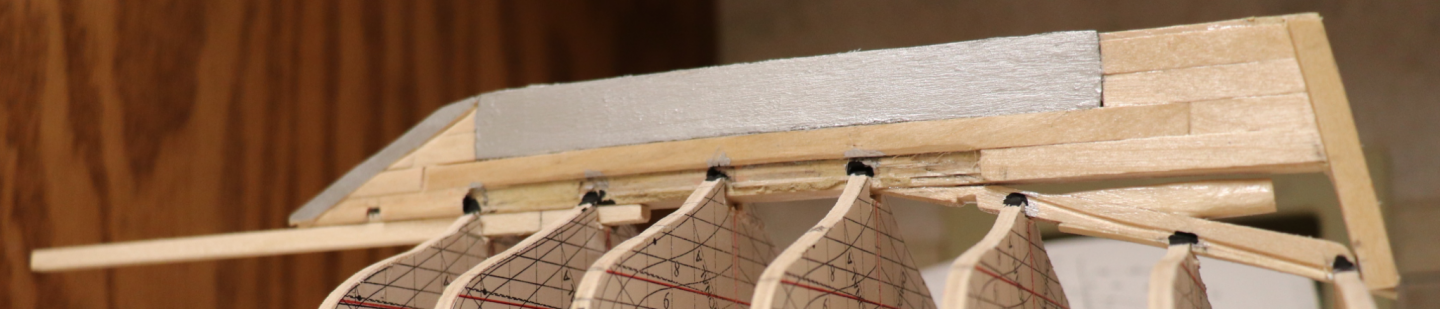
 Well, it has been awhile but the wood always waits. Good to see a lot of familiar names (and faces!). Summary: I am working to build a 1:48 scale model of the 'Friends Good Will' by access to replica build plans and lots of one on one discussions with the ship master. The Michigan Maritime Museum sails a recreation of the 'Friends Good Will' - a Bermuda Sloop that participated in the War of 1812 on the Great Lakes (both sides). My family went there one day and I was very interested in what I saw. Several inaccuracies were very apparent for the sake of safety and the ability to host guests (sails 3 times a day for 1 1/2 hours) but it felt great to see an actual wooden ship in action. At the gift shop I inquired about ship plans, hull lines, etc and was met with a blank stare. I finally was referred to the museum historian and asked about wanting to make a model of the ship. Apparently I was the first to ask such a thing so next thing I know I had full access to the build plans and unfettered access to the ship master. Things to make you go hmmmm: 1. The rigging in its short life has been drastically altered since delivery. There was no accurate documentation of the current rigging setup other than in the ship master's head. 2. The hull (especially underwater) only very crudely resembled a Bermuda Sloop. 3. How to represent the topside deck - as built or more like it would have been. The work before me was large, but I looked forward to the challenge. Join me on a journey from drafting model plans to construction (using the Harold Hahn method). -Mark
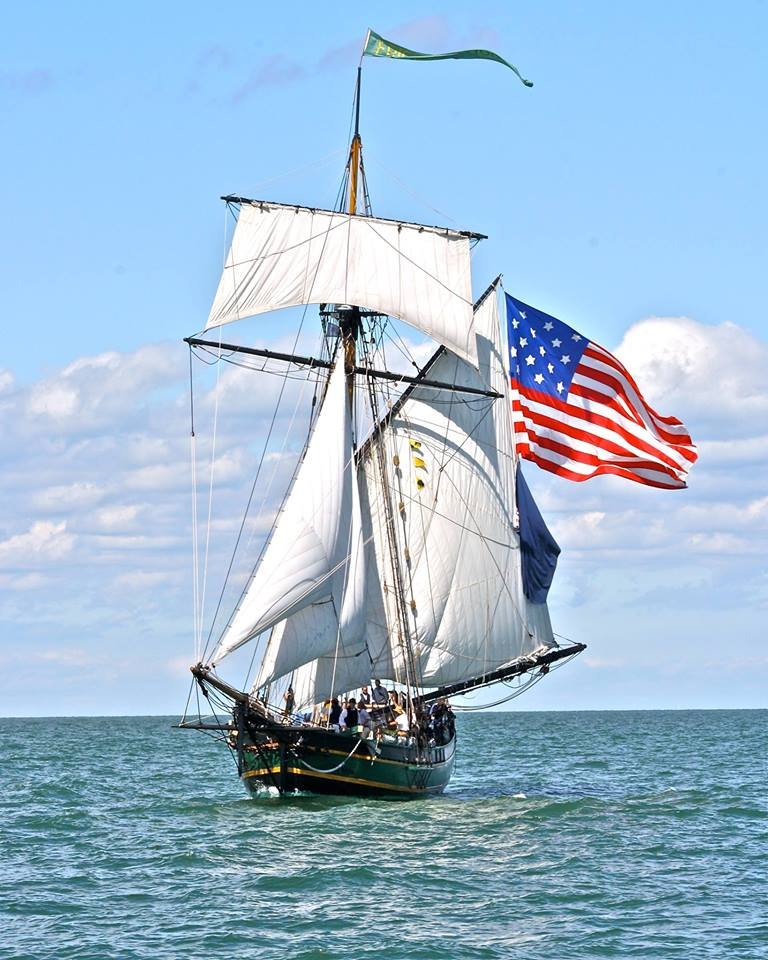
-
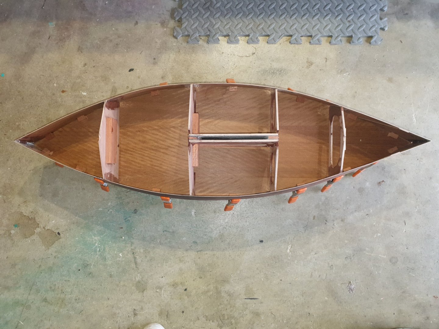
 If you woukd like to see Emma sailing then go on to you tube and Type in " Emma, rc sailing sloop by Gary Webb". Gary has quite a few vids out there now on how to do this and that with boats he has dedigned. Gary is a full scale boat builder and exceptional modeller. He models to very clear cut clean lines with practicalities coming foremost. I ordered up the plans from USA electronically so received them pdf and had them printed out to the correct size. Emma is a very simple hard chine boat and made from door skins as opposed to the really expensive 3mm birch ply from the model shops. So she is rugged but cheap to build. I cut out the four bulkhead patterns from the plan. I leave around 6mm on the perifery ( sorry my false teeth fell out saying that so I ended up spelling it wrongly). Then glued onto the ply and fretted out with my electric fret saw. The crotch of this hull is to build the fin box first and then glue it to the centre two bulkheads. The sides if the fin box were first treated with fibre glass matting for water proofing and strength. The centre two bulkheads were then glued on to it. The crotch was first C A glued to hold it together and then a fillet of 5 minute epoxy applied on every joint. Strong as an ox!. The sides of the hull had three small holes drilled biw and stern to enable the two sides to be stitched together with copper wire from an earth cable. After stitching, the sides were held apart and the crotch unit CA d in its marked position. It was then epoxy filleted at all joints. Finally the two other bulkheads were fitted in thr same fashion. The hull bottoms were then cut out and glued on using the same procedure.

-
 My next model will be the Continental Sloop Providence. I became interested in this boat after reading, “Valour Fore & Aft”, by Hope Rider. Despite being a history of the boat, the book was a great swashbuckling story. I recommend it. The boat was built by a Rhode Island merchant named John Brown several years before the American Revolution and was named the Katy. The sloop was converted to a privateer and commanded by three excellent captains, and during its voyages, achieved several ‘firsts’ for the Continental navy. The first captain was Abraham Wipple. The Katy, under the command of Captain Wipple, was the first ship to be chosen by the Continental Congress to perform naval service. It was the first colonial flagship and fired the first broadside during the Revolutionary War at sea. It also captured the first Brittish naval ship. In late 1775 the sloop’s name was changed to the Providence. In 1776, command of the sloop Providence was given to the newly promoted John Paul Jones. (Later Captain Wipple was given command of a new continental frigate also called the Providence.) Of the three captains, John Paul Jones succeeded in taking the most Brittish prizes. In 1777, command was given to John Peck Rathbun who was one of the sloop’s Lieutenants. Under the command of John Rathbun, Providence was the first Colonial ship to land marines on a foreign soil. Also, she was the first to fly the Continental colors over foreign territory. She captured Fort Nassau and held the town until valuable military supplies were removed and several Brittish ships taken as prizes. The Providence met its end as part of the disasterous Penobscot Expedition in 1779. She was forced up the Penobscot River in Maine and burnt to prevent its capture by the Brittish.
- 238 replies
-
- 8
-
-
- providence
- sloop
- (and 1 more)
-
I hope I am in the right department here. If I am moved by administration please advise me and my apologies in advance. I have dabbled with SIB for some time. I make one every ten years on average. This is supposed to be HMS Beagle. I do not work from drawings. ( should do ) All is eyesighted and let's say...artists impression? I have seen some of the most exquisite models built by guys on this forum which leave me very humbled. They are just brilliant with all their tiny detail. I love ships but am a bit of a bluffer. I put in what I think looks good and ignore scale as it is too much for me. It is supposed to carry seven boats I read. This, on this scale will be too overpowered. I have tried my best. I am a non nautical but love what I see in ships . I have the boat hanging over the stern on Daviits which should be a give away for HMS Beagle. Plus all the other boats on board for the expedition. When I see what some modellers have achieved I should be ashamed as I have not applied myself fully to it. Anyway, here are my results so far. The main thing here is.....FUN! and I get plenty of it. Your ships though my brothers are an inspiration to me. We cannot hope to build anything without this. I have an attraction to Dimple bottles of the smaller variety. They have their own stand. Trouble is I get quite Ill for five days having downed a bottle in one evening! Maybe I WAS a sailor in my past life? Ha ha. I do know though that us modellers have a vivid imagination of the past and that's why we do what we do. Here's the pics. " Weigh Anchor and set sail me boys" Or have I got it the wrong way around? Said I was bluffer!!! In hindsight...I Christen this ship..." HMS Bluffer ". Pete
-
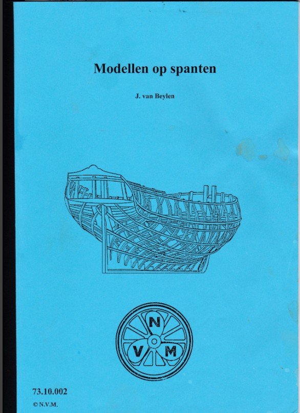
 Part 1: Introduction My fishing smack cross section is finished; a new project is already sprouting. But first my workshop is urgently in need of a deep cleaning and there are also a lot of jobs waiting for me in and around the house of which the priority must be upgraded if I want to preserve the peace in the household. So the start of my new project will have to wait. That does not mean that I will go off-line for a while. While making the fishing smack cross section, I was simultaneously working at another POF model. I didn't want to keep up two logs at the same time, but now the pictures are sorted and the model is well advanced, enough to keep the log running while I am busy with other things. I can continue giving weekly updates retroactively at least until I am ready again to start a new project. My previous building projects were working boats (Ostend shrimper and fishing smack) and a warship (HMS Triton cross section). Now I want to build a pleasure boat. I found my boat in an small handout for making plank-on-frame models that I bought some years ago from 'Nederlandse Vereniging voor Modelbouwers' (http://www.modelbouwers.nl/ ). The handout is an assembly of articles which appeared round 1950 in the Dutch magazine 'De Modelbouwer'. They are written by Jules Van Beylen, former conservator of the Belgian National Maritime Museum in Antwerp. In the handout Jules Van Beylen explains how to build plank on frame models on the basis of four small ship models varying from basic to moderate level. The second model of the handout will be the subject of my project. It is a small gaff sailing sloop with a retractable center board. It is an imaginary boat, a design of Jules Van Beylen just for modeling. I doubt that real examples of it ever have been built. One of my previous builds, a coastal fishing sloop was a simple boat, but it took me almost three years to build it (and it is not yet complete now). This is a much more elementary model, so it will be finished somewhat faster. The plans include two sheet: a general construction plan and a rigging plan and are not included in the handout, they have to be bought separately at the 'Nederlandse Vereniging voor Modelbouwers' (http://www.modelbouwers.nl/). They are laying already some years in a drawer waiting to be used. The model will be built at scale 1/10. It is a 7.50 m long hull, so the length of the model will be 75 cm.


- 209 replies
-
- 10
-
-
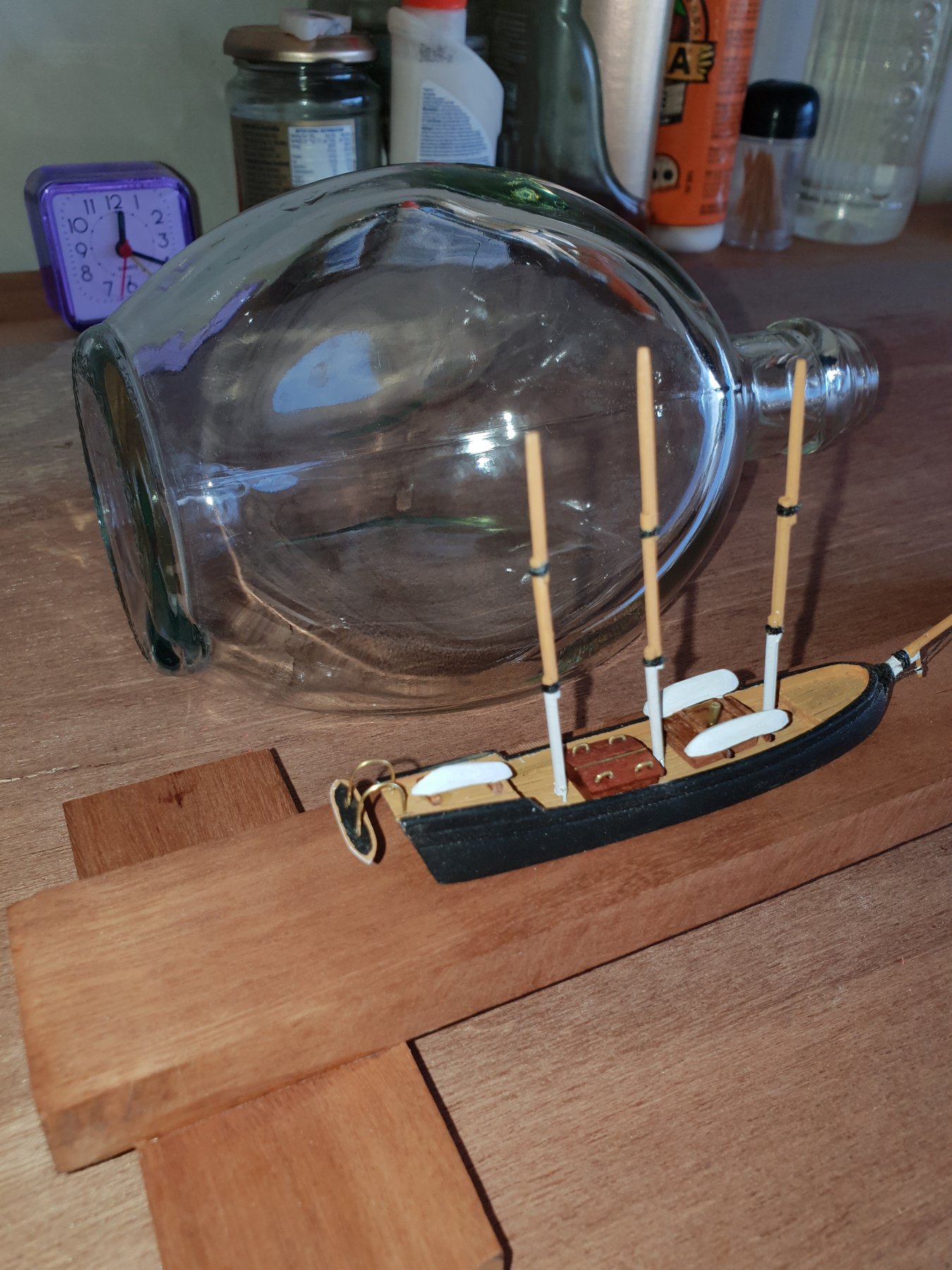
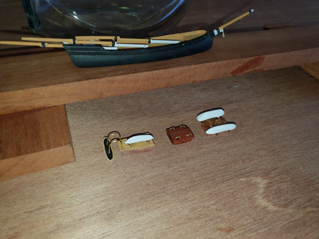
 I started this build on www.bottledshipbuilder.com. It fits with the mission of that site but the idea of this build is one I've had for a long time and it began with MSW members in mind so I thought I'd bring it over. To give a little history and the idea of what this build is, it started with a pet peave of mine. Those that have seen me on the forum have probably seen that I have been critical of ship in bottle kit's out there. I have seen a lot of MSW members and members of my local club take interest in ships in bottles then try a kit and end up never wanting to build ships in bottles again. As many of you also know ships in bottles is something I'm passionate about. Probably overly so. I'm not sure I can explain that passion. For me it's something magical. I get a ship into a bottle and I stand back and I'm still amazed that I was able to do it. I know the process but it still amazes me. The other part of that passion is those that helped me get to where I'm at. I feel like I was very lucky I got into ship in bottle building when I did. I found these small groups with cheerful members willing to share their ideas and I learned very quickly. I owe a lot to the members of the Ship in Bottle Association of America. Unfortunately SIBAA closed a couple years ago and www.bottledshipbuilder.com and the Facebook ship in bottle builder group what's left of the organization. Much like ship modeling in general ship in bottle building is a dying art. In an effort to keep it alive and pass on the knowledge that was given to me I like to share ship in bottle building methods and knowledge. So it bugs me a bit when a company puts out a model that is overly difficult and turns people off to building ships in bottles. In my personal opinion there is currently no kit on the market that gives what members of MSW would look for in a ship in bottle kit. The closest one is Amati's but I think they made their ship to tight of a fit which has given a lot of beginning ship in bottle builders trouble. Every other kit is to kiddish to be taken seriously by members of MSW. I had thought for a long time about making my own kit. I've explored that process and found a lot of complications to it. Besides that for a patience bottle builder I'm not very patient. I have a hard time measuring and writing all the details so I decided on a different approach. In an effort to give this information as freely as it was given to me I am posting a how to build log. It will detail all the steps for a simple ship in bottle build. The idea being if I were to make a ship in bottle kit for beginners this is what it would look like. Since I'm not detailing every measurement this also acts as a guide to scratch building. If you can build this ship you can use the same techniques to build others. Also this gives builders the ability to size it up or down as needed. I want this to be a great starting place for those want to try ship in bottle building and I'm hopeful I can present it in such a way that will share the magic of it and have builders wanting to try more.
 -
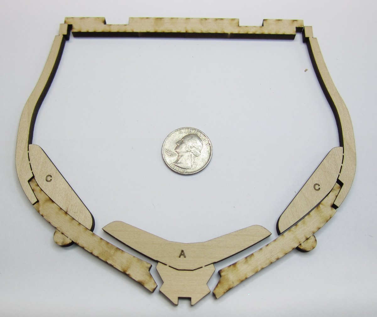
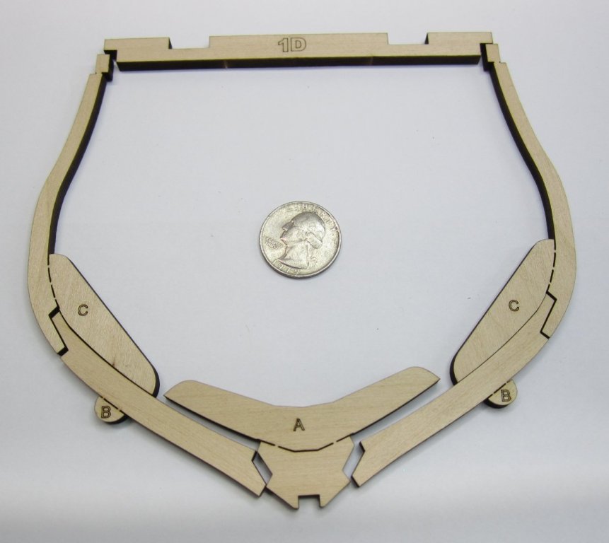
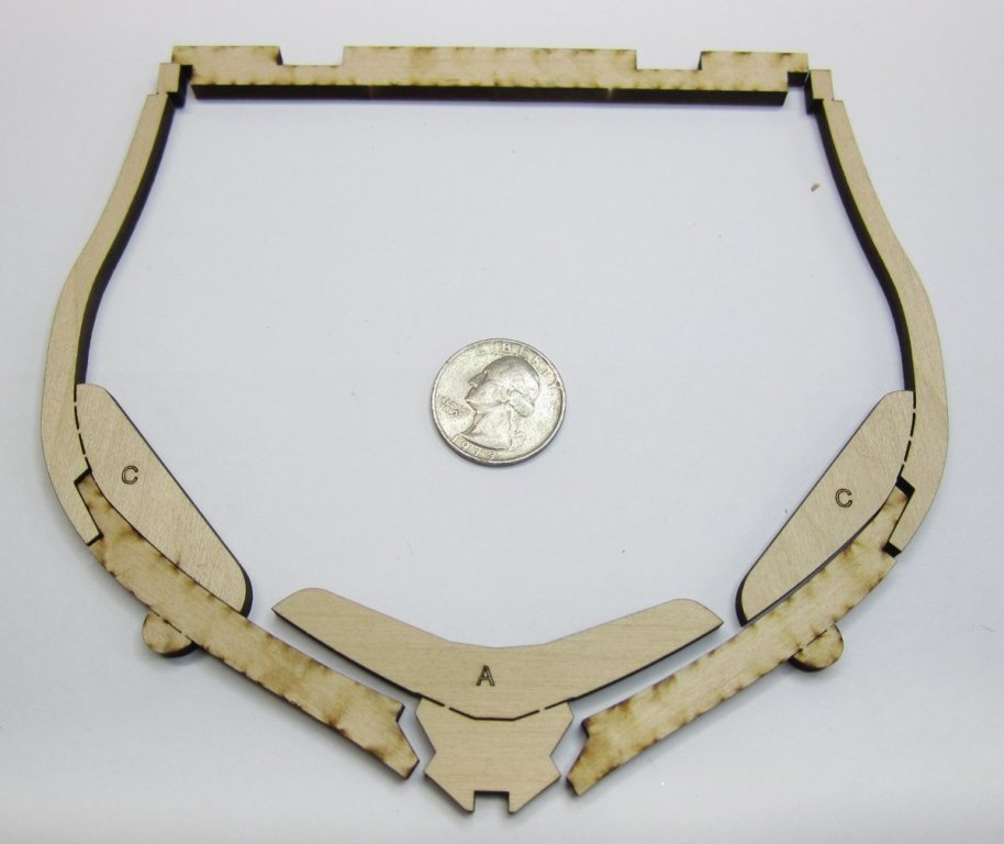
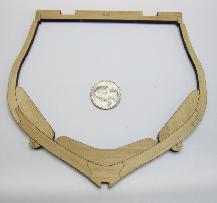
 I have started the cross section model...mostly drafting. But I figured I would start a log. I am waiting on arrival of a variety of machine screws and nuts to finish drafting the keel parts. They will be set up in the usual fashion you folks have seen but I will post that once its ready. Here is the overall plan I am working from. Hopefully it will look like this once done...planked on one side and open framed on the other. I have started drafting the frames. There will be some bent frames with curved top timbers but this is just a plain straight one. Here are the laser cut pieces.....but you will not build the frame with the parts laid out like this. Because the laser cuts on an angle, it is best to strategically flip certain parts to get the tightest fit possible. You wont get one side with a large gap which is typical. Therefore no sanding of the char is needed ...nor should you attempt to sand the char from the edges of all joints that fit together. They will fit perfectly as is. The only drawback is that you will see the seam which in some instances was not the case as they werent tarred. But thats OK.... So I flipped them as I show in the photo below....flip parts "C" and "D" for the best fit possible. Note the dirty side on the flipped parts. There is no need to build each frame on top of a plan trying to get the frame to come out the correct shape. I have created some tabbed guides which make it very easy. I built five of these frames and they all came out the same...Each one took just a few minutes. I used titebond on the seams. Just take care not to glue the guides to the frame. See below. All glued up. Then the guide tabs are cut free leaving the frame strong and ready for sanding. I sanded every edge to remove the char except for the notch in the bottom chock which stays unsanded. It needs to be a perfect press fit into notches I created in the rising wood...which I will show later. But the finished frame all sanded up up looks like the one below. The top cross bar is added for strength and also to help register all of the frames once they are glued onto the keel. That is what those two notches on the cross bar are for. After I draft more frames it will make more sense. Chuck
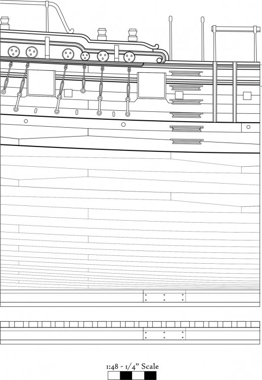

- 130 replies
-
- 48
-
-
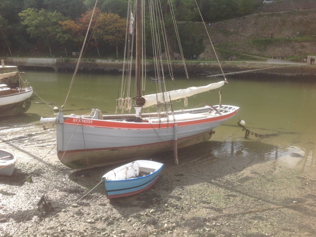
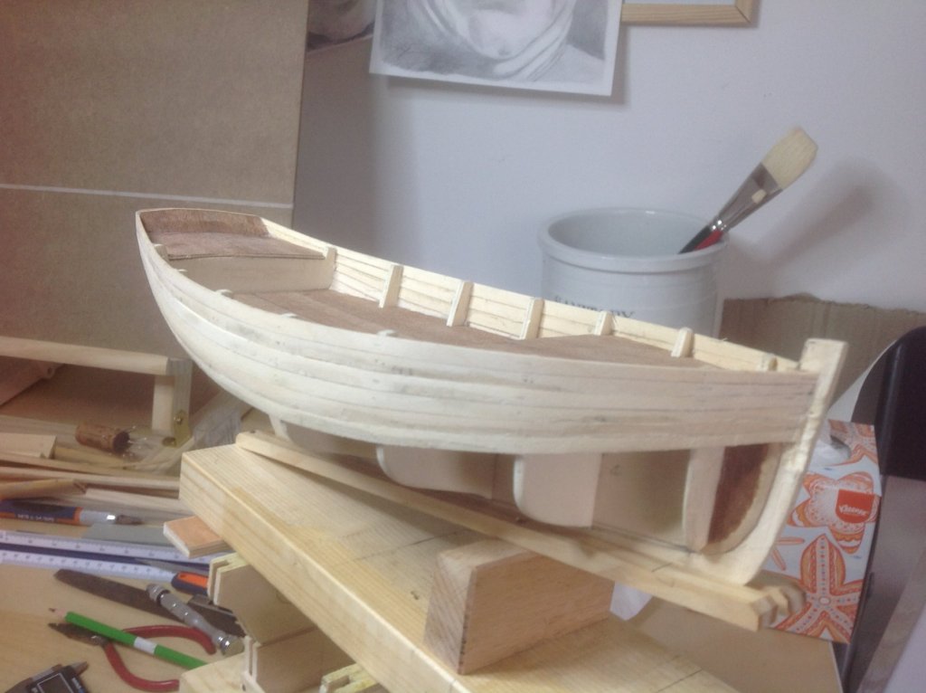
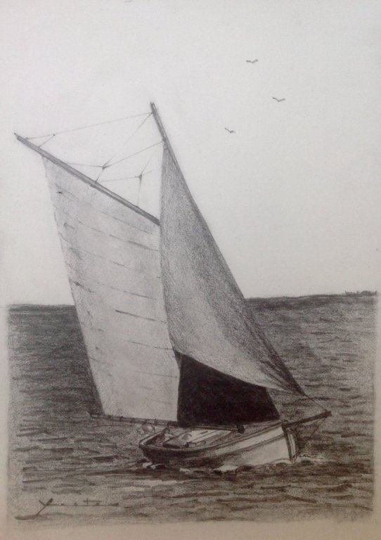
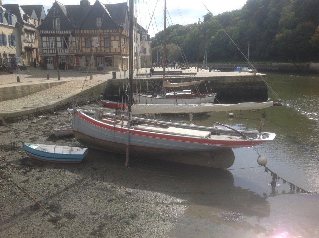
Currently interested in the evolution of the working sloops of Brittany, and finding relevant contemporary drawings.
-
Hi, My name is Bill. I live in Brittany in France. I am a new member, currently building the Corel Sloop (or Sloup), and researching the history of these work- boats on the south and north coasts of Brittany. They have beautiful lines. I am also interested in developing CNC techniques to improve fairing of frames and planking in a general way for wooden hulls. Happy to hear from anyone with interests in these areas.

-
 Hi all I have not been around for a while busy with life I guess. I have just finished a RC sailing boat using a fiberglass hull of a Muscongus Bay Sloop made by a guy I met down at the local lake one Sunday sailing a 1 MT class yacht. We got to talking and he offered to sell me the hull for around $50 plus a handful of wood and lead for the keel ballast. So I set about building her using a Gaff rig and twin jibs, I already had the rc gear left over from my model aircraft days although its a 8 ch set Overkill for a 2 ch yaucht. Took me a few months to get her finished as I had never built a yaucht before lucky for me my dad is a shipwright and a accomplished sailor from way back. had to build everything from scratch including the sails from witch I made out of cotton poplin. made a fiew stuff ups for instance I made the boom half the length it should have been and had to make a second set of jibs as the first set were compleat crap I still have to re make the mainsail as the luff has a sag in it. anyways her are some picks of her My wife asked me to name her Wiggles after our red kelpie who loved walking around the lake sadly se passed at the age of 18.
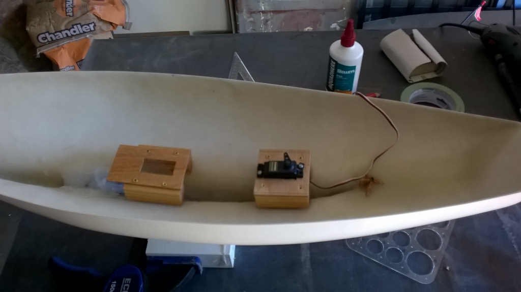
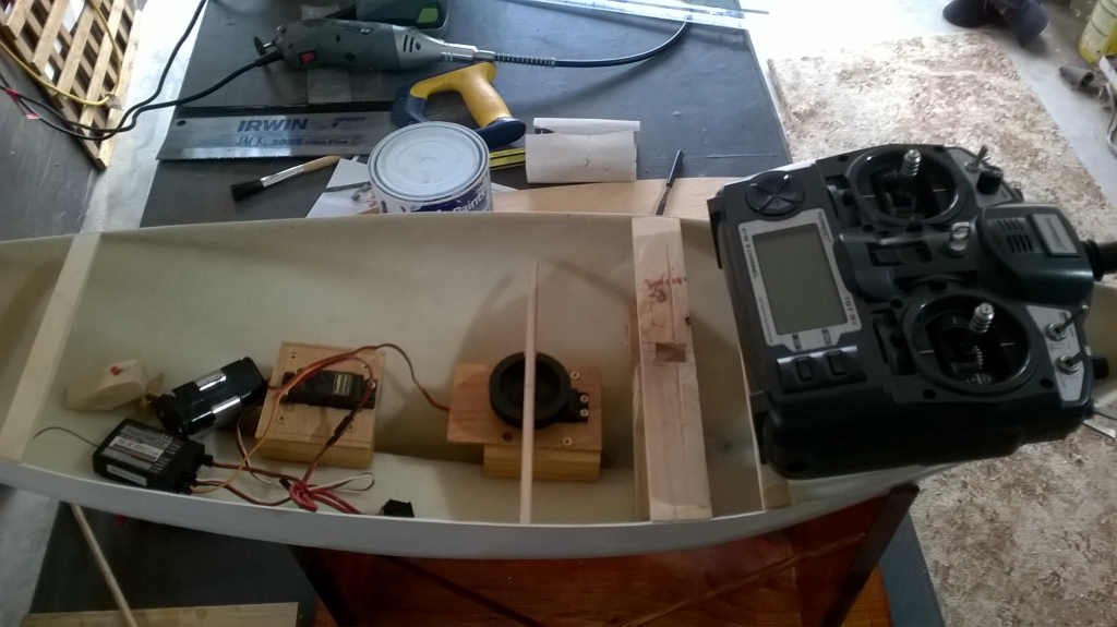
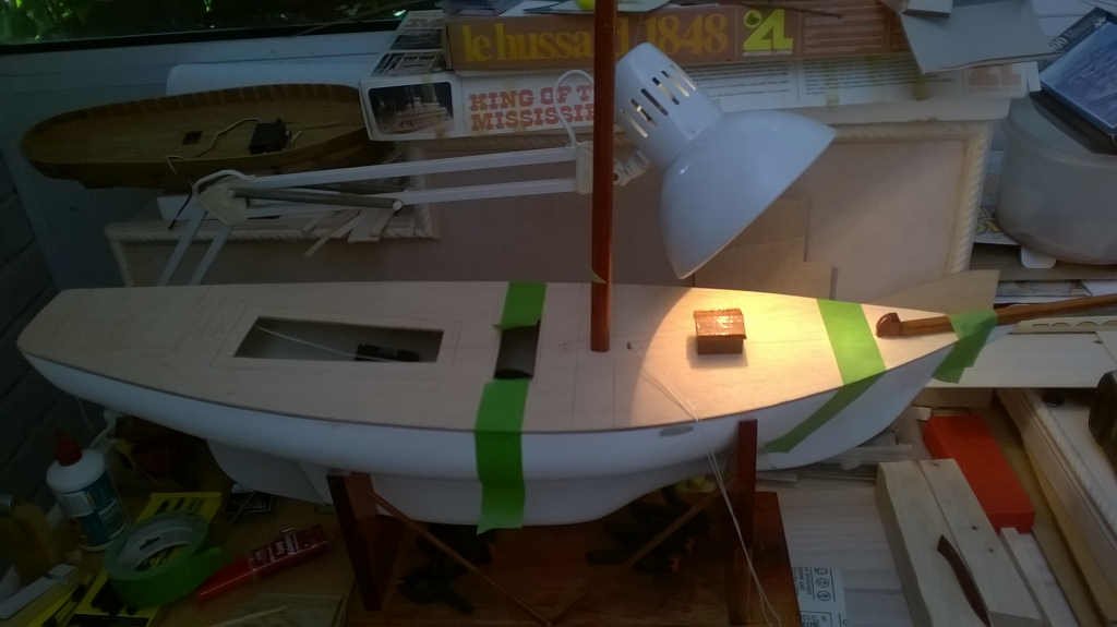
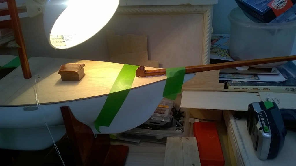
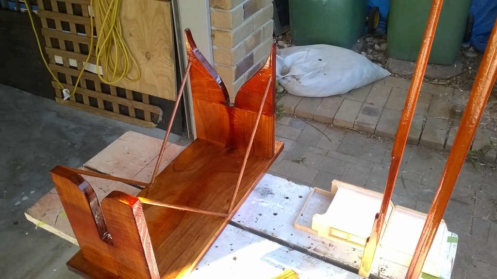
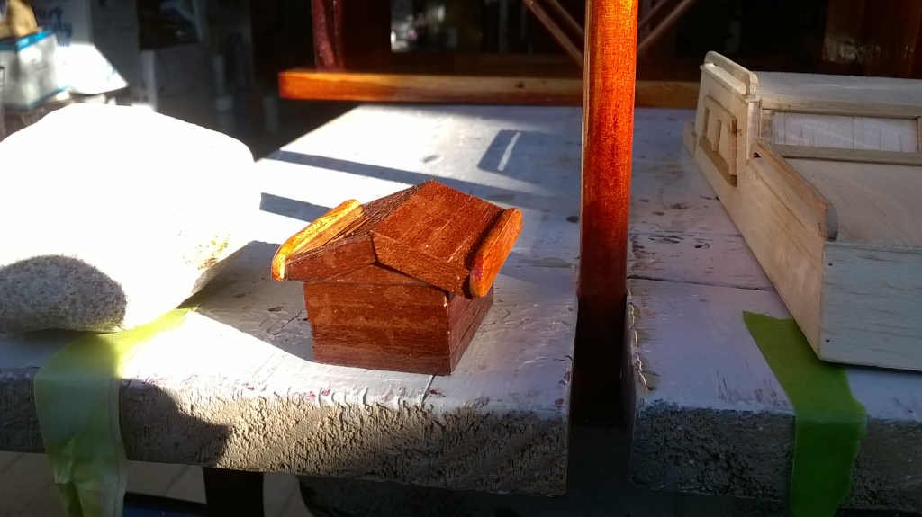

- 5 replies
-
- 2
-
-
- sloop
- muscongus bay
- (and 1 more)
-
 Hi all Wondering if anyone may have a copy of " BUILDING THE SWAN CLASS SLOOP PEGASUS 1777. Volume III by Greg Herbert" at a reasonable price. I am after working on the HMS Pegasus model and want to use the book as a means to get information and ideas. The book is available but at a rather hefty peice so I thought i'd see here first. Many thanks Terry
 -
 Hi friends, I would like to begin this WIP thanking DocBlake for giving me the references of Bob Hunt, and thus succeed in obtaining the construction plans. Thank's Bob for your patience and shipment assistence. I want to build this AVS with pear wood, obtaining the parts to boards from a tree that had cut long time ago. Soon I'll post pictures with the initial stages of construction. Again, i wish to excuse for my English. Regards Valter
 -
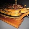 The HMS Beagle served as Charles Darwin's floating laboratory on his historic voyage to the Galapagos Islands. Drawings: I traced the drawings I needed to generate the modeling plans from the book Anatomy of the ship HMS Beagle using AutoCAD. The Keel Assemble The Keel Assembly is 24 ½” long x ¼” thick European Beachwood. Since this is going to be a Navy Board type model I simplified the keel and framing. This set of photos shows the keel assembly and the first two frames. All the frames are double and consist of ten individual sections each.
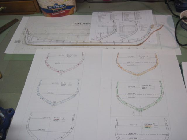
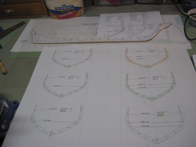
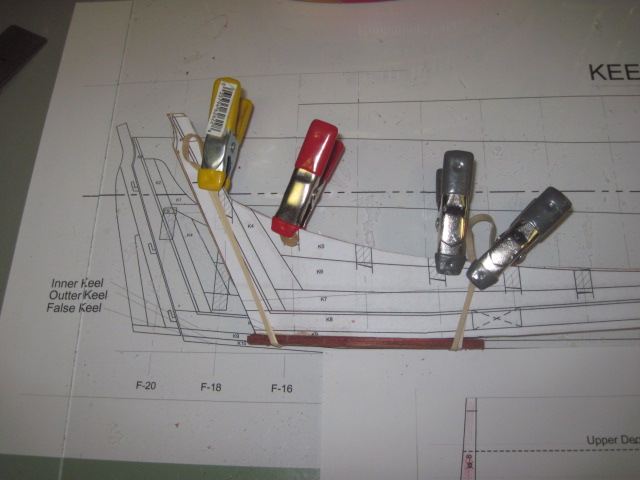
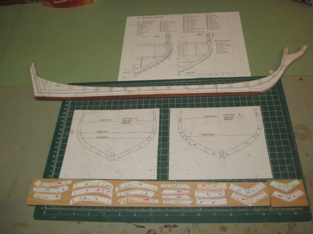
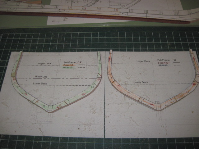
-
 Hi folks, the new project. I am not the sole builder of this model which is a club project for the Ship Modelling Society of Victoria. I am coordinating the build, doing the research, drawing the plans and assisting in the build process. I am providing this log as she is an interesting ship and I thought members may be interested. While designed as a warship along the lines of the contemporary Arrow and Vigilant Classes of Gun Dispatch vessels, she was operated in various roles, with only a very short period of active duty as a commissioned ship during the Maori Wars in New Zealand. Her Majesty’s Colonial Screw Sloop (HMCSS) Victoria was built for the defence of the Colony of Victoria during the gold rush era. The above image is a copy of a purchased image from The Illustrated London News which shows her during her Builders Trials. Additionally, as much of the hull construction has already been completed, I will provide a summary of this part of the build only.
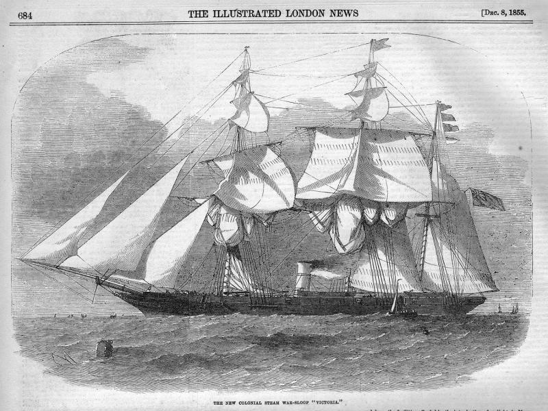
- 973 replies
-
- 13
-
-
- screw
- gun dispatch vessel
- (and 5 more)
-
 I enlarged and printed the pattern sheet today.....have a good idea where my tracing vellum is along with my drawing tools. This is exciting. ....this is going to be a REALLY big ship. Onward, Pamela