
.JPG.ca33079f5815b861e67b9c2cccd37982.JPG)

Blue Ensign
-
Posts
4,572 -
Joined
-
Last visited
Content Type
Profiles
Forums
Gallery
Events
Everything posted by Blue Ensign
-
 Ha, Ha, thank you Ron, Unlike Sisyphean I at least have the option to stop, and I may well take a break once I have completed the ‘official’ allocation. When my resolve starts to flag with the seemingly endless task of planking these little beggars, I think of James, tasked to complete whatever arrives from the dark Forest of Dean, and to a standard demanded by the Gods. Any failure means the task is repeated, any success and the reward is more of the same. I then feel much better.😉 B.E.
- 857 replies
-
- 7
-

-

-
- Sphinx
- Vanguard Models
- (and 1 more)
-
Looks like a great day out for ship modellers, Ron, love your Swan in her seascape setting. B.E.
- 542 replies
-
- 4
-
-
- Sphinx
- Vanguard Models
- (and 3 more)
-
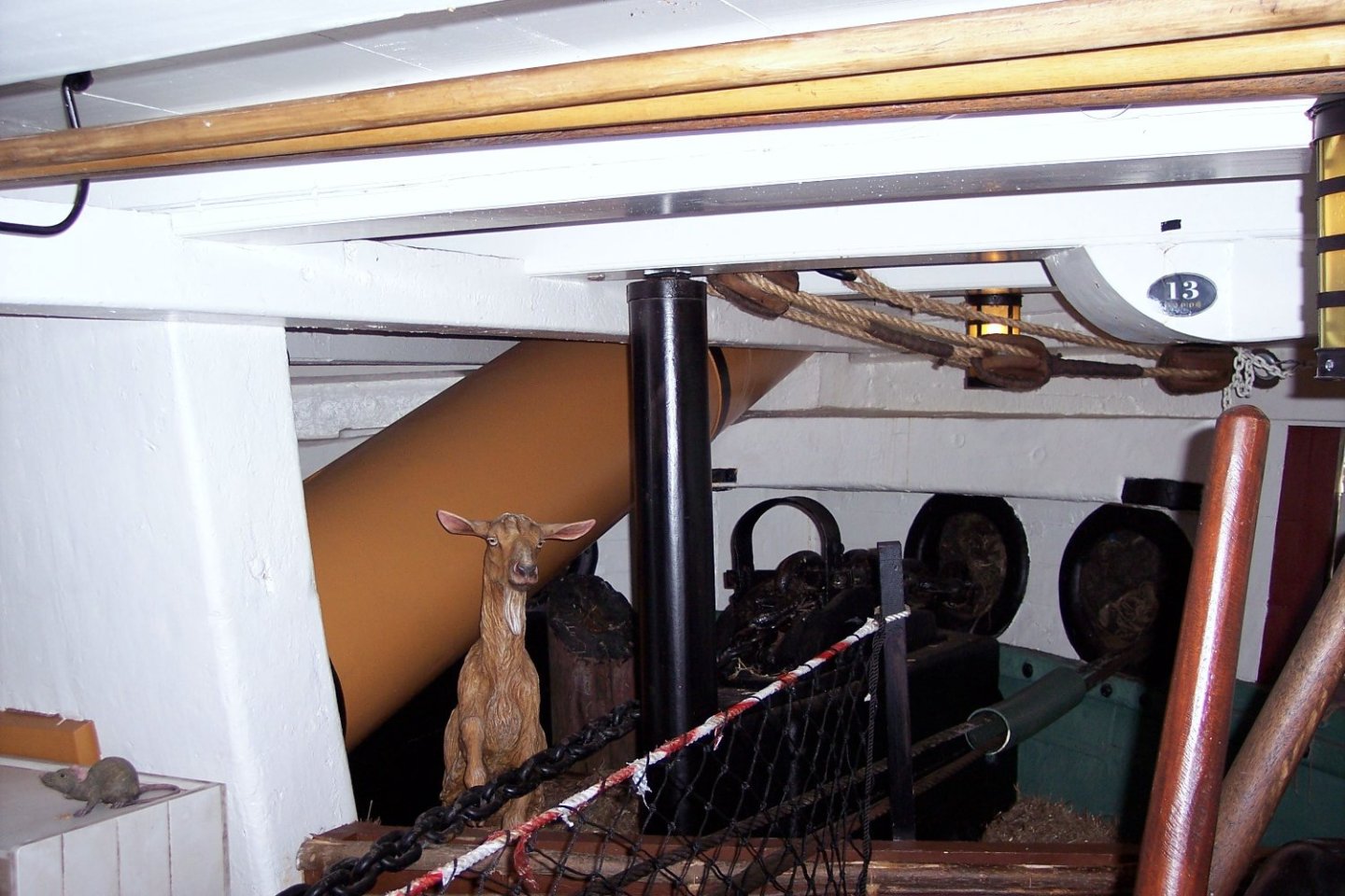
If you're going for a cook, don't forget a goat for the manger. Oh and a rat, what galley would be authentic without one. B.E.
-
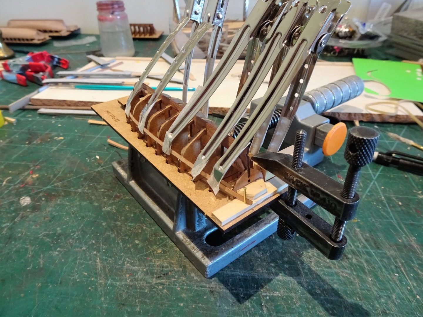
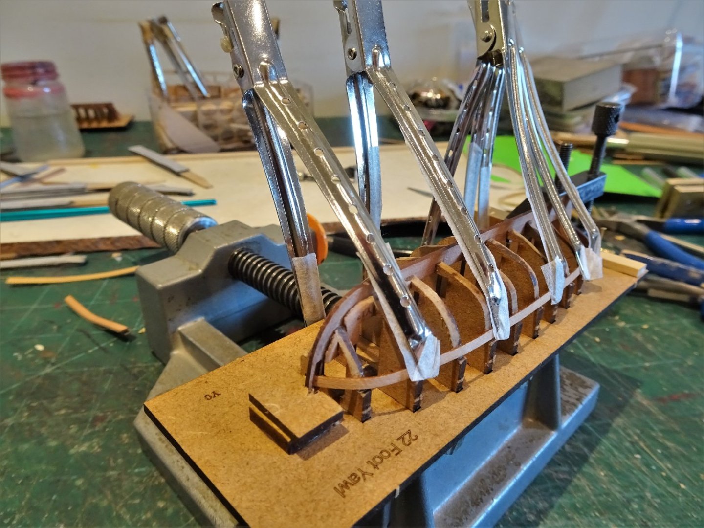
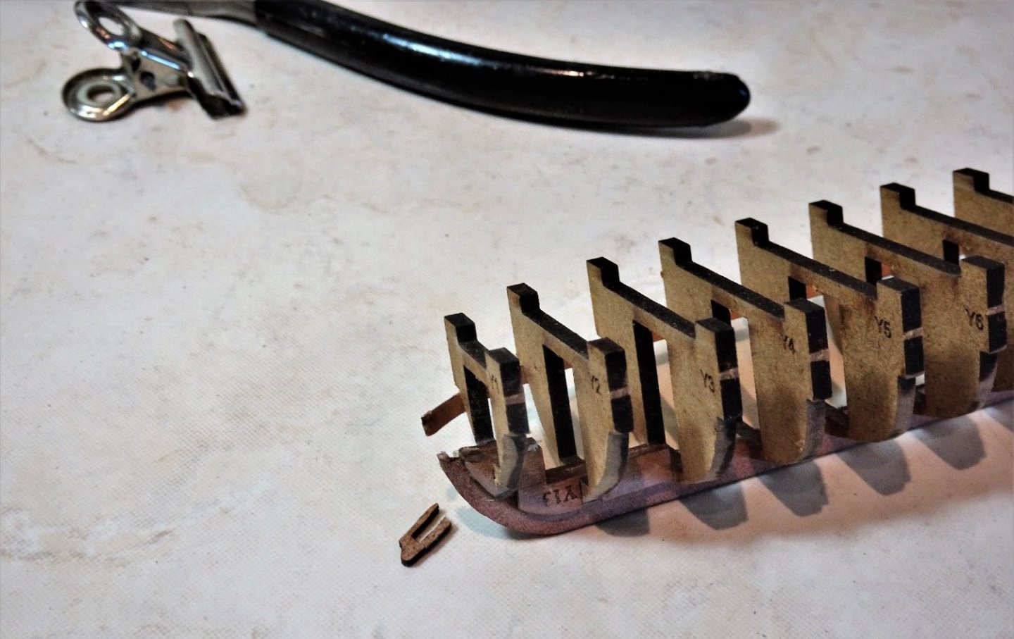
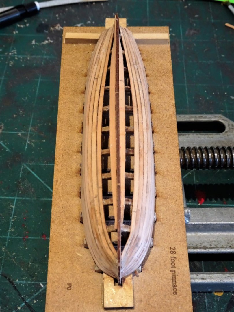
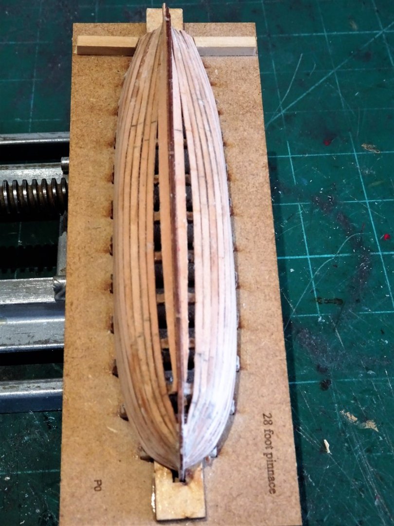
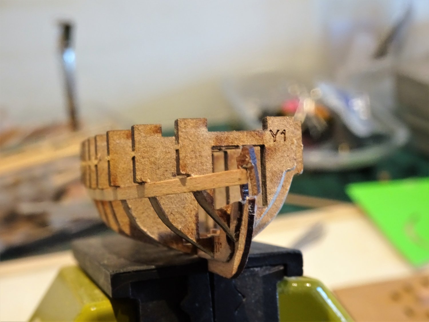
Post One Hundred and Fifty-one The Yawl saga continues. With a replacement stem part made from some 1mm fret, (vertical grain pattern essential), planking recommences. For anyone interested the ‘how to’ of this repair it can be found in the log details of my first Yawl build. 18th c Ships boats by Blue Ensign – FINISHED - Vanguard Models -1:64 - - Kit build logs for subjects built from 1751 - 1800 - Model Ship World™ 7848(2) I’m not sure what could be done do to strengthen this weak point, reduce the size of the rabbet a little, my replacement rabbet was slightly narrower. Perhaps increase the aft side of the stem with a slave tab that could later be removed once the planking secures the stem. I don’t find it that difficult to make a replacement stem, but beginners may find it more daunting. 7850(2) With the first three strakes fitted the stem is now stable. On with the show. B.E. 08/08/2022
.thumb.JPG.37a2c03e0fd9b2f8a39455e1ba964572.JPG)
.thumb.JPG.30952a8cca8ba0e42ad60246c3a9adaf.JPG)
- 857 replies
-
- 22
-
-
- Sphinx
- Vanguard Models
- (and 1 more)
-
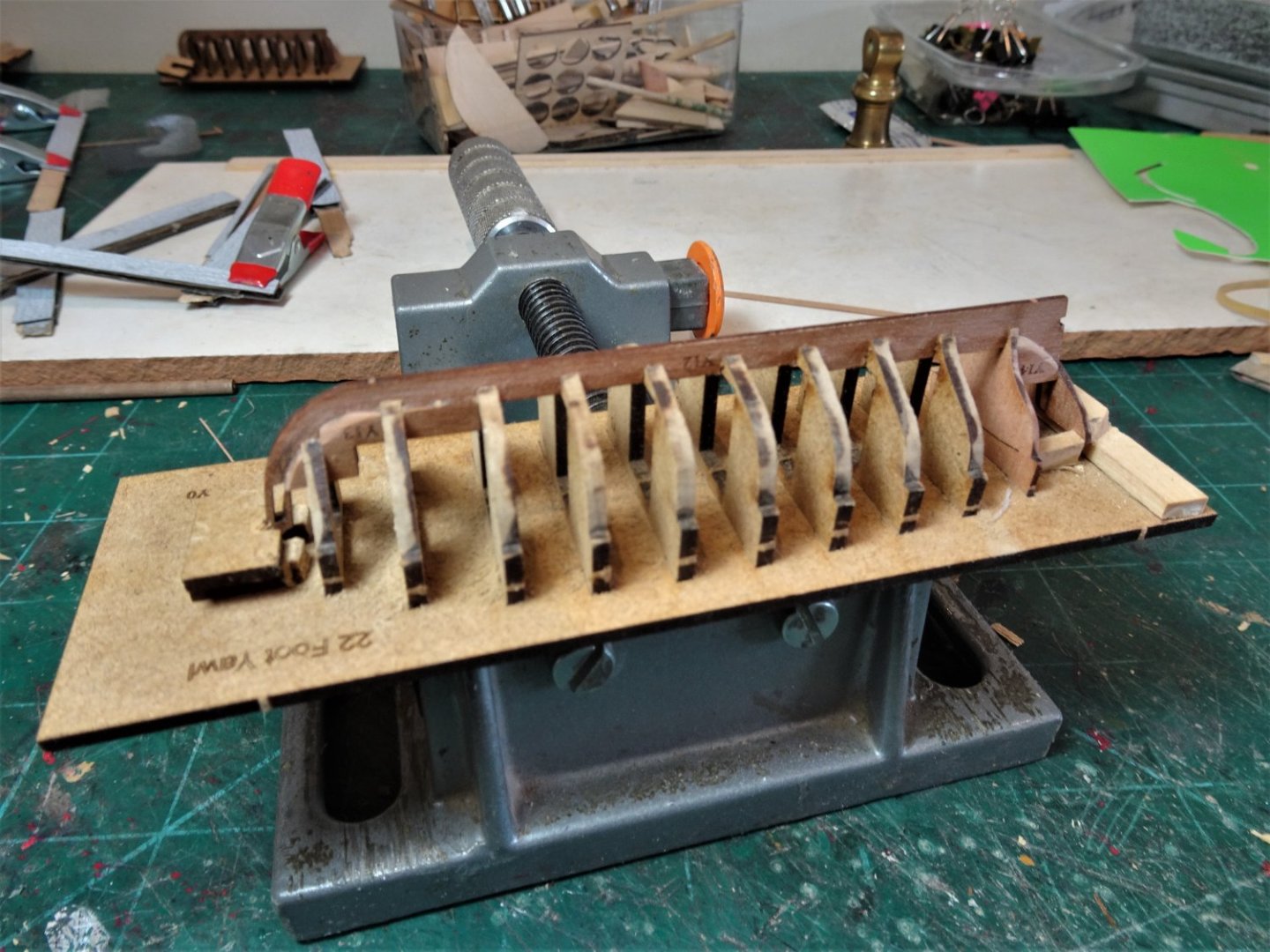
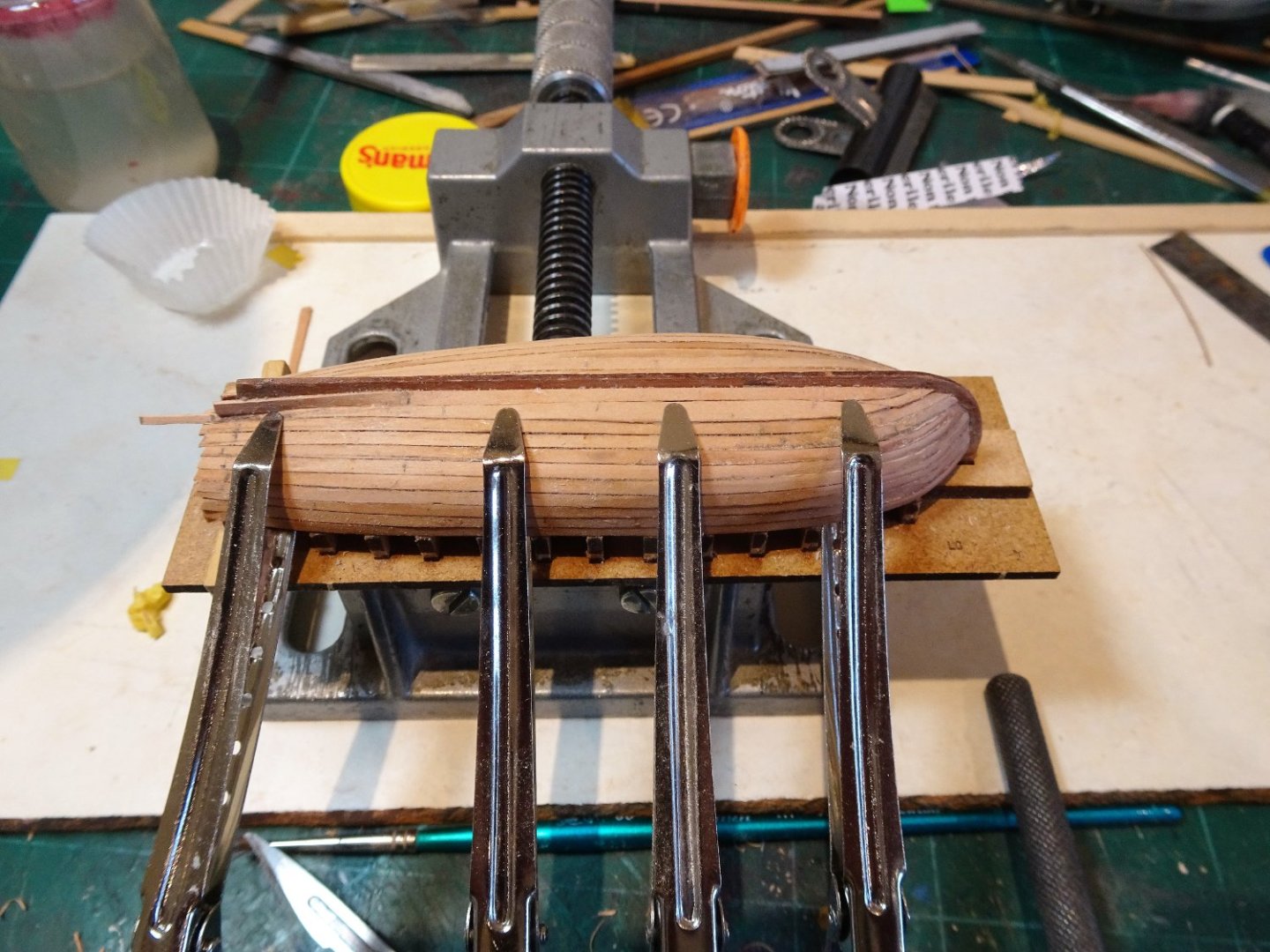
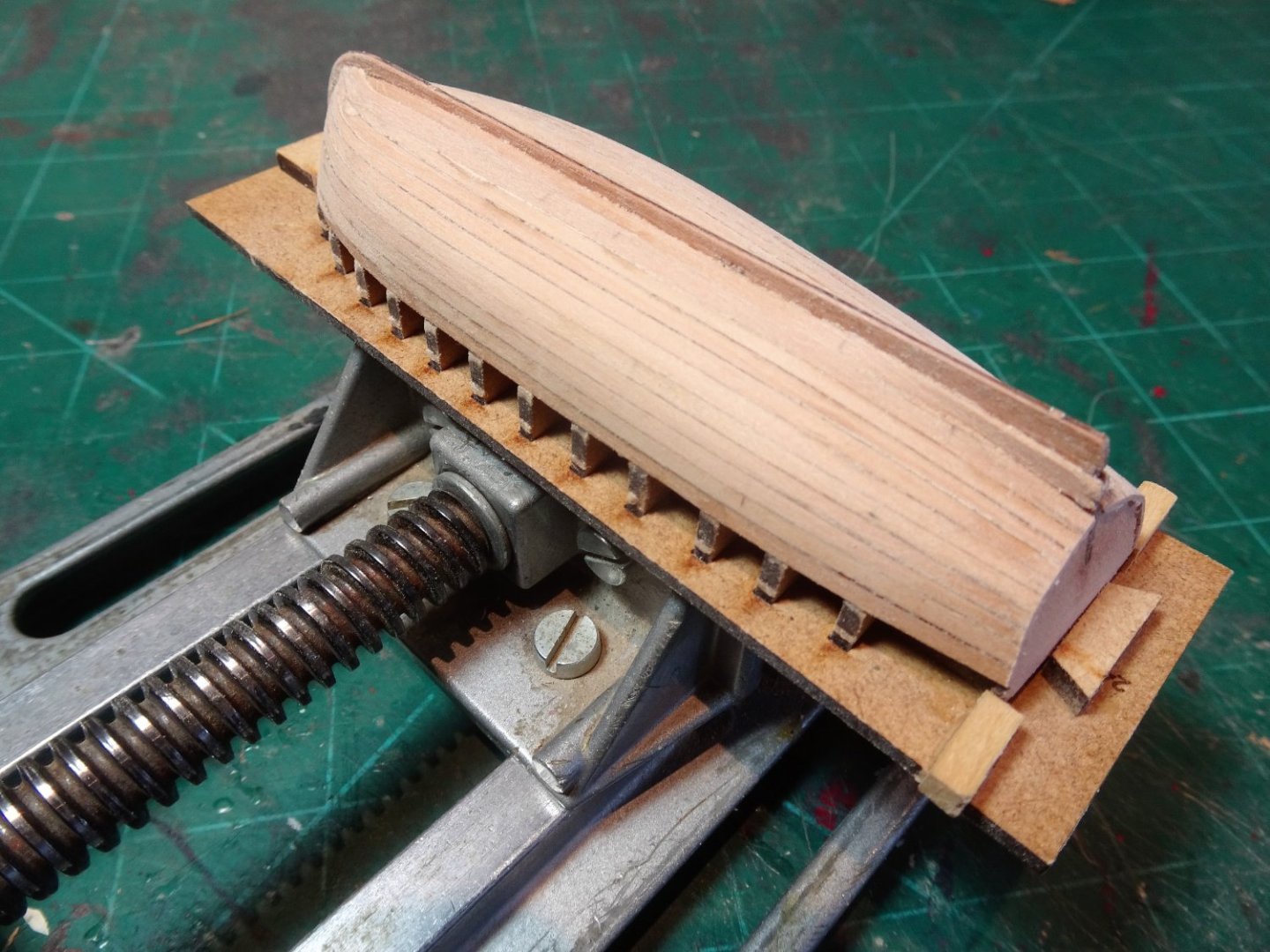
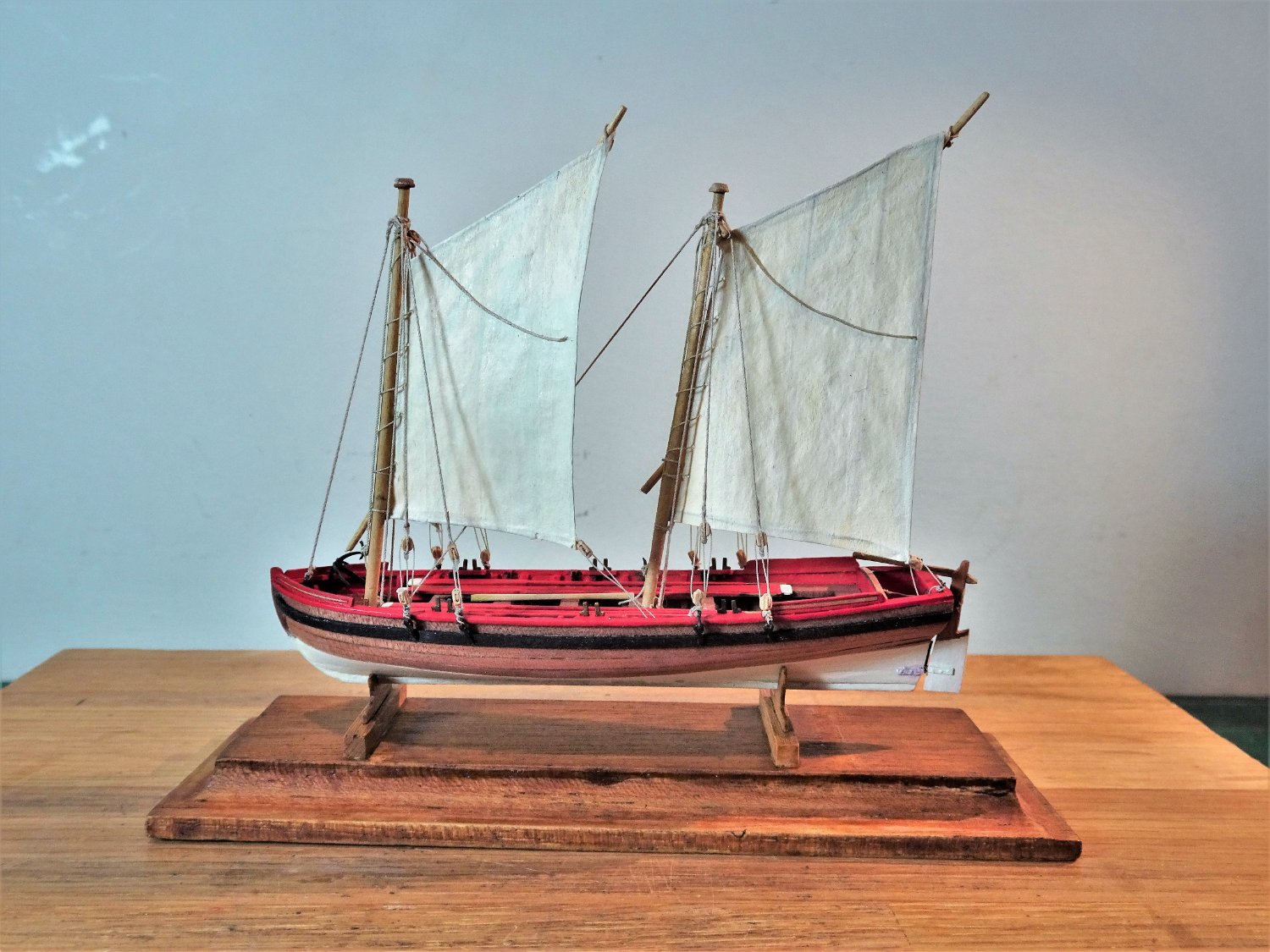
Post One Hundred and Fifty Building the Yawl. Having built the Yawl before I am curious how this second bite of the cherry will turn out. 0627 I was quite pleased with the result of my first effort which I also rigged and added sails. Two issues affected my first build, the delicate stem snapped, as did the stern transom very early in the build which necessitated some scratch replacement work. 7829 I have taken precautions this time around to hopefully avoid that situation. Support pieces have been added to the hull constructions of all the boats. 7831 Note that a temporary brace is used to hold the transom in place opposite the first strake. The pressure of gluing against the transom can easily push this delicate area out of true, or worse. 7833 The first strake is fitted, using heat only to retain the bow curve, so far so good. 7835 ....................... and it was all going so well! 7837 Despite my best efforts to protect the bow stem, it again detached at the very same point on as my first build of the Yawl. I know from previous experience that glue won’t hold it against the lateral pressure of fitting the bow planks. This is a weakness in the design of the yawl, a combination of lateral grain coupled with the very fine stem pieces created by the rabbet, almost guarantee a fail, obviously in my case. Feeling somewhat miffed, it’s back to the drawing board to scratch a new stem. B.E. 07/08/2022


- 857 replies
-
- 16
-
-

-

-
- Sphinx
- Vanguard Models
- (and 1 more)
-
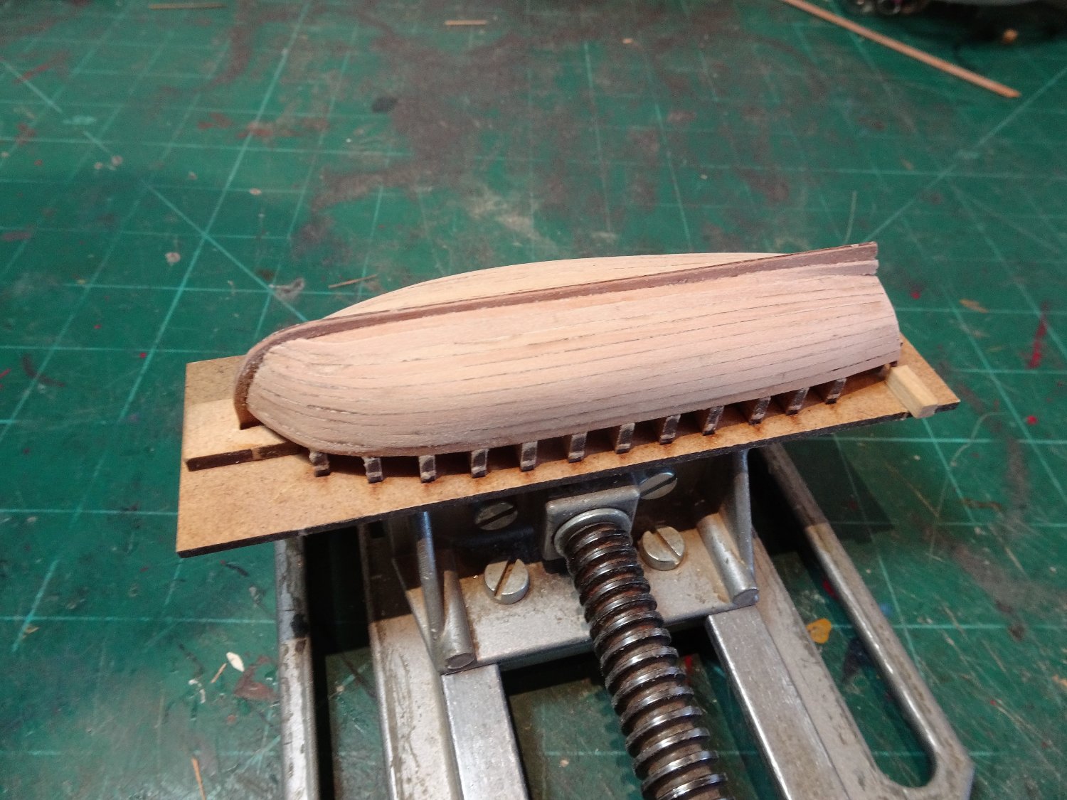
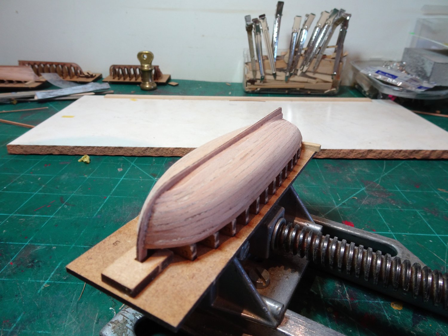
Post One Hundred and Forty-nine Building the Launch. Another four days and another hull planked. The planking method described in the blurb is simplified with the aim of getting a smooth surface that will ultimately be painted, not a bad approach. 7804 If a varnish only finish is required then a more structured approach is desirable, if not easy to achieve at this scale, as all shaping is mostly done by eye. 7814 Fitting the final spiled plank. 7817 The Launch feels easier to plank than the Pinnace, but even so it feels harder than my previous small boat builds (Cutter and Yawl) of only 18 months ago. 7816 A case perhaps of increasing decrepitude and decreasing dexterity. 7821(2) 7815 The final fettlin’ of the hulls will be done once they are all planked. 7825(2) 7826(2) Two down, two to go - onto the Yawl. B.E. 06/08/2022


.thumb.JPG.a11c00989a5f1f43bb25a7cedfdba9f9.JPG)
.thumb.JPG.7ad5fef2665fd6b34208a23782267bc8.JPG)
.thumb.JPG.a00c5822be03627197ae91f3b22ede27.JPG)
- 857 replies
-
- 21
-
-
-
- Sphinx
- Vanguard Models
- (and 1 more)
-
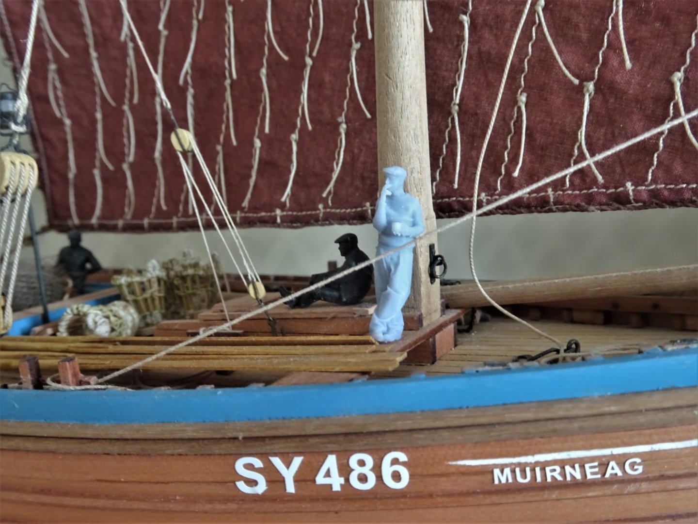
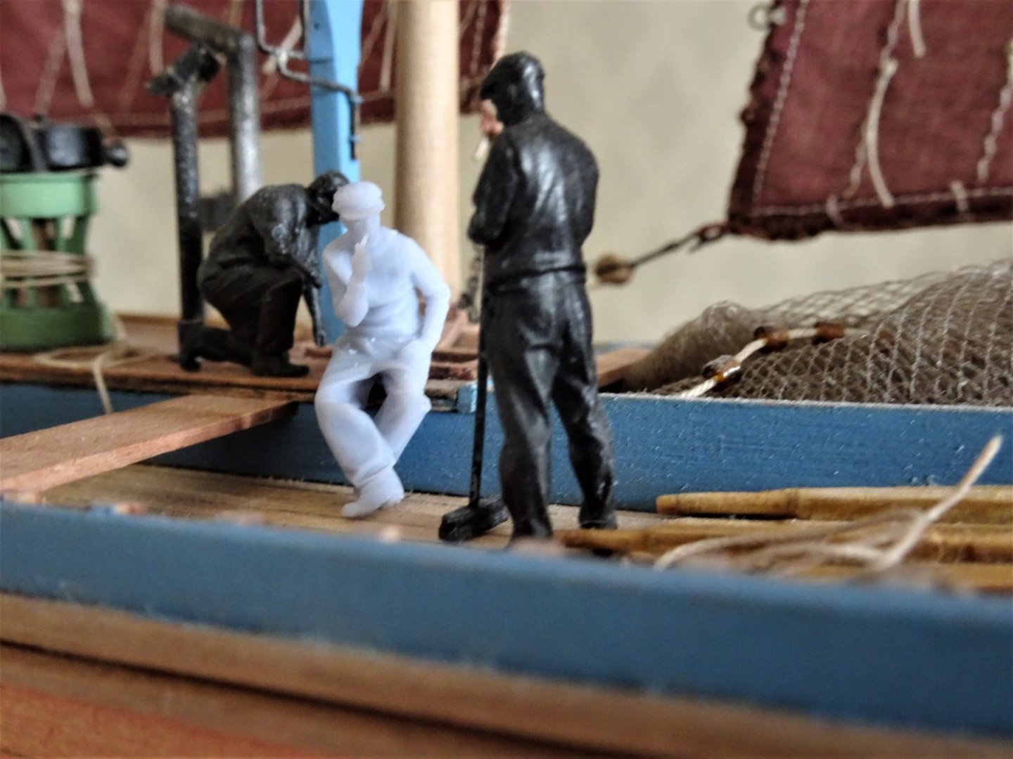
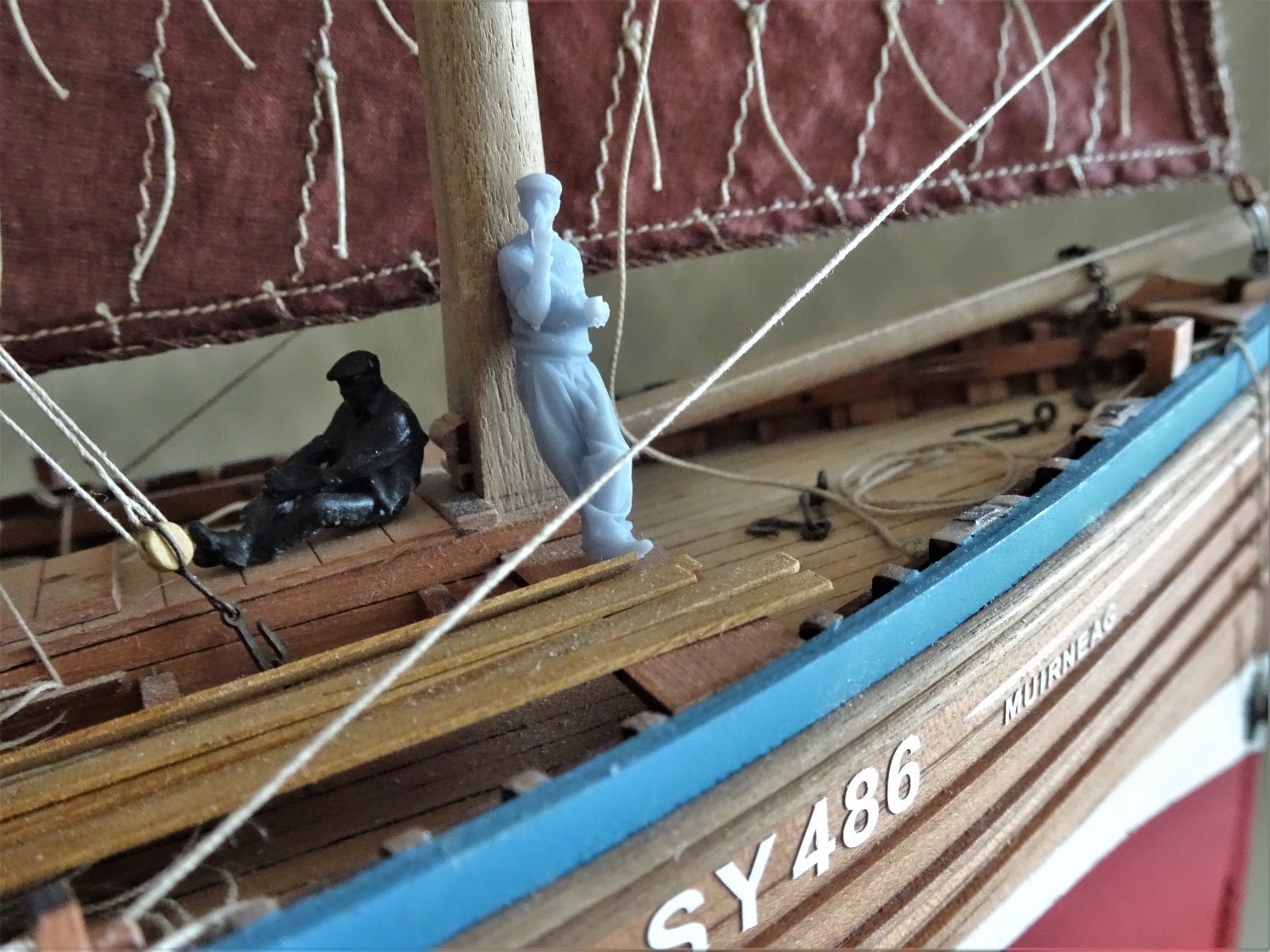
This is a heads up for Modelu scale figures. Shipping, Fishing, and Waterways – Modelu (modelu3d.co.uk) I have used Modelu figures to crew my Vanguard fishing boats, but in the absence of specific figures I used industrial figures. A while ago Modelu asked its customers what figures they would like modelling. More in hope than expectation I suggested fishing boat crew members, and to my surprise they have produced a set. 7810(2) I ordered a couple to add to my Zulu and Fifie builds. 7808 7806 A good fit to lean against the mast aboard Muirneag 7809 The figures are nicely modelled and are available at different scales. There are twenty figures in total in different poses. B.E.

.thumb.JPG.8463d1398352b67fdb25bcabb66e02c6.JPG)
- 2 replies
-
- 12
-
-
-
She’s looking excellent Ron, very nice detailing of Capt. Pennypincher, he looks a dead ringer for Russell Crowe, did he transfer from Surprise.😉 B.E.
- 542 replies
-
- 3
-
-
- Sphinx
- Vanguard Models
- (and 3 more)
-
Great looking set you have there Dan, they do make lovely models B.E.
- 14 replies
-
- 2
-
-
- lady isabella
- zulu
- (and 2 more)
-
Nice work Peter, she looks impressive. I like the sail arrangement on the Gardner painting; if you use silkspan sails they can be manipulated using the clews and Buntlines. It's been a while since I did sails on my Seventy-four build, but the silkspan is coated with diluted pva, re-wetted and hauled into shape. It then dries in the desired position. The same applies if you want a slight billow to the sails, heat applied from behind fixes the shape. I look forward to see her kitted out. B.E.
- 366 replies
-
- 1
-
-
- bellerophon
- victory models
- (and 2 more)
-
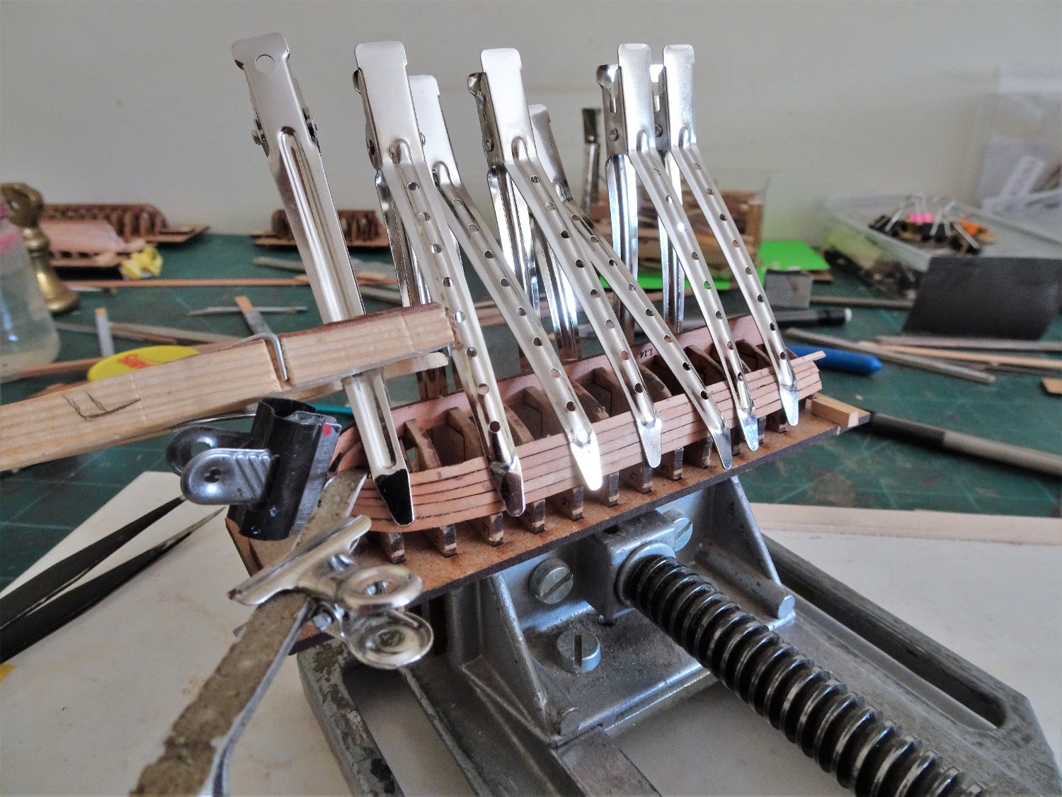
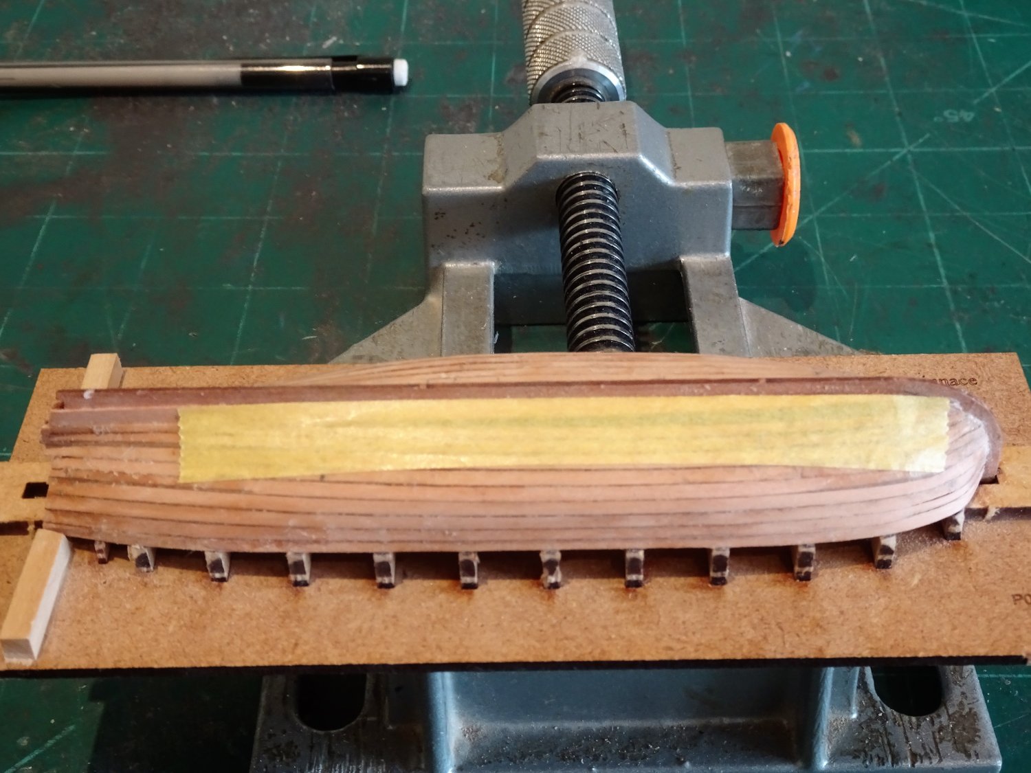
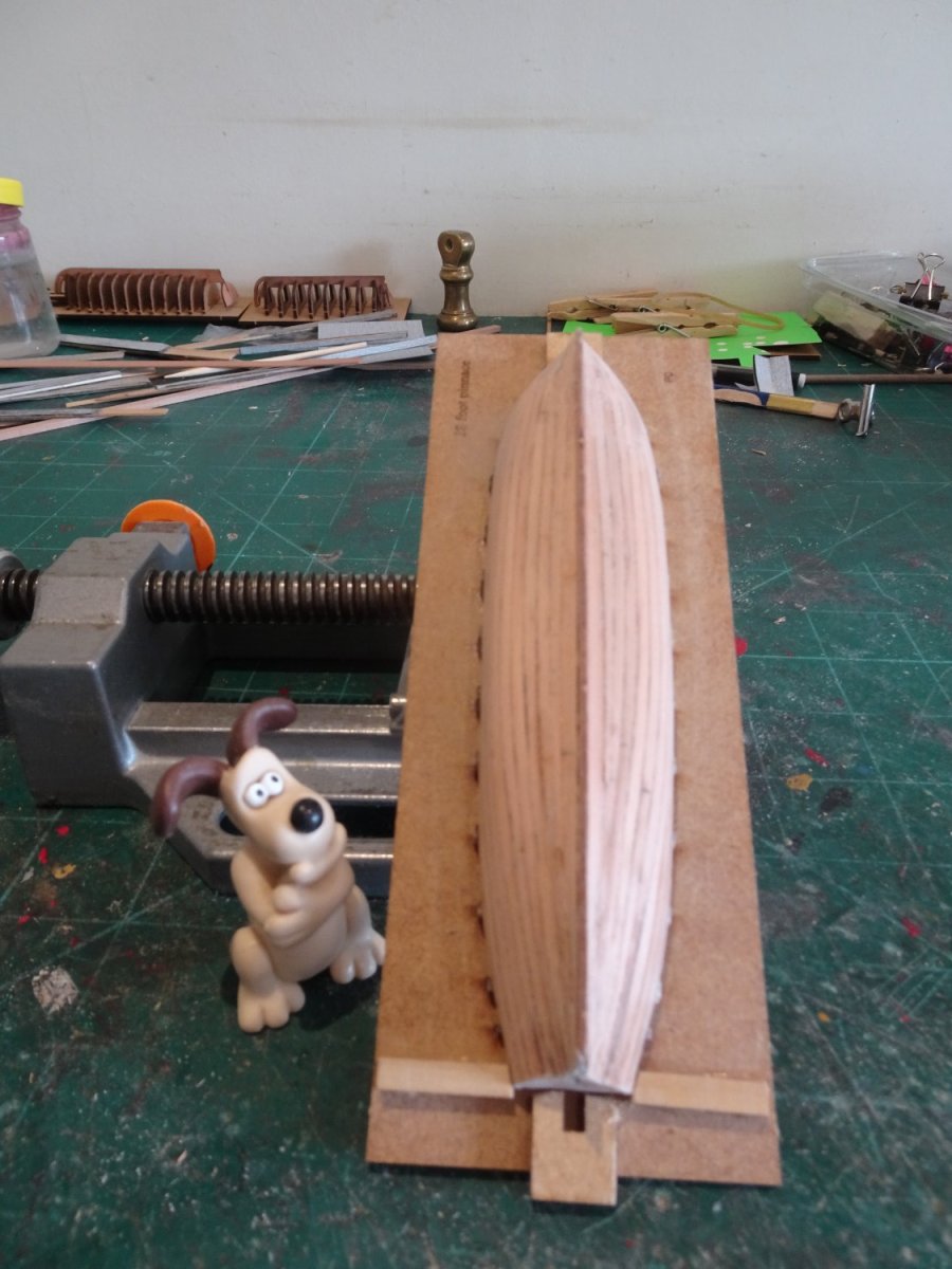
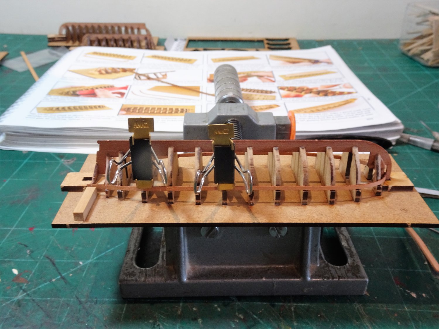
Thanks Rob and Thomas. Post One Hundred and Forty-eight Completing the Pinnace planking. The hull shape of a Pinnace at the bow make it not the easiest to plank. From the fifth strake these tiny strips are subject to the whole gambit of manipulation. Edge bend, taper, bevel, and bow curve. (other builds may differ) 7780 The edge bend required on the fifth strake. A couple of tips. It quickens the process if the wood is dampened when applying ca at the bow. 7783(2) These Hairdresser sectioning clips are perfect for clamps on these small projects. They exert just the right amount of pressure and can be bent to suit the job in hand. With six strakes completed I turn my attention to the Garboard strake. Tricky things Garboards, how much to taper, where to terminate? 7784 I start with a length of card to avoid spoiling my limited supply of 0.6mm strip wood. I am using slightly wider strips for the Garboard, but in practice it’s guesswork for me at the best, coupled with hope that the adjacent planking meets up. The aim is to get any awkward final spiled planks to sit beneath the round of the hull. 7786 Here there are two strakes remaining, and the spacing is fairly even. 7787 The final spaces requiring spiled planks which will sit out of sight beneath the hull. 7789 Tamiya tape is used to template the final planks. 7798(2) 7791 As is my practice I refer to Gromit for an opinion. 7796(2) How does it look Gromit – Ruff comes the reply. Have faith Gromit it will all come good in the end.🤞 🤞 Onto the Launch. B.E. 02/08/2022

.thumb.JPG.e67cf762704fdc0357ffa3bbf0d1e397.JPG)


.thumb.JPG.111d9791ea0e9c7cb65973cc0c7bd0c0.JPG)
.thumb.JPG.5b0ab82a7f97237bec044e24691b6441.JPG)
- 857 replies
-
- 19
-
-
-
- Sphinx
- Vanguard Models
- (and 1 more)
-
Whaler copper weathering
Blue Ensign replied to Srodbro's topic in Painting, finishing and weathering products and techniques
Great shots of coppering Bob, thanks. I would agree the model coppering on that Morgan model looks more stylised that authentic, it's not a look that appeals to my eye. B.E. -
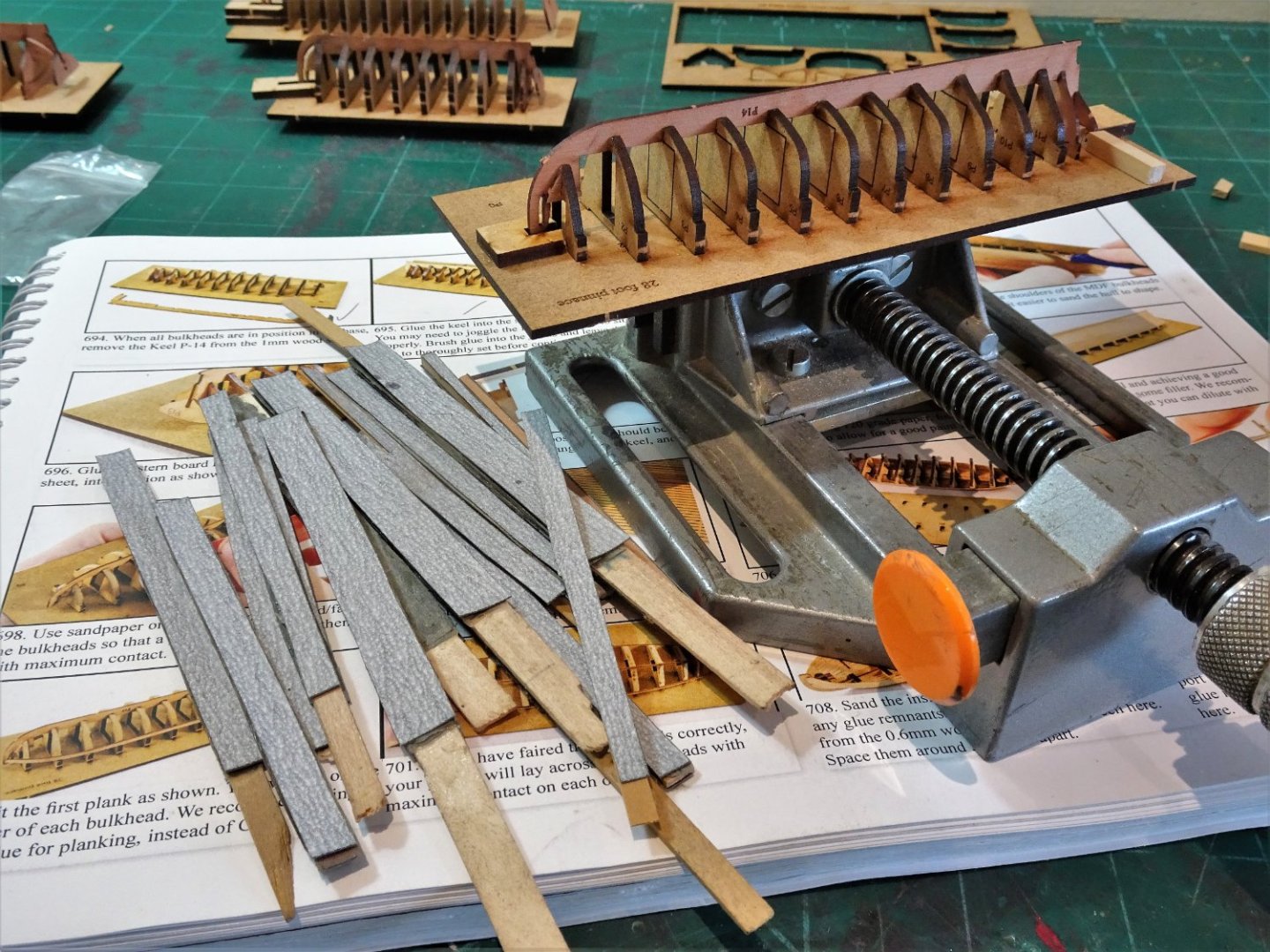
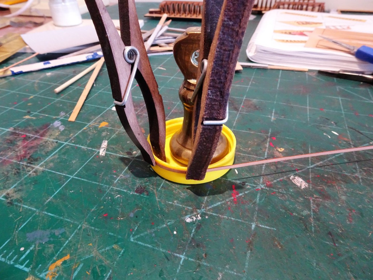
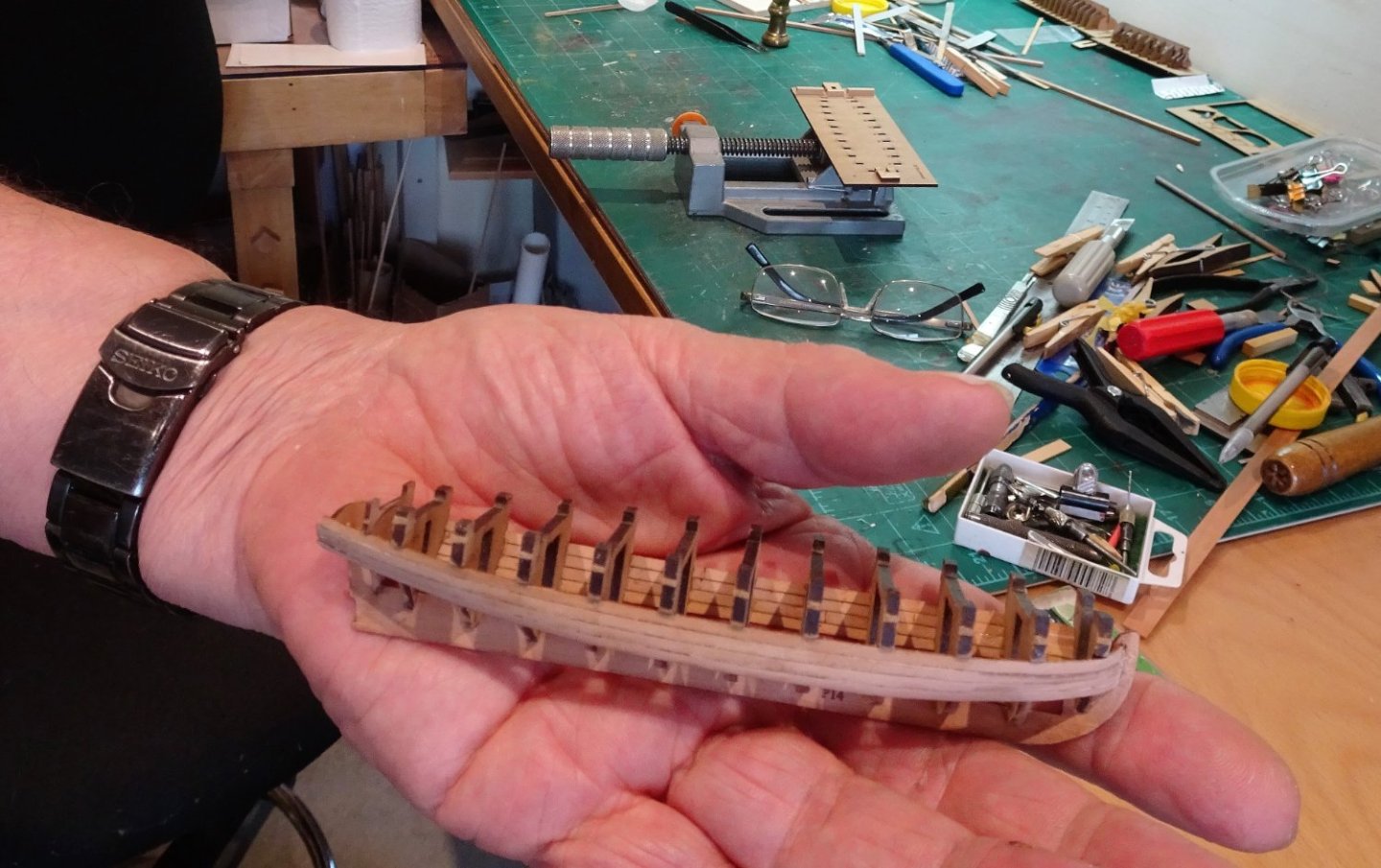
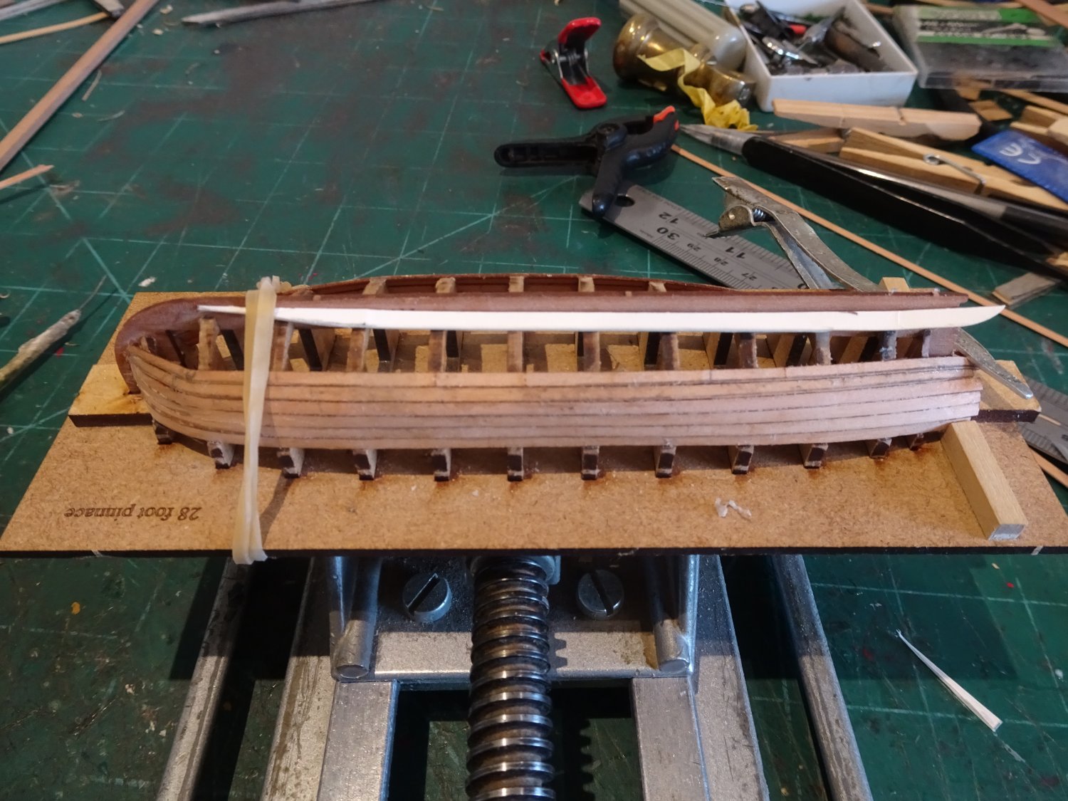
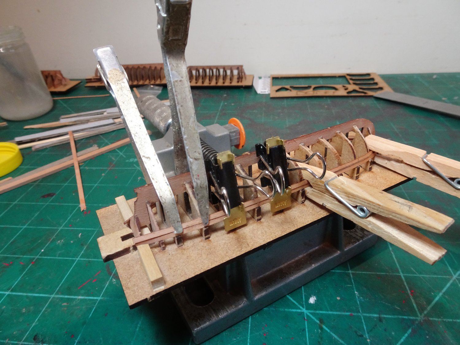
Post One Hundred and Forty – seven Prepping and fairing the hull. I begin with the Pinnace Preparation is everything and I take steps to reduce the risk of damage to the vulnerable areas of stem and stern. Of course you may get away without this stuff but I’m a belt and braces sort of chap. 7714(2)p I also apply a smear of pva beneath four of the tabs to help stabilise the frames in the building board. This is easily removed later. 7724 A fresh supply of sanding sticks is made up for the fairing. 7741(3) The hull is stable on its board allowing me to handle it with confidence and the fairing doesn’t take that long. The first plank is applied against the shoulder of the frames and fits into the stem rabbet. 7747 Heat is used to form the bow curve. 7753 This probably the easiest plank to fit except that getting the first plank to just hold in the stem rabbet whilst allowing space for the corresponding plank is tricky. 7752 My approach was to get the end sufficiently in to hold and then trim back in the rabbet from the other side for the corresponding plank. I used a spot of ca for the bow end and first frame and pva thereafter. 7751 I am surprised that the length of the planking strips only extends about 2mm beyond the stern, leaving very little excess for minor adjustments or securing at the transom. It also makes edge bending as a planking tool, more difficult. 7756 The support blocks used to stop lateral movement of the stern panel are trimmed to form clamps for the plank ends. After the first strake the planks are tapered at the bow. When I say tapered this is a very slight taper – the overall width of the planks is less than 2mm so there is little to play with. At this scale the finer points of hull planking such as tick strip marking don’t really apply, at least for me. The start of taper can be marked but beyond that it’s down to eye and trial fit. When it comes to edge bending the strip are too small for easy clamping, but they are fine enough to work an edge bend using fingers, but it is a high risk activity. At this point I have already had three strip breakages but fortunately there is a supply of 0.6mm fret from the Sphinx kit to make replacements. 7757 One has to get inventive when it comes to clamping on these bijou constructions. 7759 Four strakes fills the Stem rabbet, from this point on they will terminate against the stem/keel. The stem is now more secure from the risk of breakage. 7760 With four strakes attached to the stern board it is now also secure. 7770 The hull is quite rigid now and can be removed (temporarily) from its building board if required. I will now continue planking to completion. B.E. 30/7/2022
.JPGp.thumb.JPG.6c50fb359fd6ab74de7b5bd5b2dc1b20.JPG)
.thumb.JPG.27bf371e3a22d8dbddc7203e04ec65f6.JPG)


- 857 replies
-
- 21
-
-
-
- Sphinx
- Vanguard Models
- (and 1 more)
-
Well done Mario, she looks good.👍 Nothing like completing a satisfying build to encourage you onto the next. B.E.
- 27 replies
-
- 1
-
-
- Lady Isabella
- zulu
- (and 2 more)
-
Nice touch including the Pump dales Yves, have you left the Royal cipher on the guns bright for artistic preference? B.E.
-
Thank you Rob, If you knew me, relaxed is not one of my personality traits. If I appear so, it is probably born of previous experience of building these little beggars, two scratch built at 1:64 and two of Chris's kits. They are fiddly to make and bits can break with so much as a harsh look, and I can see that they would be a challenge for a novice builder, they're still a challenge for me now. They do however, make up into fine little boats, and I'm quite a fan of them, so much so that only yesterday I ordered the 36' Admirals Barge to add to my collection. I will then have the full set of types. The only thing missing from Chris's line- up is a Longboat, and should he add one I will be up for that as well. I had a peek at your cutter and she looks just fine.👍 Cheers, B.E.
- 857 replies
-
- 4
-

-
-
- Sphinx
- Vanguard Models
- (and 1 more)
-
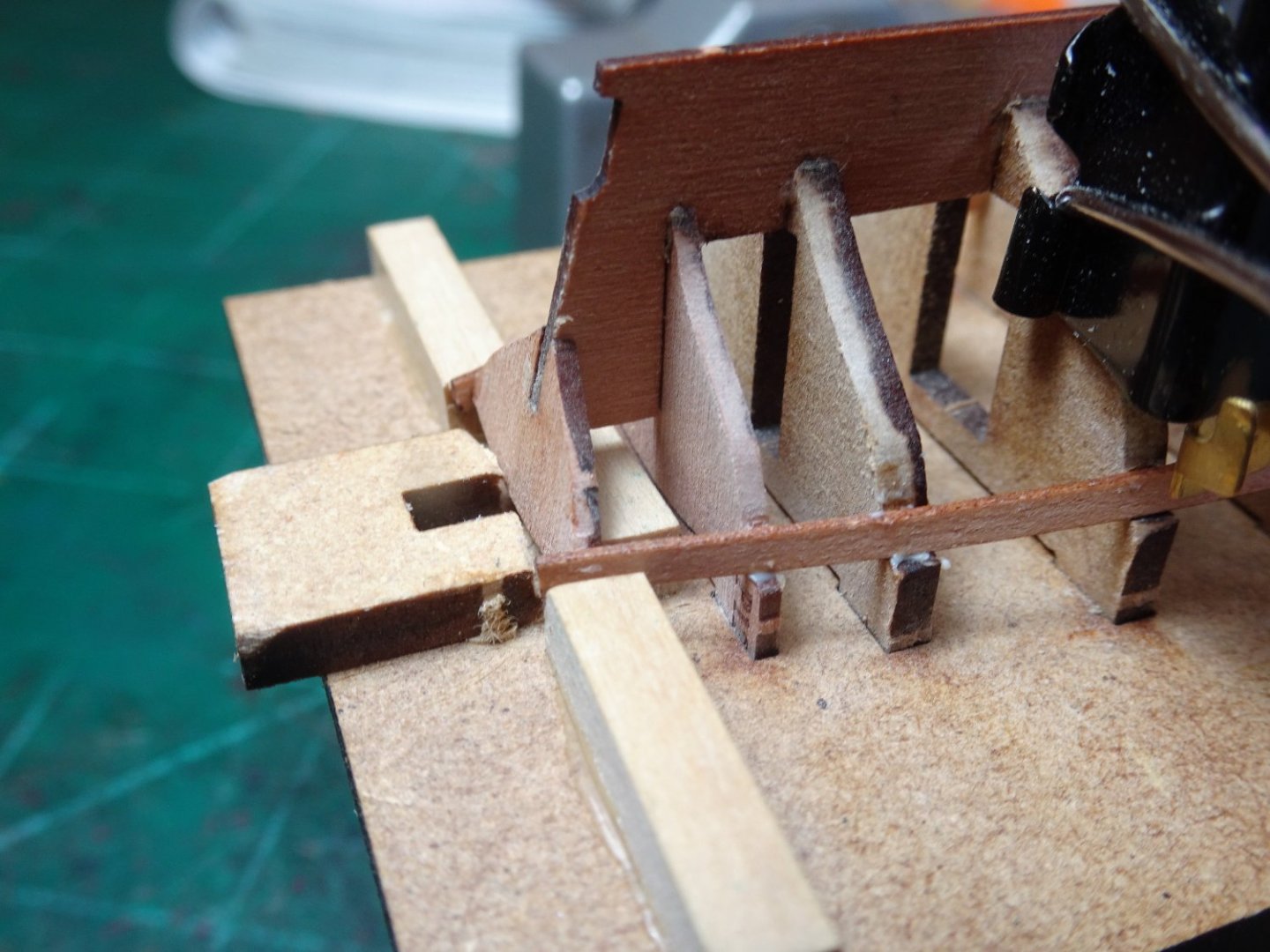
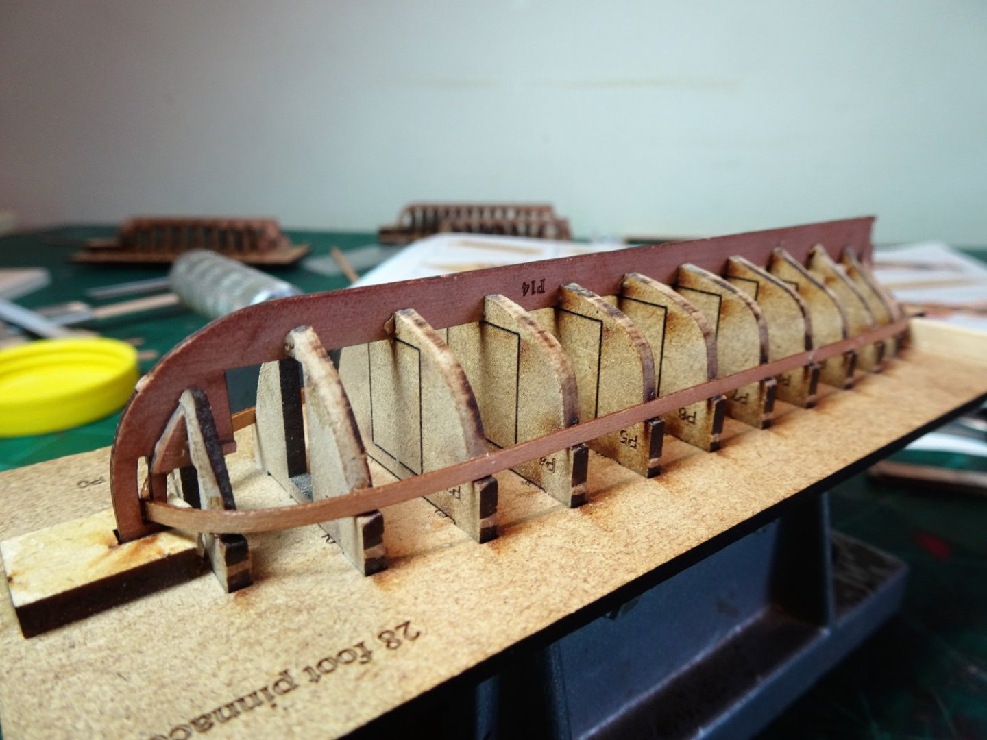
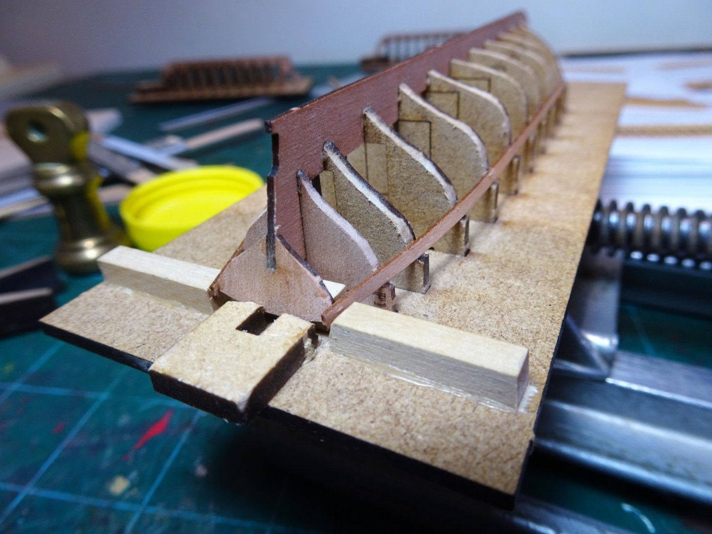
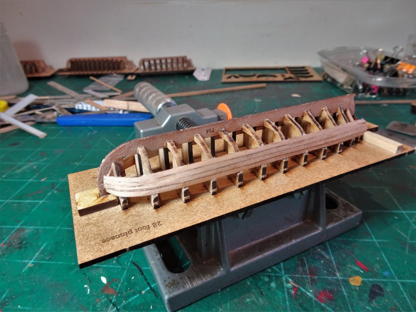
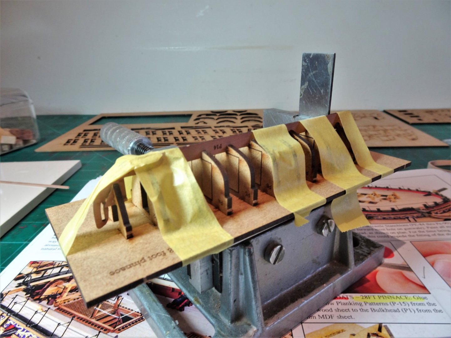
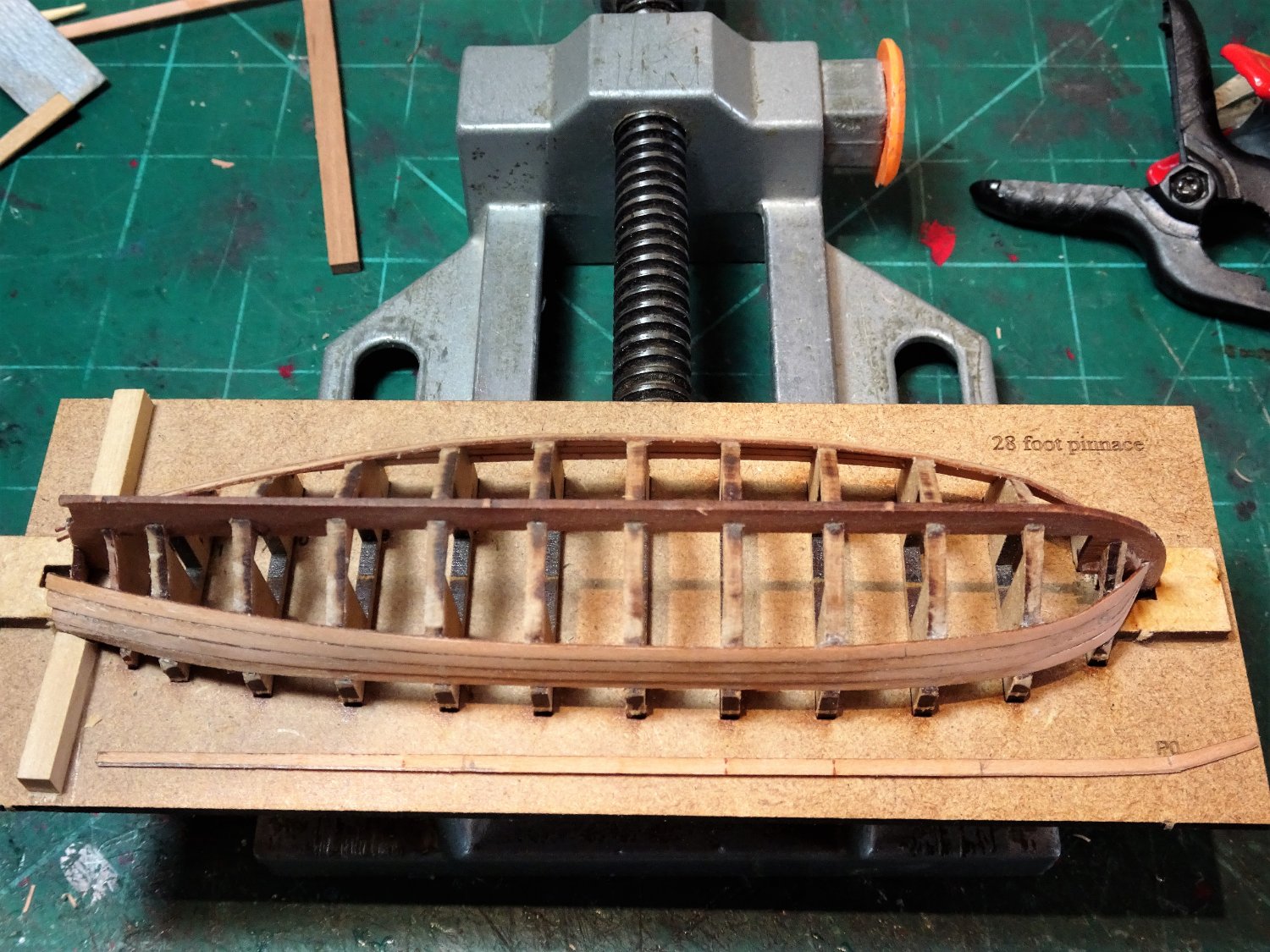
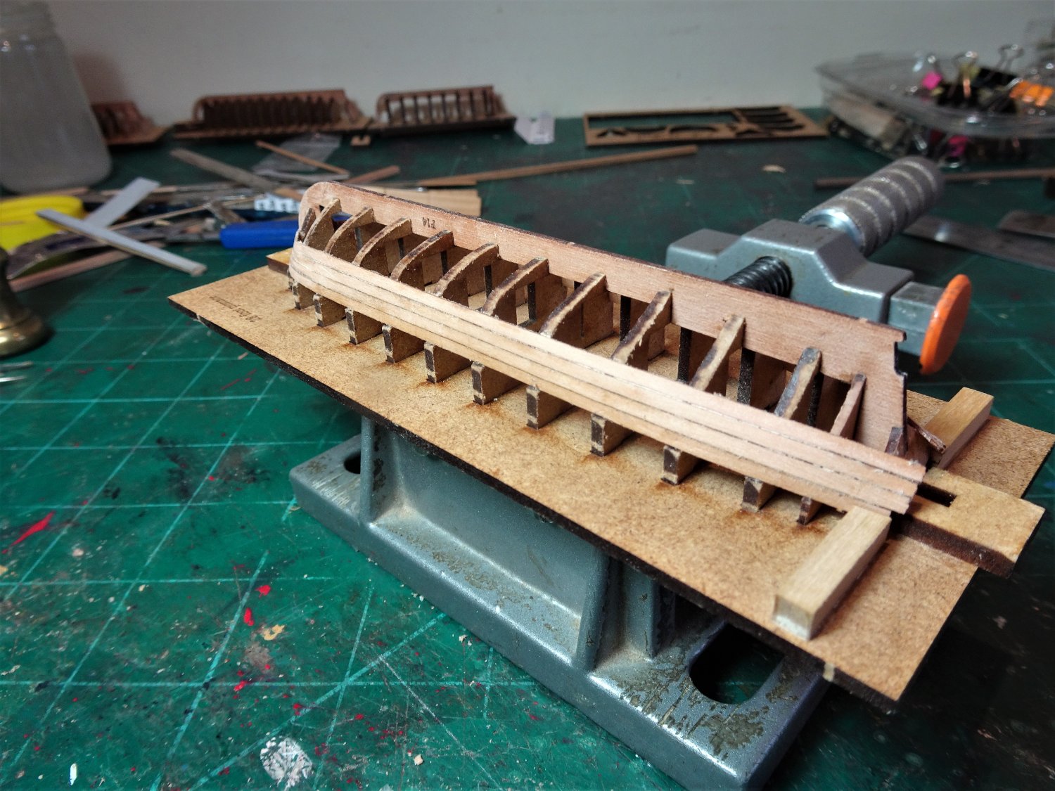
Thank you Bob. Post One hundred and Forty-six The Ships boats. The boat allocation for Sphinx Chris has generously provided three boats to adorn Sphinx. A 28’ Pinnace, 24’ Launch’ and 22’ Yawl. This follows the allocation indicated in the AotS book for the 24 gun Frigate Pandora which also had an additional Yawl and an 18’ cutter. This is slightly out of sync with the official boat establishments, but Pandora was on a specific mission, and her establishment is a matter of record. Despite establishment allocations for different classes of ships, Captains were allowed to petition for alternatives, so I doubt anything was really set in stone, and that wonderful phrase ‘subject to the exigencies of the Service’ comes to mind. I am not exactly unfamiliar with these boat kits having built both the Yawl and cutter previously, but they are nice little projects and I look forward to including them with, if not on, my build of Sphinx. I did a separate log in relation to the Yawl and cutter last year detailing my experience with these bijou kits. 18th c Ships boats by Blue Ensign – FINISHED - Vanguard Models -1:64 - - Kit build logs for subjects built from 1751 - 1800 - Model Ship World™ I am also going to include an 18’ cutter which I happen to have lying around and have decided to set up all four at the same time. To deal with these kits a soft hands approach is essential and a good supply of mini sanding sticks. I make mine by sticking strips of 320 paper to planking strips. I begin with the Pinnace. First steps A grip block is glued beneath the building board to hold the assembly in a vice. The twelve frames fit loosely in the board slots, but they do need a little play to allow for aligning the Pear keel piece. I found that Frame 1 at the bow required the slot sanding to allow fitment of the forward end of the keel. Exert pressure at your peril! I found it quite fiddly to get the keel to seat properly down on the frames. I did quite a few dry runs before committing to glue, the bally frames kept jumping out of their slots. 7662 I found it helped to use Tamiya tape to hold the keel and frames in place as I progressed aft seating the keel. The Launch proved much easier to attach frames and keel but in removing the keel from the fret the stern post just fell apart at the middle point, the curse of horizontal grain. All is not lost tho’ because adding the stern board (L13) helps secure the re-glued part. The Yawl went together well but care has to be taken with the bow fillers (Y13), careful easing before fitting is recommended. I am also keeping a wary eye on the bow stem which as I recall from my previous build resulted in a new scratch part being made. The Cutter (which does not form part of the kit allocation) is the Mark11 version. My previous build was the original version which lacked the finesse of the current model. As with the original I may well clinker plank the cutter as was the style. 7665(2) An afternoons work gets the basics done and I will now operate a sort of production line to completion. The system should reduce the overall build time for the set. B.E. 29/07/2022
.thumb.JPG.bbfa5a63ae4557aa3ce7deb40caccf5b.JPG)
- 857 replies
-
- 14
-
-
- Sphinx
- Vanguard Models
- (and 1 more)
-
Every time I dip into your log Marc I am blown away by the pure artistry of your work. You are producing one of the most beautiful models I think I have ever seen. Regards, B.E.
- 2,699 replies
-
- 7
-
-
-
- heller
- soleil royal
- (and 9 more)
-
I don't know what all that means and given that I started communication using a stick with a scratchy nib and ink pot, one step removed from a quill, I constantly find myself amazed that I even find my way on here at all. I am more than happy to rely on James, for all things MSW computer, and many things modelling. Thanks James. B.E.
-
Thank you, Glenn UK, Glenn USA, Kirby, Ron, Marc, Rusty, and Thuky, for your supportive comments and for all the ‘likes’ @ Glenn USA - as someone who admires the superb quality of your work, your words mean a lot to me. I put a lot of effort into the headworks, scrolls and friezes, and I’m pleased how it turned out. I also have Chuck to thank for the stern decorative panels. @ Ron - Thanks for your input, always welcome, I was thinking of displaying the boats separately within the case, but I won’t be able to resist at least trying the Pinnace on the skids. I too am interested in how your Camilla will look in her watery setting, on the basis of your previous examples I think she will look amazing. @ Thuky - I think you already are, I can see you have the mindset for this malarkey, your willingness to re-work your Alert stern is the mark of the dedicated ship modeller who is bound to succeed. B.E.
- 857 replies
-
- 4
-
-
- Sphinx
- Vanguard Models
- (and 1 more)
-
You really shouldn't have to work that hard to achieve a good result with those Quarter Galleries Yves, I agree they would be so much better in printed resin. Perhaps someone from CAF will see your comments and address the situation. The QG construction is so complex and poor materials are not what you want. Still a model is more than the sum of its parts and once you've worked your magic such deficiencies will tend to fade into the background. B.E.

.JPG.c610422149fa3fa5ab651b3160010001.JPG)
.JPG.6a2985193e86f78e1810789c3ad5da18.JPG)


.JPG.b5630e02f8fb06bf4a992a73c224853f.JPG)
.JPG.809a85957168529c12c0367a21f71047.JPG)
.JPG.86aefe69c15f92aa92c6e29bd9f6b6c3.JPG)


.JPG.fe18ef8201658444ca16d311a4640543.JPG)
.JPG.b84e09b683fedeab041ce28163d5f1d7.JPG)


.JPG.89971776069359065c03be9d22a04bd3.JPG)
.JPG.d46ed1b7baed83677ab7556f4089ec99.JPG)
.JPGp.JPG.ca75d24a0f64903ce61d0dfbf54fd64d.JPG)

.JPG.48000e5c65d0f4abbe3387345d60784f.JPG)


.JPG.ff5bda0440c6f6e0e18c09534c84ace0.JPG)