
HOLIDAY DONATION DRIVE - SUPPORT MSW - DO YOUR PART TO KEEP THIS GREAT FORUM GOING! (89 donations so far out of 49,000 members - C'mon guys!)
×
.JPG.ca33079f5815b861e67b9c2cccd37982.JPG)

Blue Ensign
-
Posts
4,566 -
Joined
-
Last visited
Content Type
Profiles
Forums
Gallery
Events
Everything posted by Blue Ensign
-
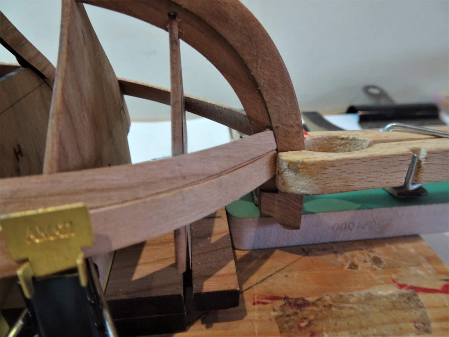
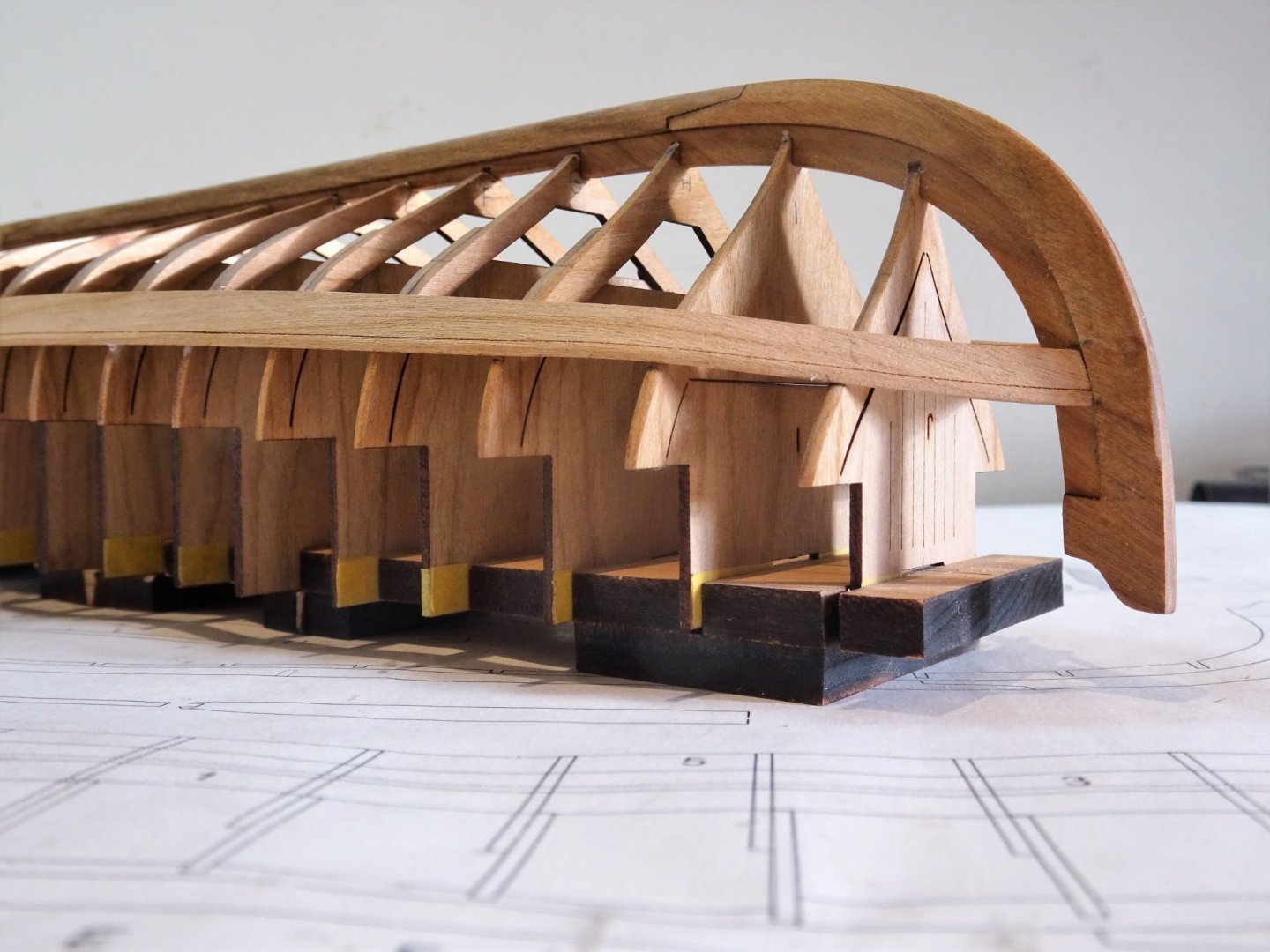
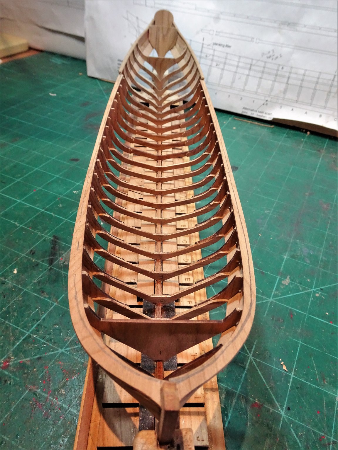
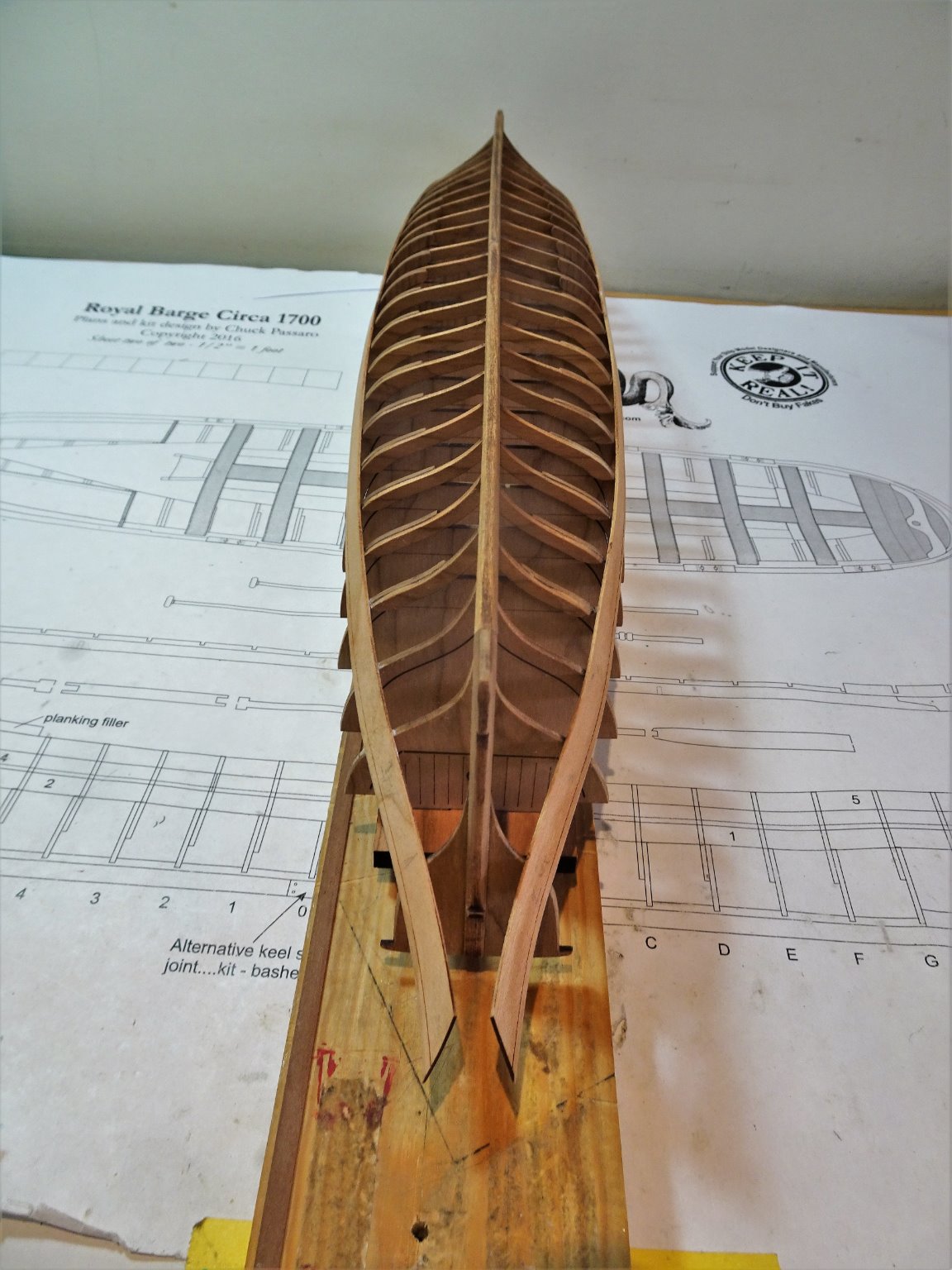
 Thank you Rusty.👍 Post Fourteen Fairing and thinning. I felt myself getting a touch of the modelling yips trying to decide on the best approach to this task. At first glance the fining down of the frames and thinning of the rails seems a task fraught with danger given that there are some 46 delicate frame sides to reduce to a uniform and elegant shape. I decided to start at the stern area taking in the aftermost five frames. 1410 I am using a No11 scalpel blade to pare away in an upward motion to achieve a narrowing curve up to the rail. This reduces sanding time, creates a nice clean line, but has its risks in that I am working with the blade coming towards my steadying fingers at the rail. For this reason, a fresh blade is used every two or three frames, keep it sharp, keep it clean. 1411 Once I have pared down the frame to rail level, I sand the rail horizontally and repeat the exercise. I use a pair of dividers set a tad over 2mm to score the width of the rail which I then line with pencil as a guide. I picked up on Rusty’s log where he describes his use of a simple width gauge to check the rail width as he progresses. 1412 The difference to the yet unworked frames is clear. At this point I decided to move forward to the following frames and reduce them to the same degree before returning to fine tune the whole set. 1413 In my next post I hope I will show the successfully completed frame reduction task, but this may take some time. Cheers, B.E. 29/03/21
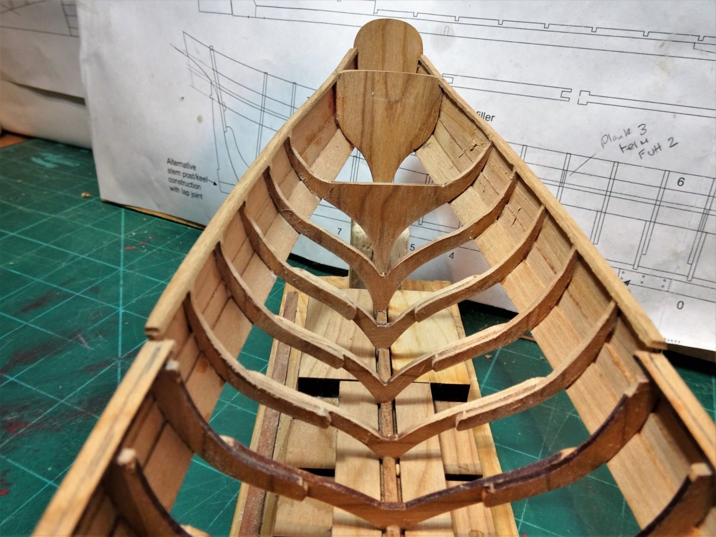

- 185 replies
-
- 13
-

-
- queen anne barge
- Syren Ship Model Company
- (and 1 more)
-
You and David are surely a ship modelling dream team, beautiful work Greg. Is that a seat of ease, or a pisdale located in the bow bulwark? B.E.
-
Set of the sail looks good Erik, very nicely done. 👍 B.E.
- 222 replies
-
- 1
-
-
- First Build
- Lady Isabella
- (and 2 more)
-
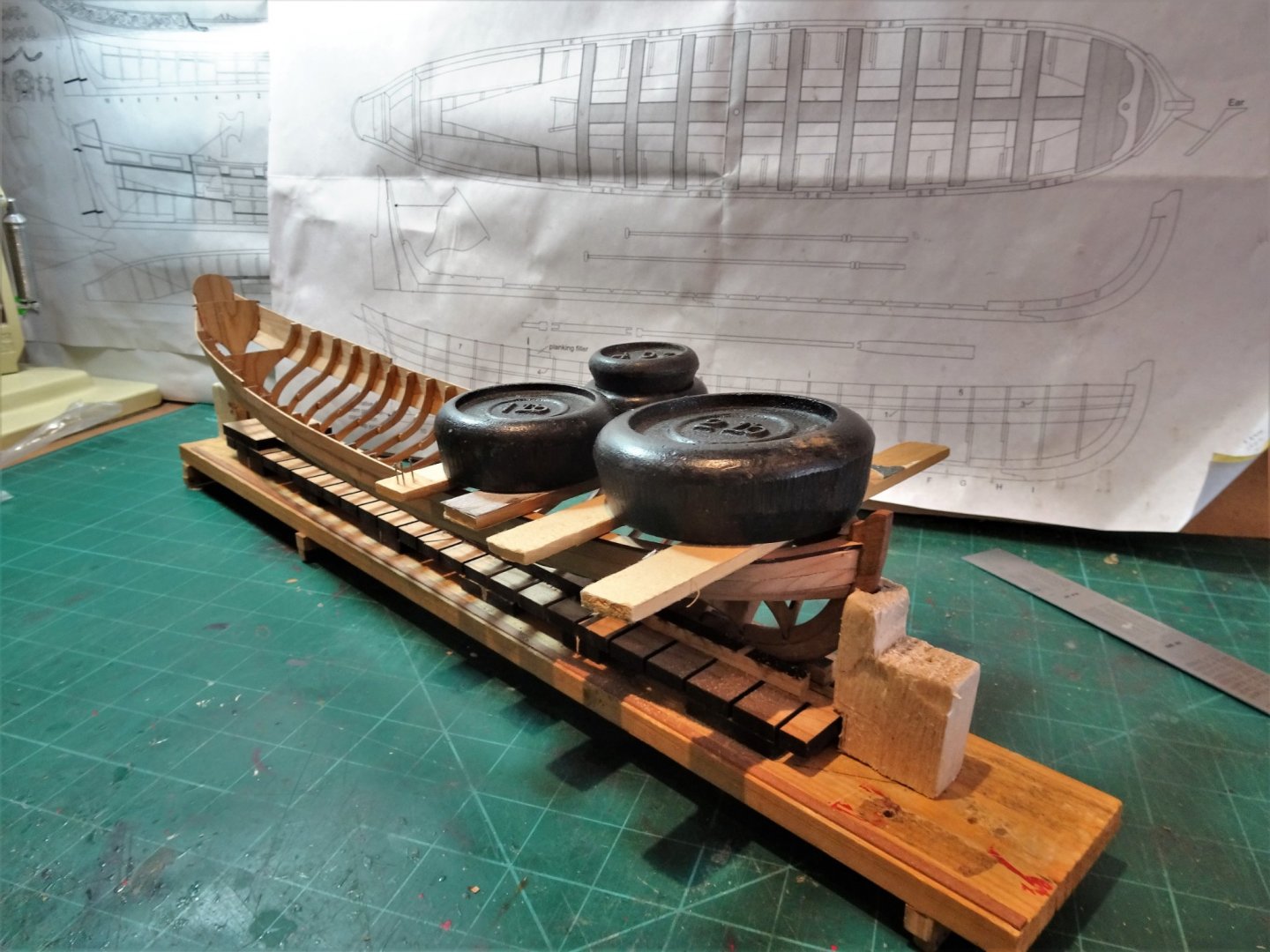
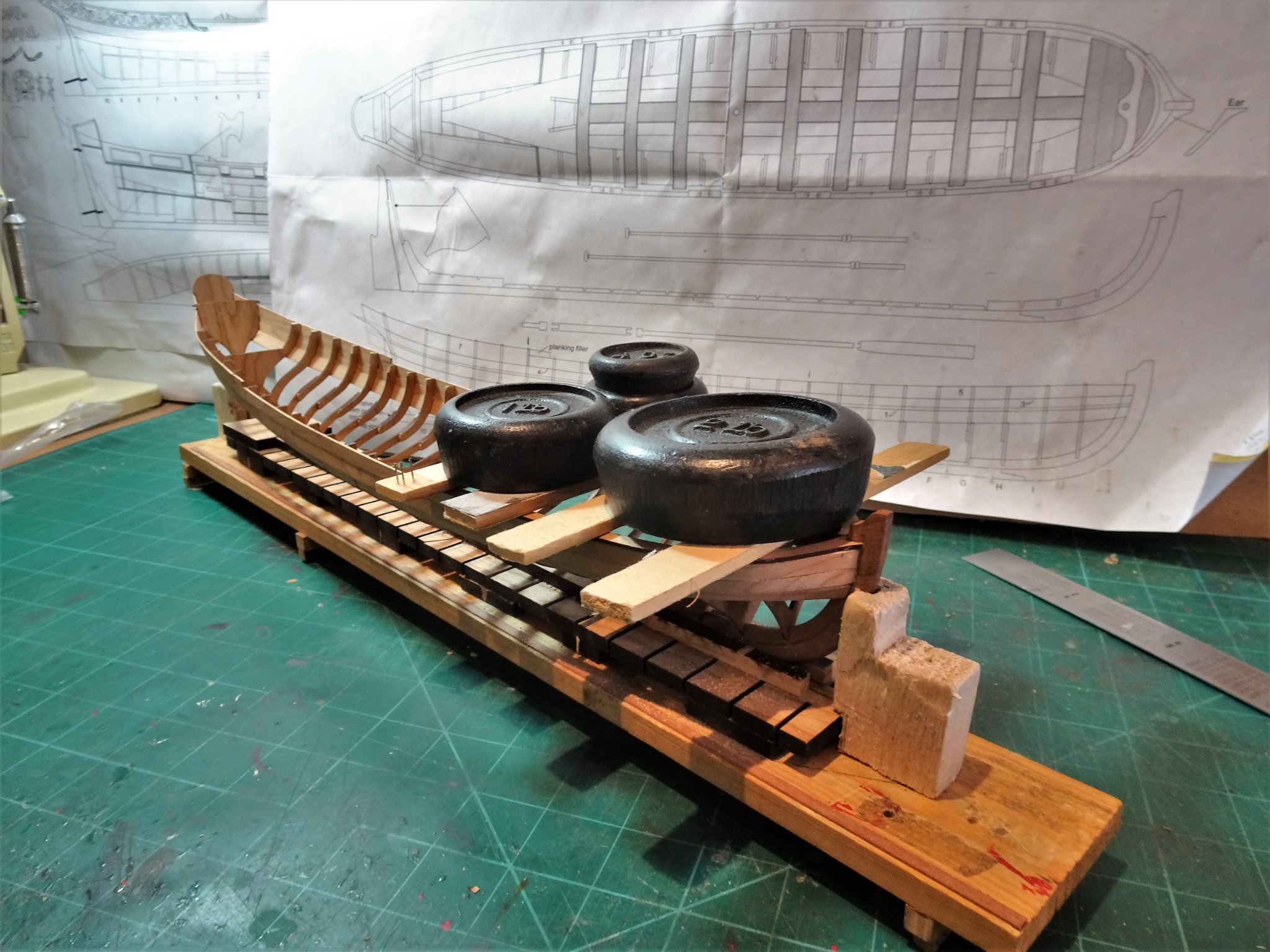
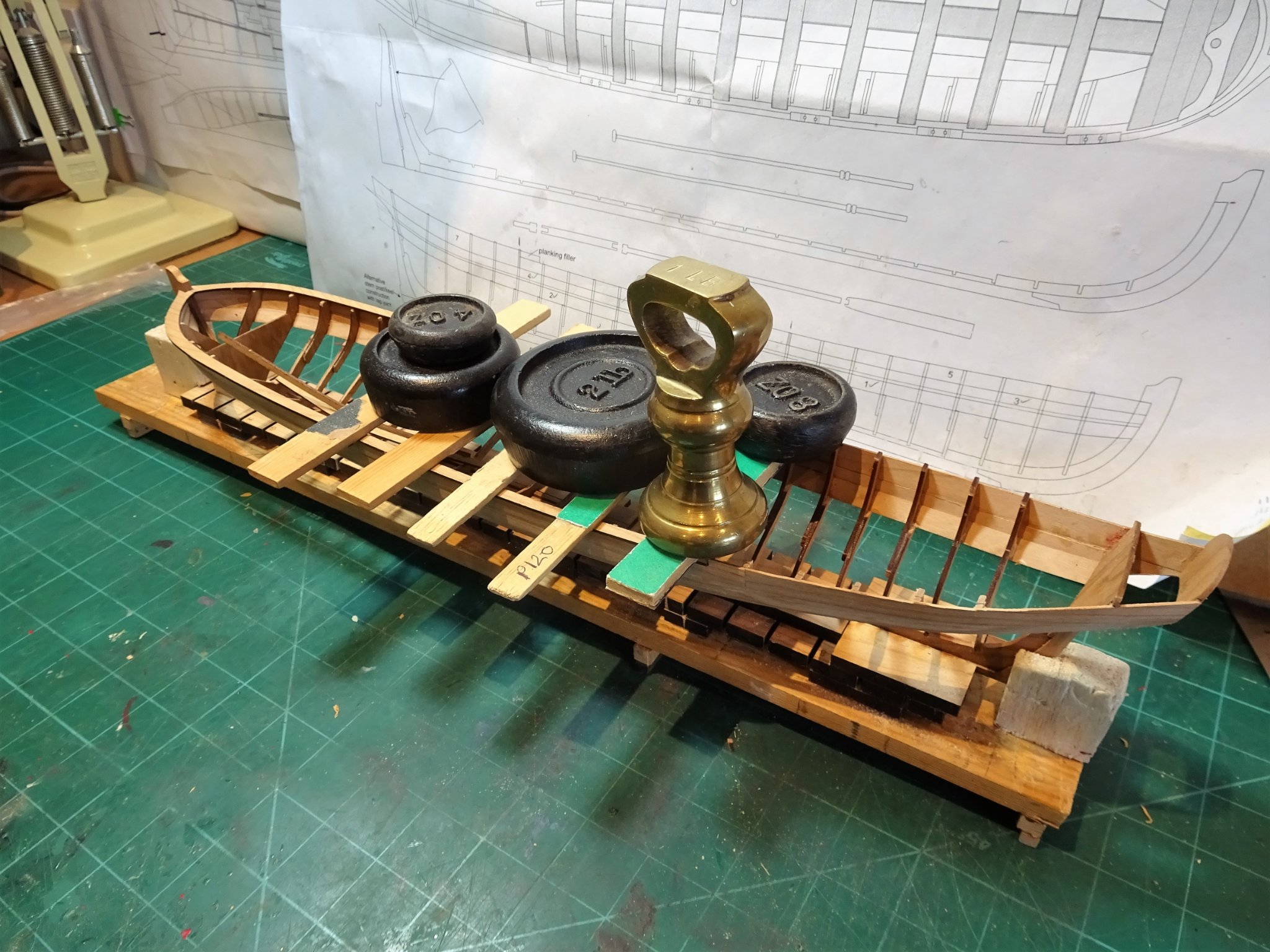
Ha, Ha, Bruce, testimony to Chuck's design, I think she'd stand more than a 2lb weight, but I'm not about to push it. 😉 B.E.
- 185 replies
-
- 1
-

-
- queen anne barge
- Syren Ship Model Company
- (and 1 more)
-
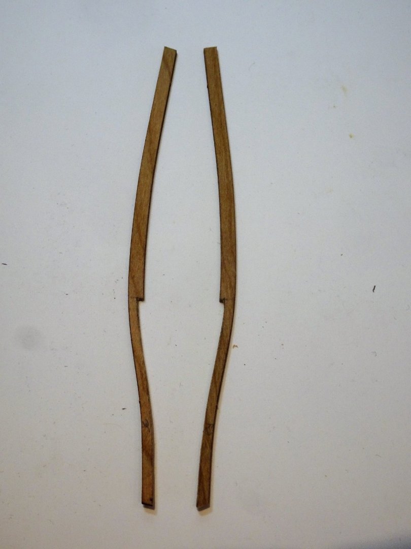
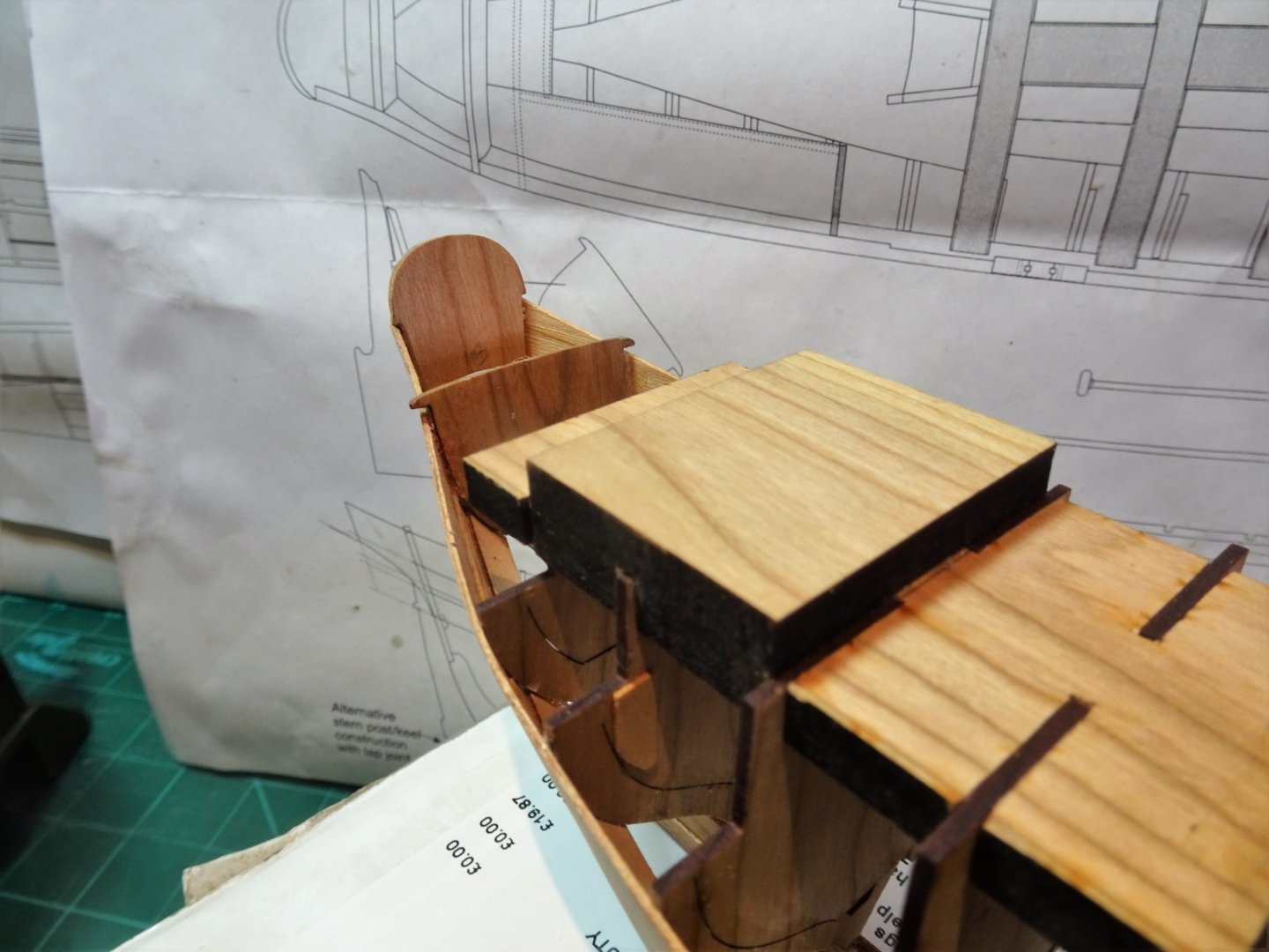
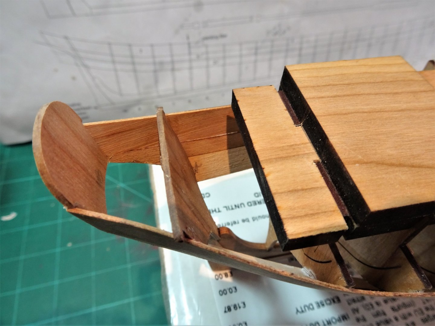
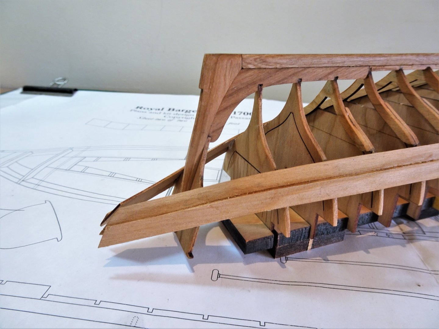
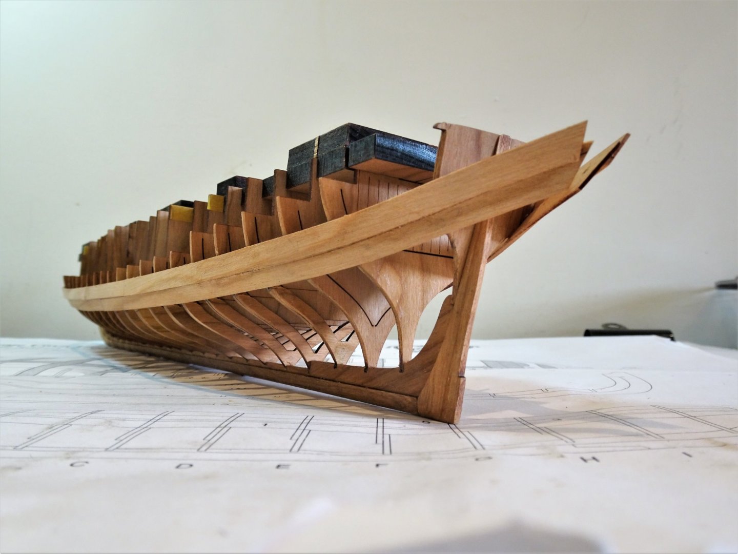
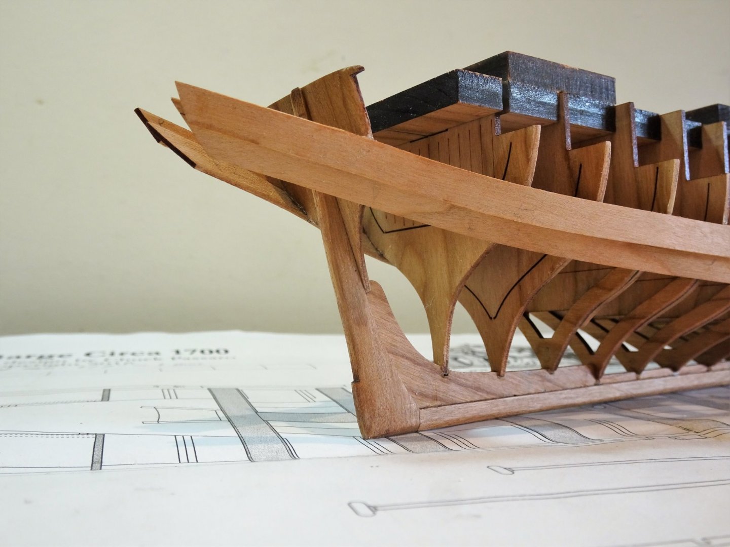
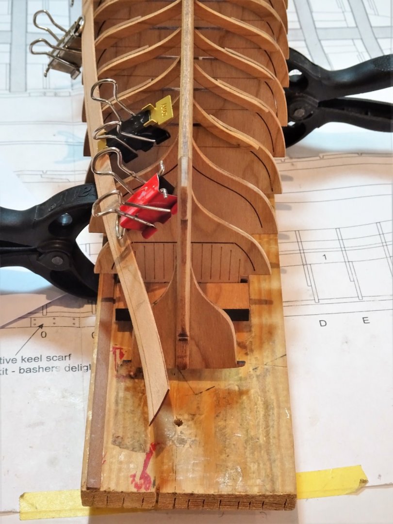
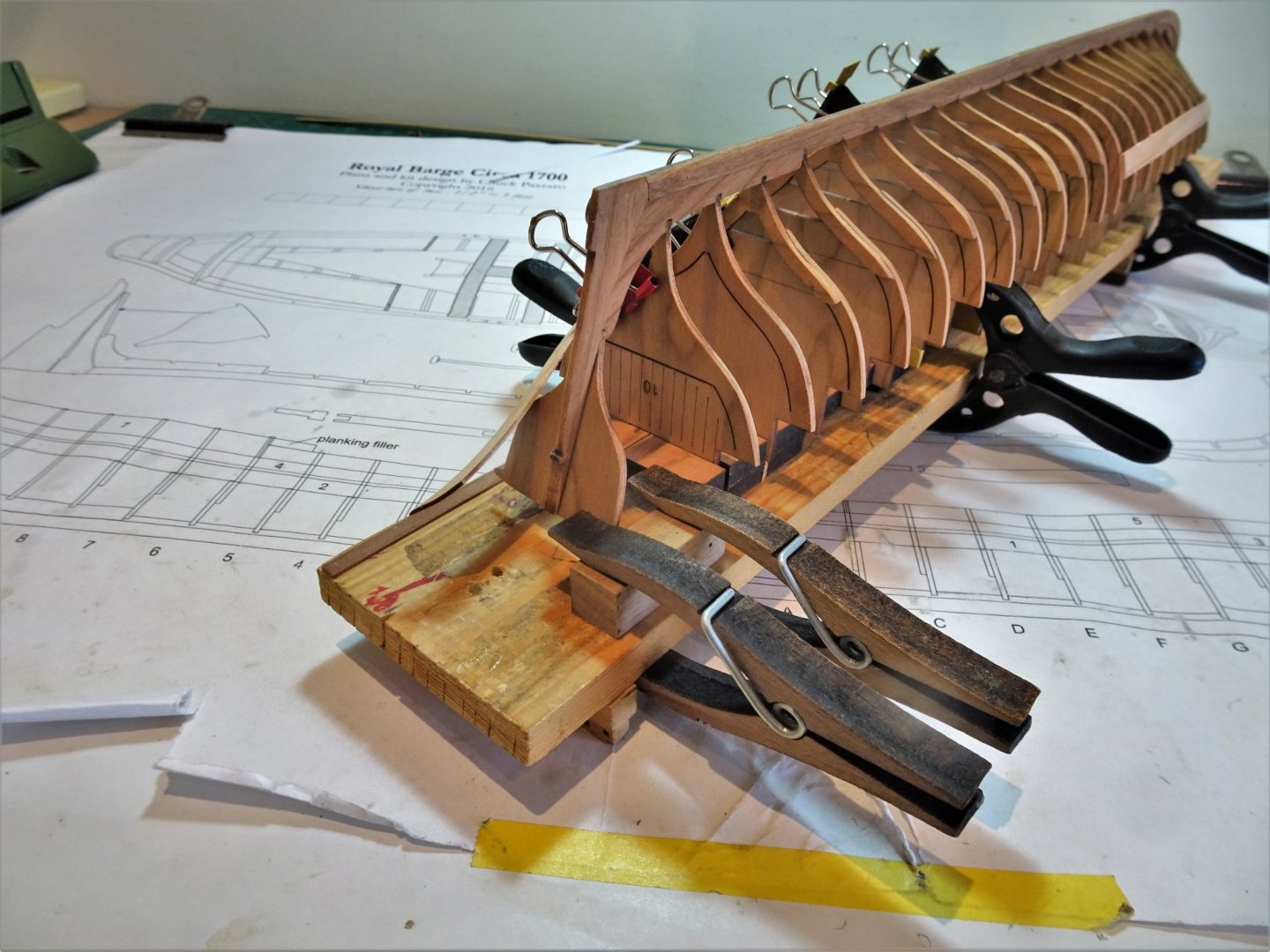
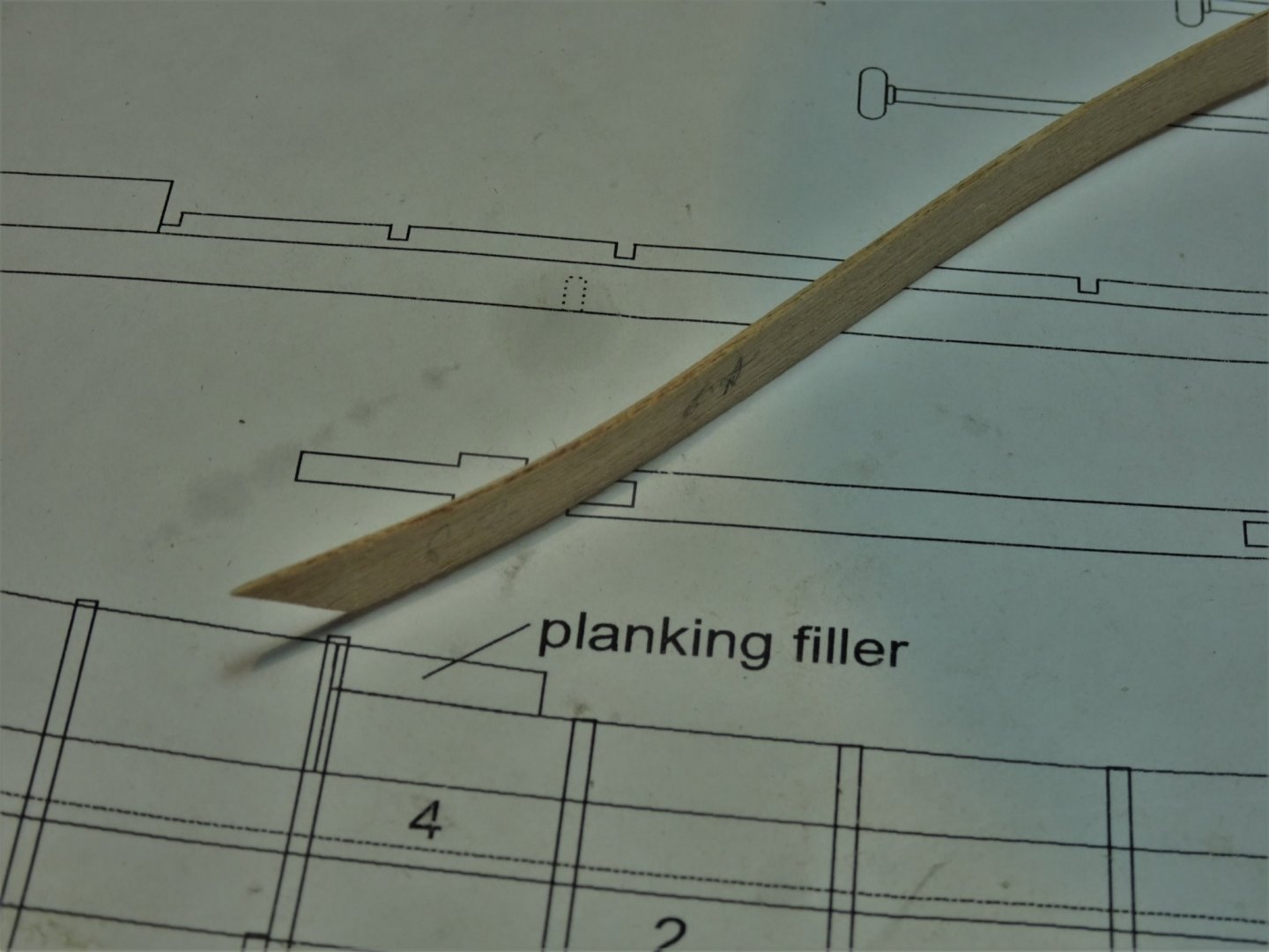
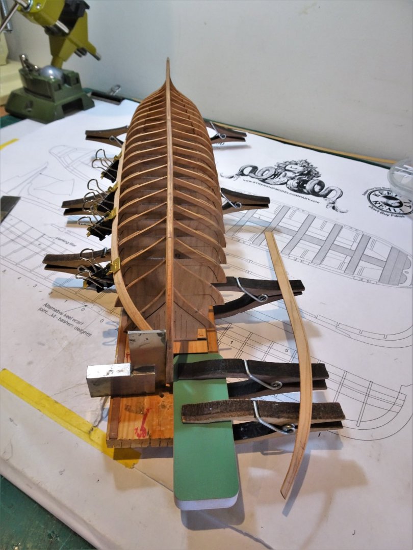
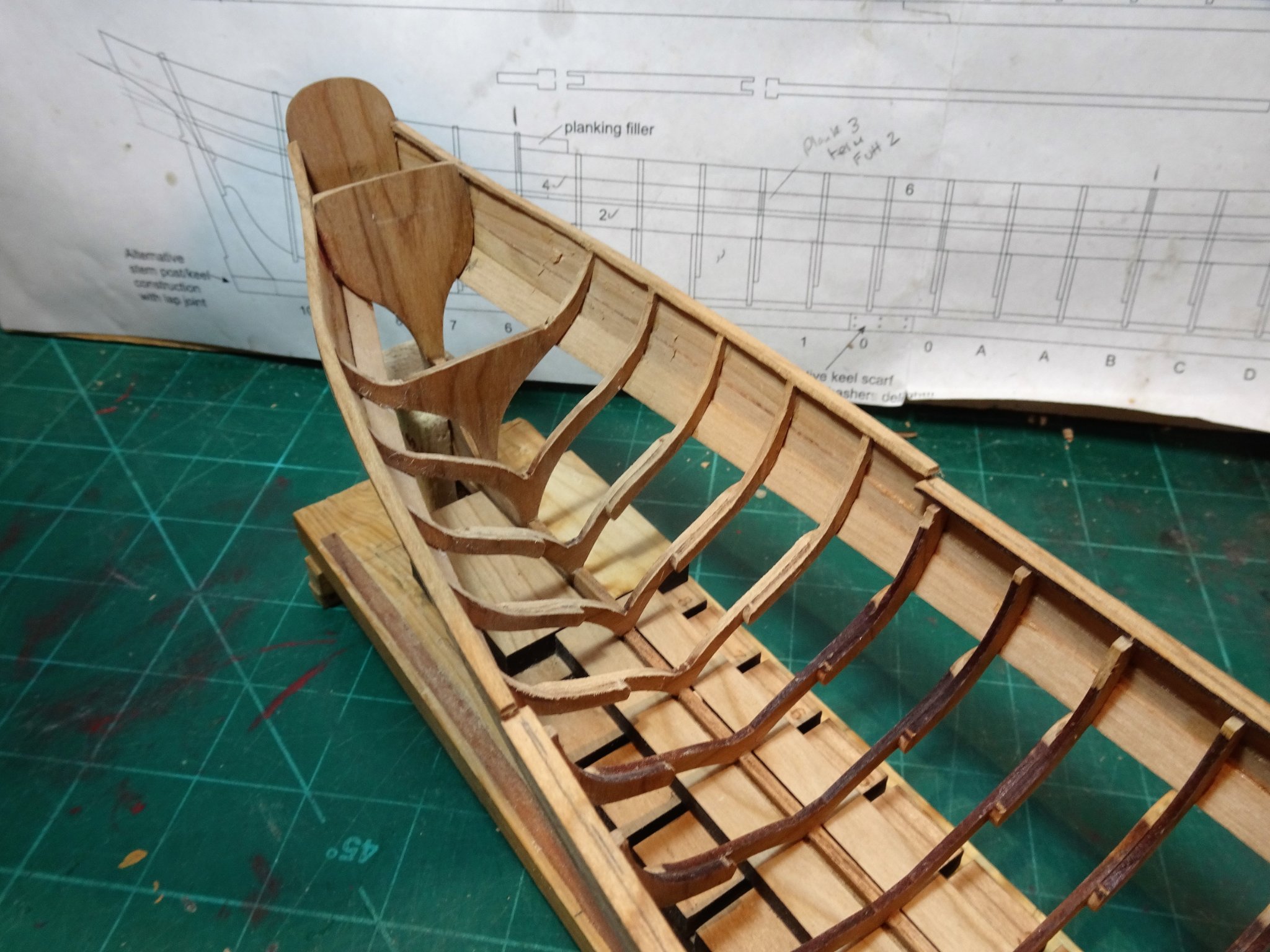
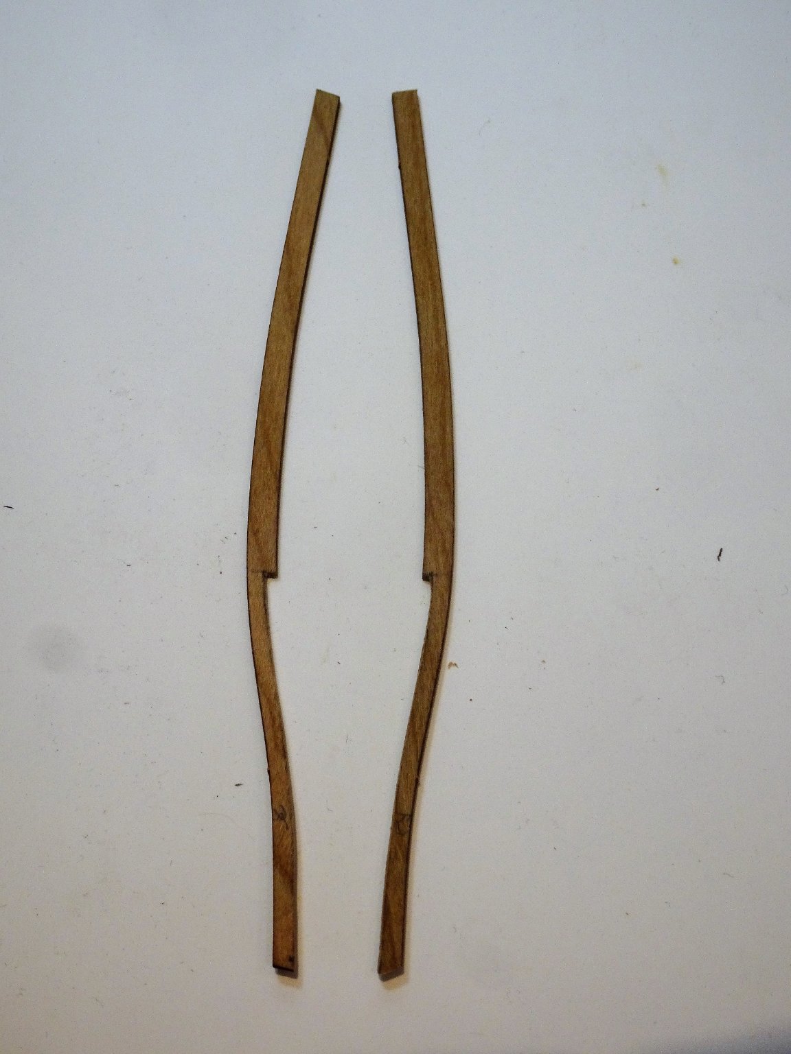
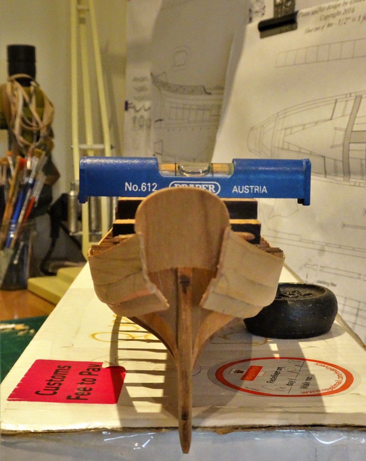
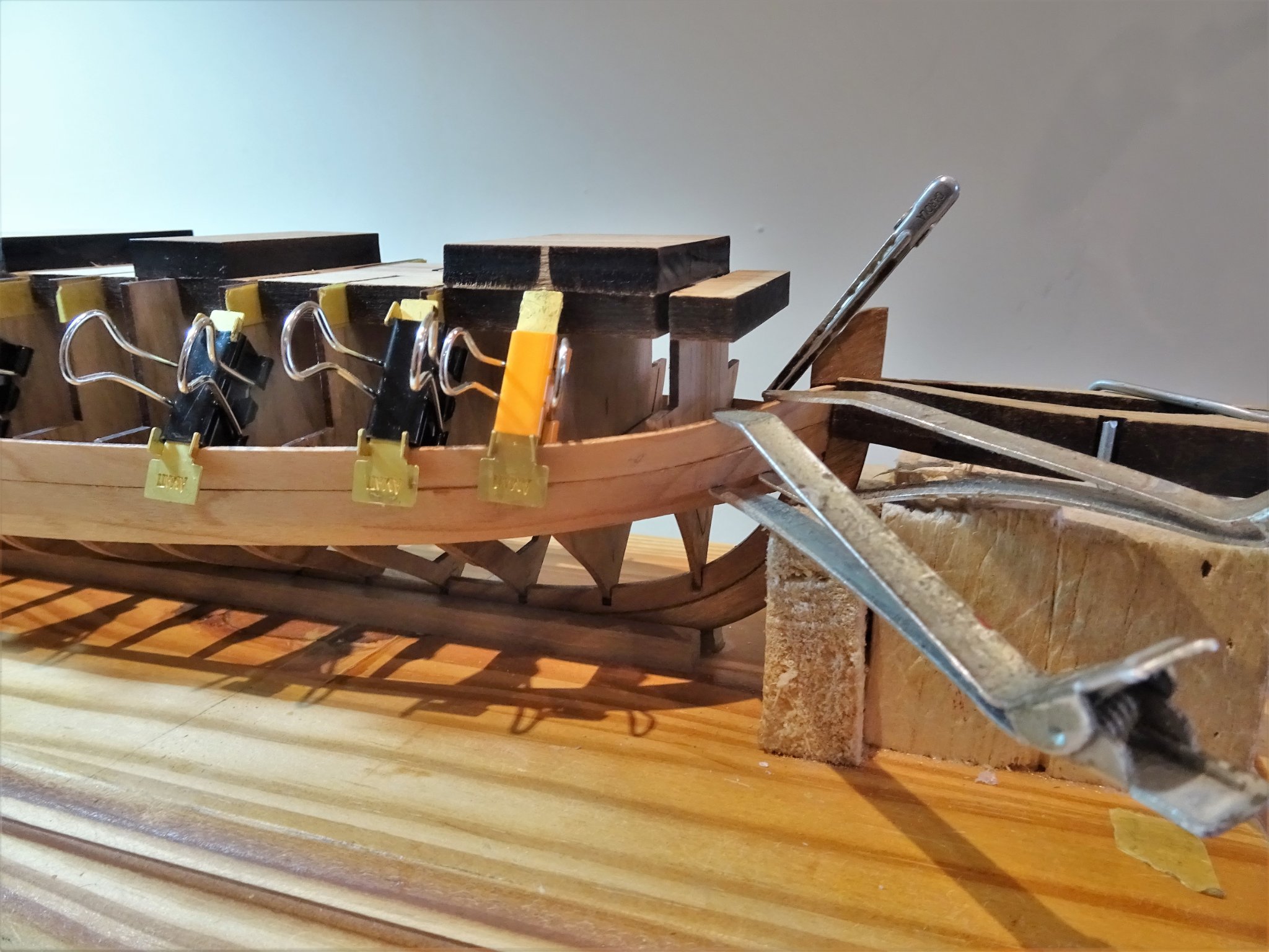
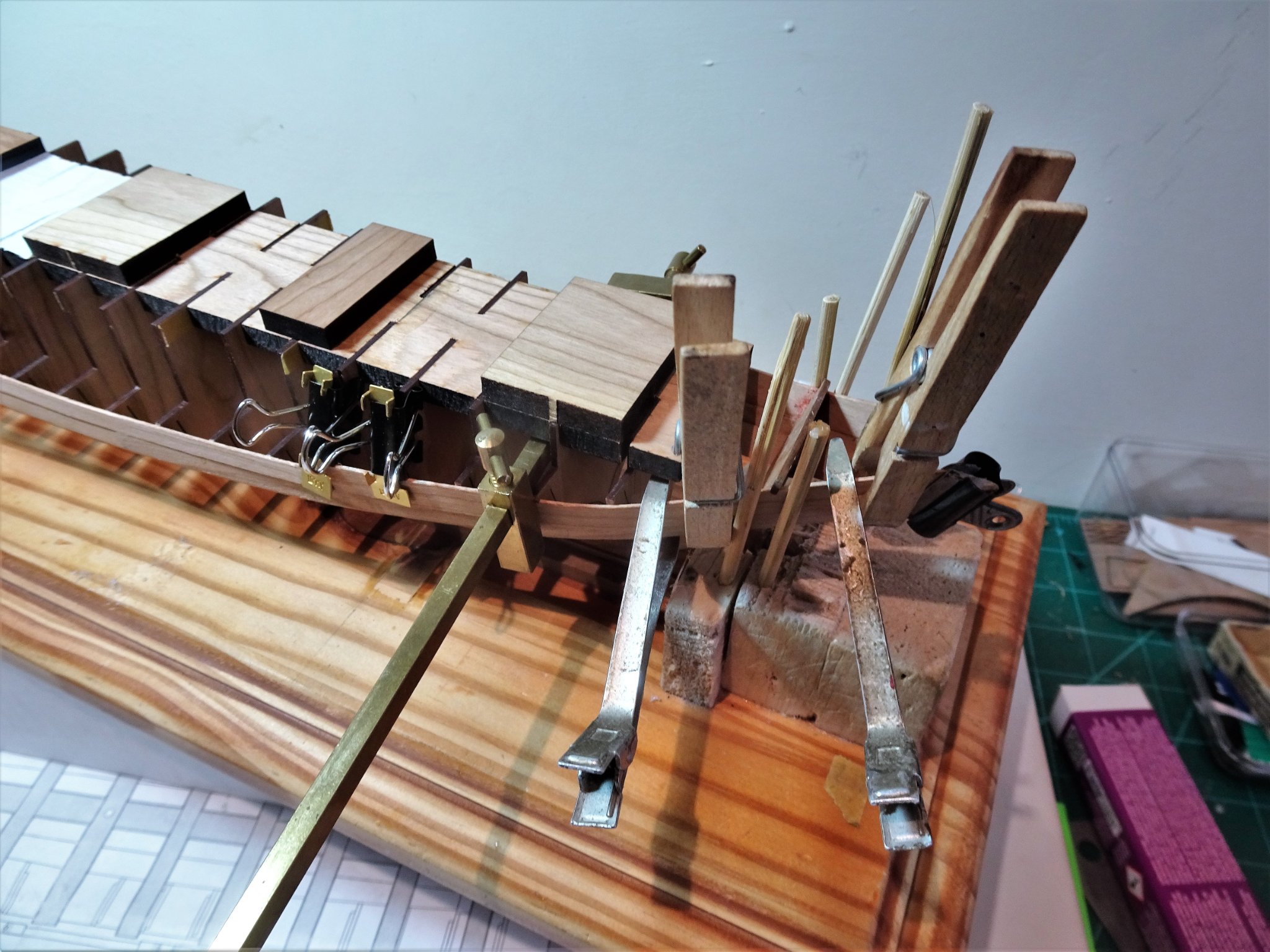
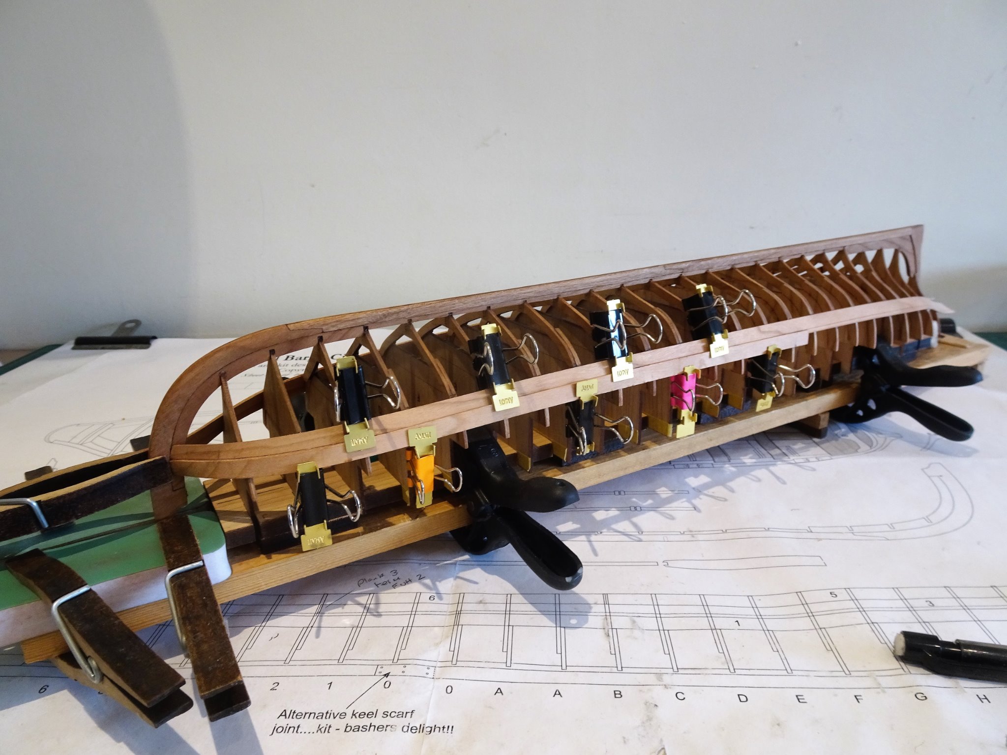
Post Thirteen Cap Rails and frames I can’t say I’m looking forward to the slow and delicate process of adding the cap rails and fining down the frames. The Cap rails are first fitted and then the frames and rails thinned down to achieve a consistent 5/64” width along the entire length of the rail. I scratched my head a little over this. As we in the UK have used the metric system for many years, (Napoleon did at least win this campaign, eventually) for ease of working I need to convert. 5/64” as a decimal = 0.0781 x 25.4 = 1.984mm The finished rail is indicated as a hair less than 3/32” 3/32” as decimal = 0.09375 x 25.4 = 2.38mm I was a little puzzled as the working width seemed less that the finished width, but by less than 0.5mm. I decided to aim for a working width of 2mm. First things first, the frame tops are to be levelled flush with the sheer strake. Chuck is right these took more work than first envisaged. I started with the Starboard Bow rail. This needed a deeper recess at the stem point to allow it to sit at least flush at all points with the planking at the bow on the outboard side. (Probably something to do with my fairing of the bow area.) 1308 Once set, I fitted the Port side rail which was no trouble at all. 1310 The long centre rails were trimmed and fitted next without issues. The final stern strips involve a little more work, bevelling to meet the Flying Transom and notching of the Transom to take the rail. This begs the question how much of a notch? Given that the finished rail should be 5/64” or 2mm in my world. I opted to make the notch 2mm including the thickness of the Sheer strake. I pre-cut the stern rail from the Flying Transom forward to Frame 10 to a 2mm profile. 1311(2) The rails needed one further tweak, a slight edge bend to follow the inward curve as the rail meets the Transom. Here the lower Starboard rail has been subjected to the treatment. 1314 The ‘tweaked’ stern rails. 1321 Stern Rails in place, the pre thinned area aft of Frame 10 will eventually be continued along allowing for a flare at the bow. 1319(2) 1326(2) 1320(2) Sanding down of the rails to be flush with the exterior planking is mostly done, a little tweaking here and there. I now need to work out my approach to the internal fairing of the frames. B.E. 28/03/21

.thumb.JPG.725c5f09cee6eaeabb301a032a9b9050.JPG)
.thumb.JPG.a83dee318e17dc4f233bd69b53b07ecd.JPG)
.thumb.JPG.5429db6425dcd1132d3bbd3a3f371e8d.JPG)
.thumb.JPG.885c544287a2c81433e5d27131d20e87.JPG)
- 185 replies
-
- 9
-
-
- queen anne barge
- Syren Ship Model Company
- (and 1 more)
-
Thank you, Bruce, and Rusty. @ Rusty – I only hope I can match your standard of rail/frame completion. Useful tips on your log, I like your use of a width gauge for the rails. Did you first start by thinning the inboard rails, or the frames? It seems to me that the rails would be sanded horizontally along the grain, and the frames vertically. Regards, B.E.
- 185 replies
-
- 2
-
-
- queen anne barge
- Syren Ship Model Company
- (and 1 more)
-
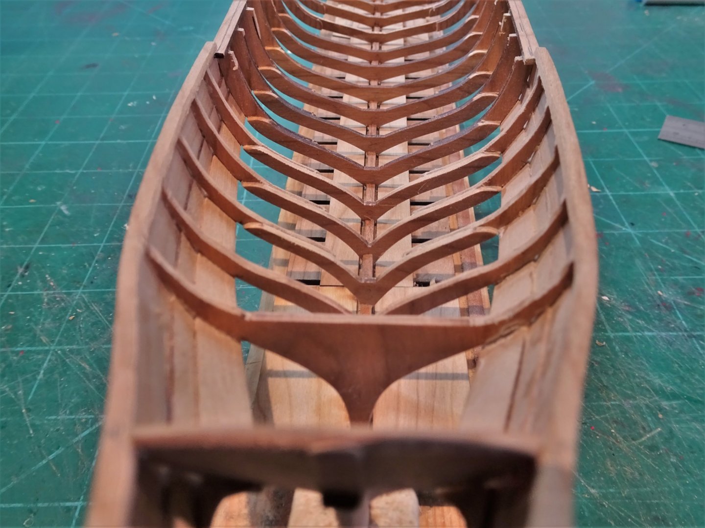
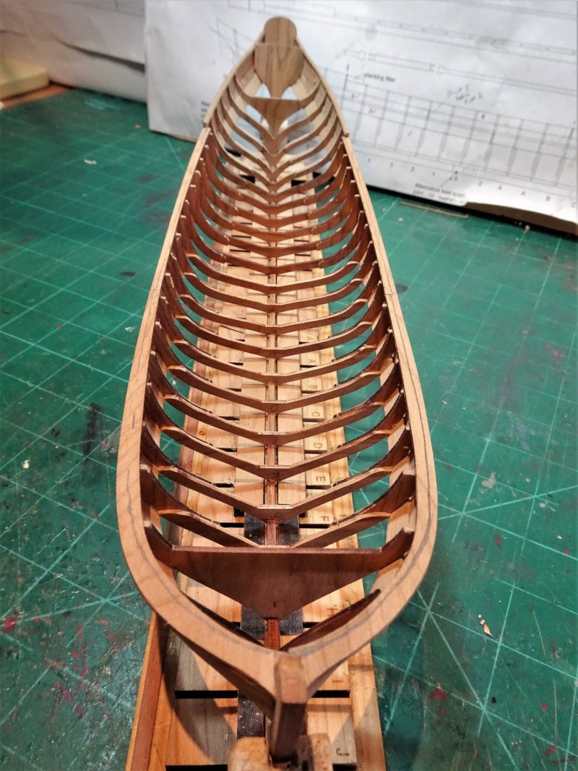
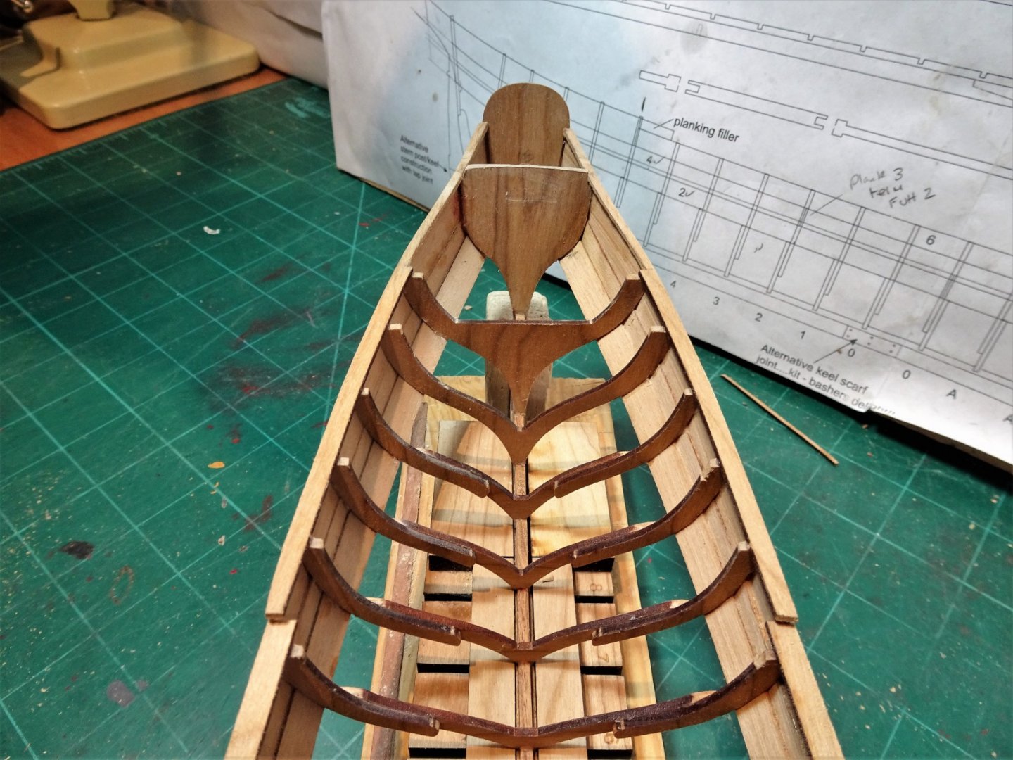
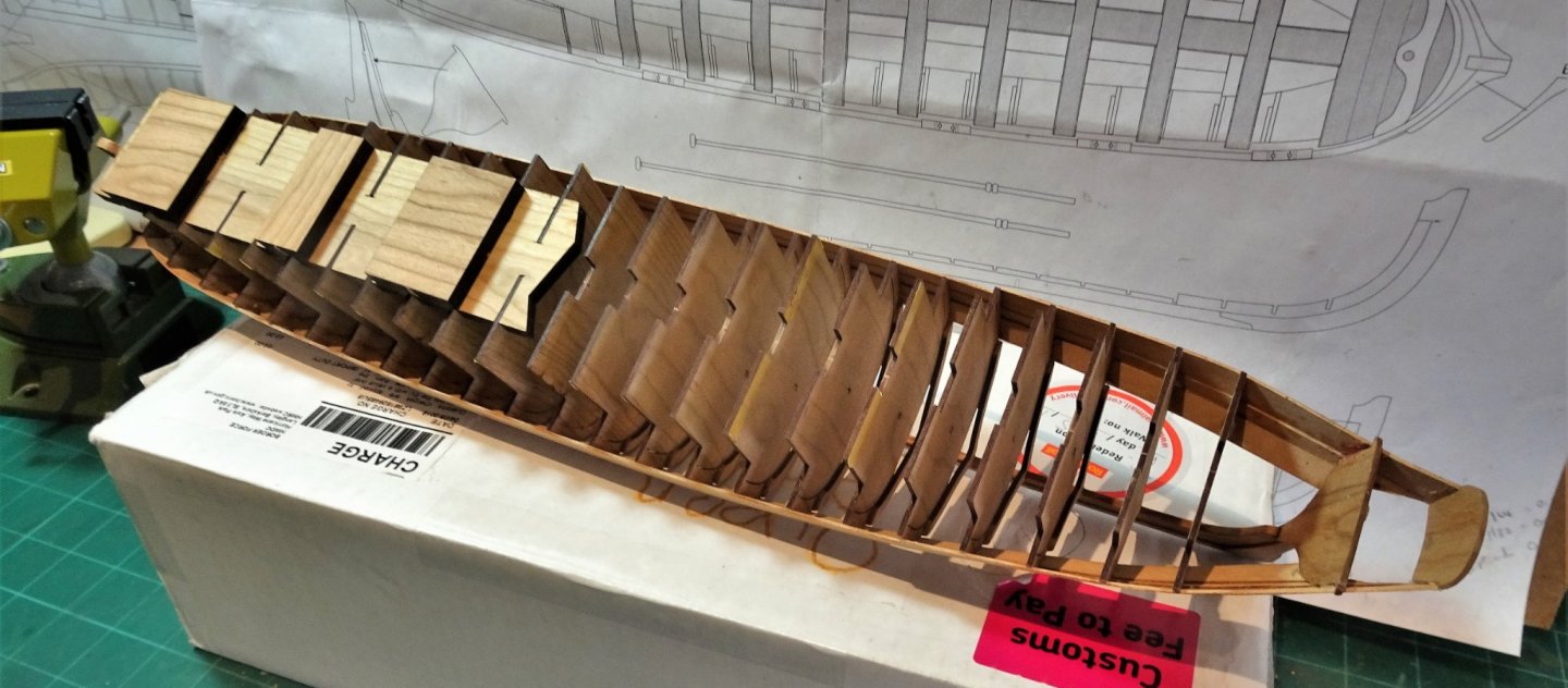
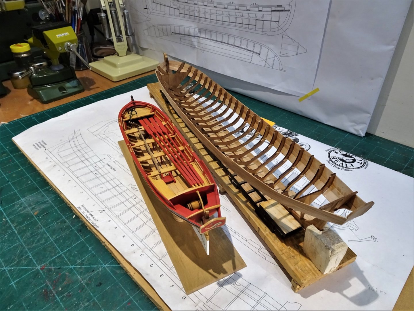
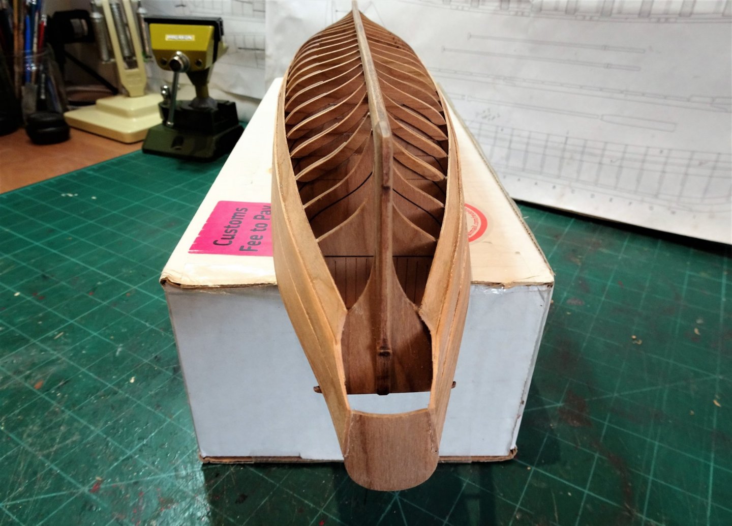
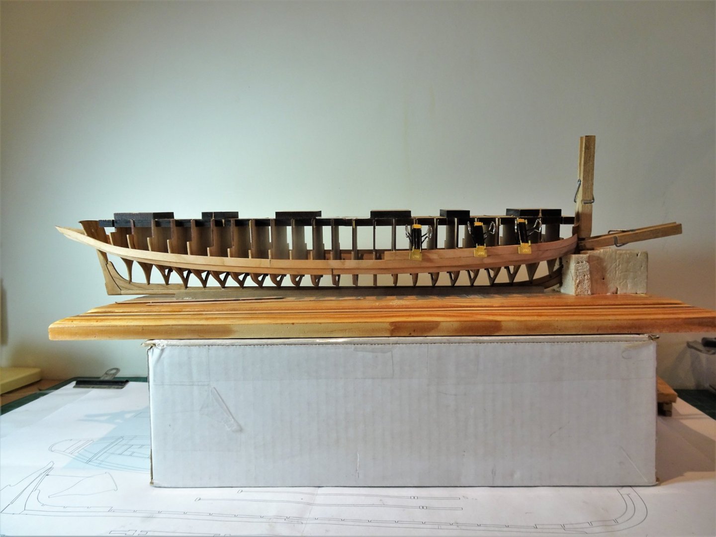
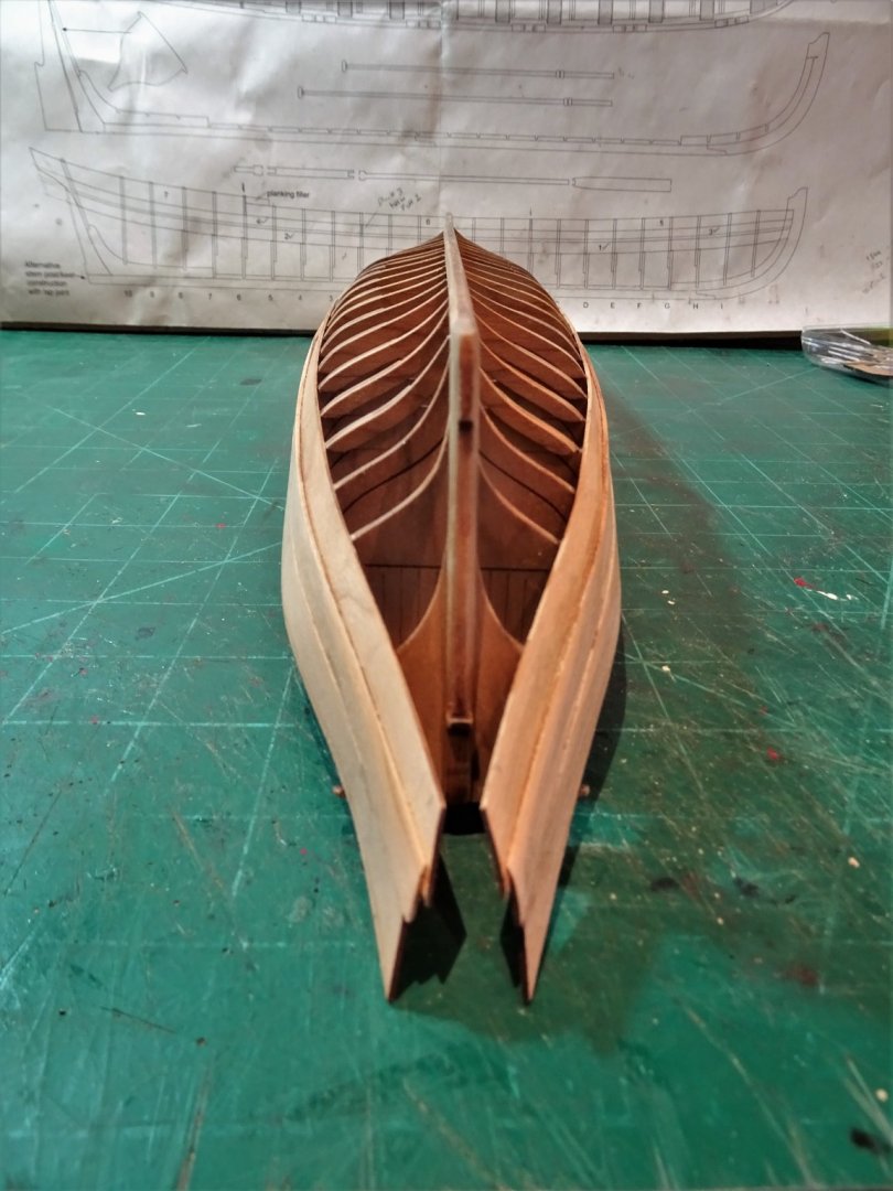
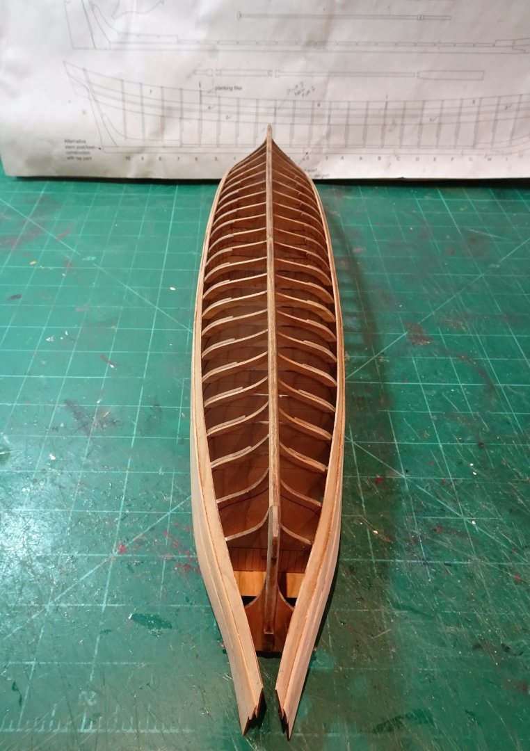
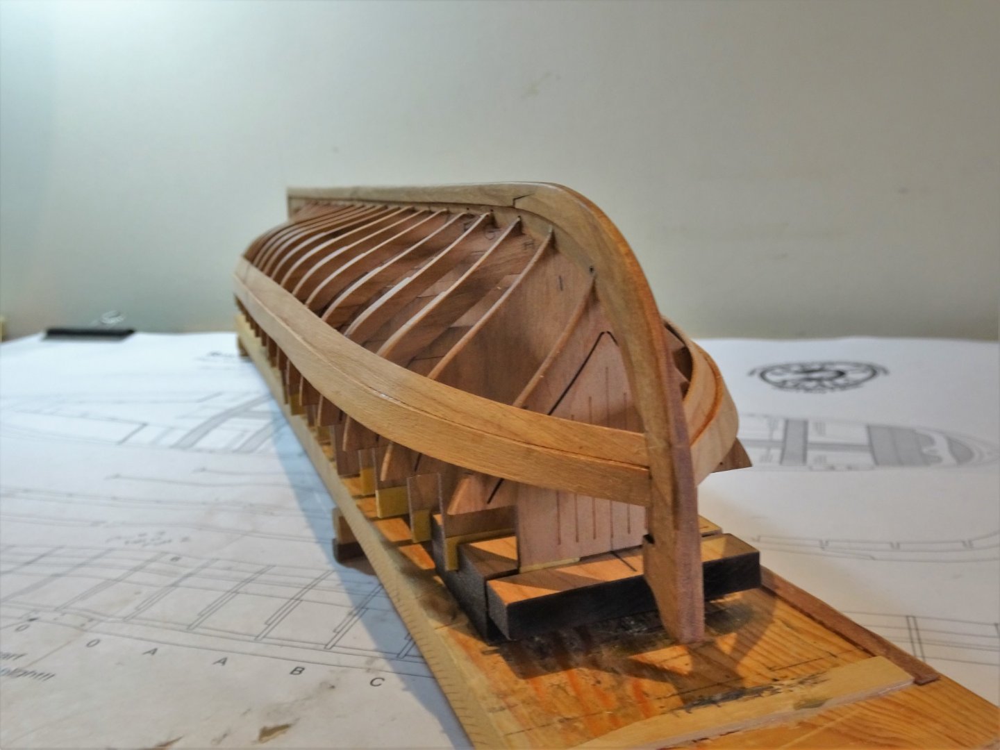
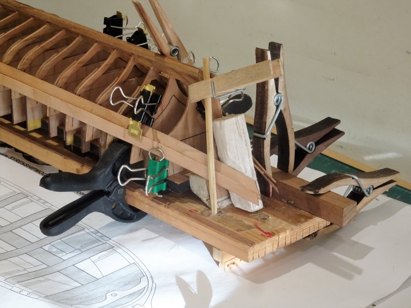
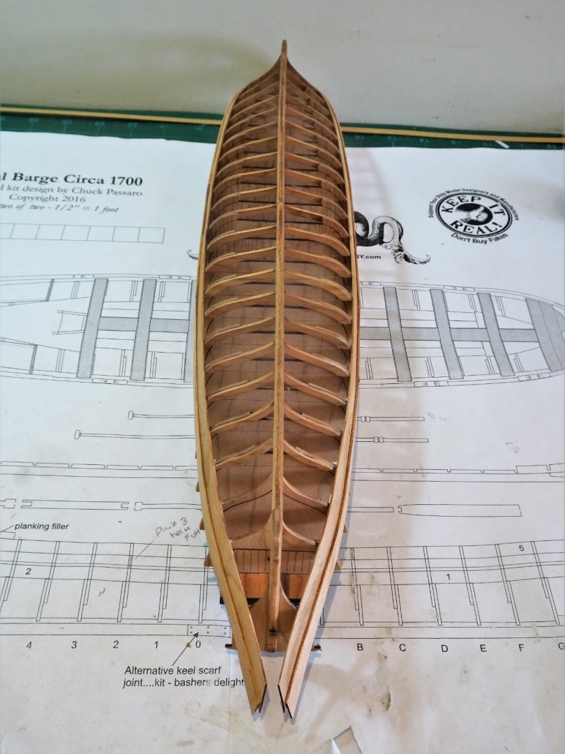
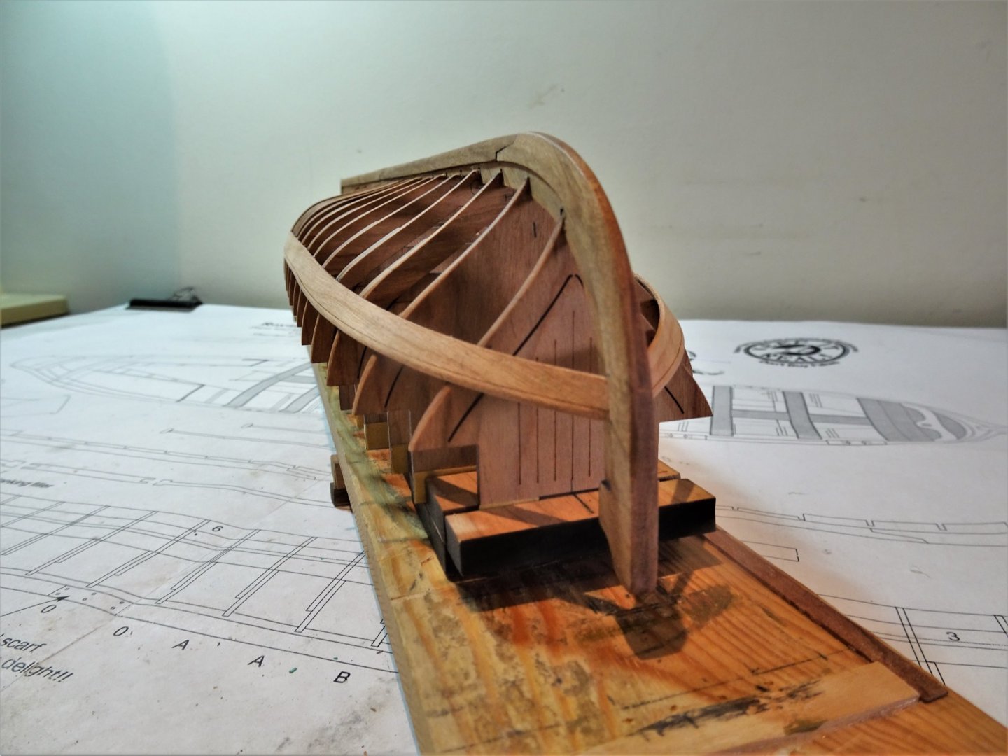
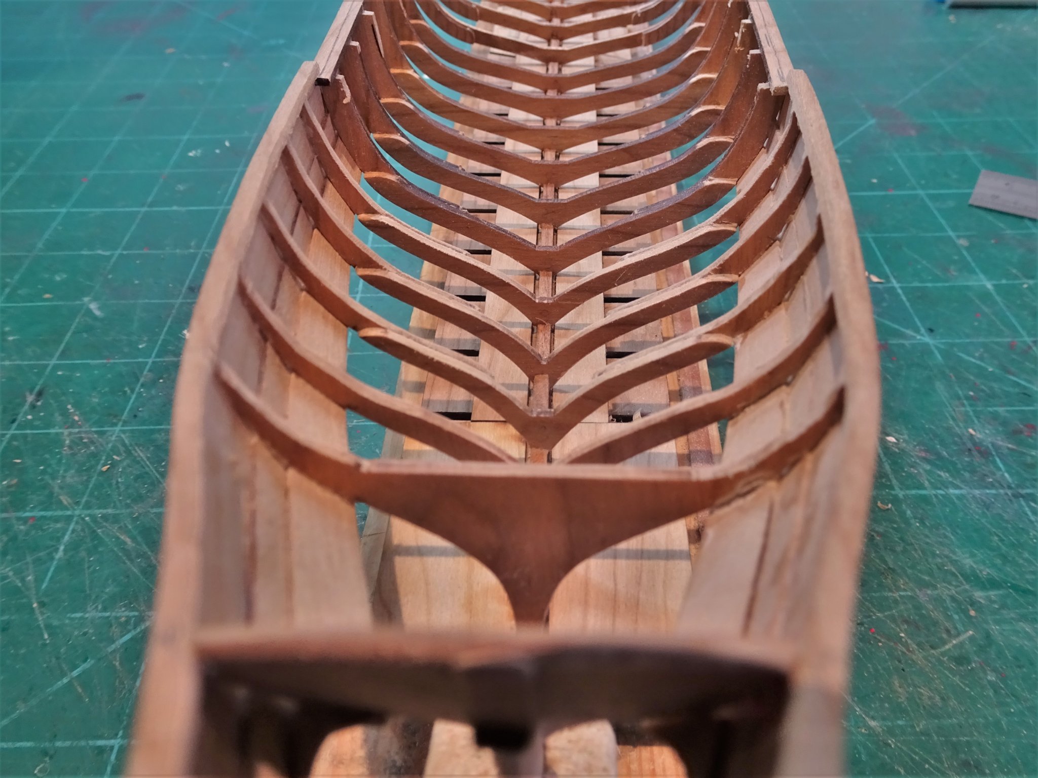
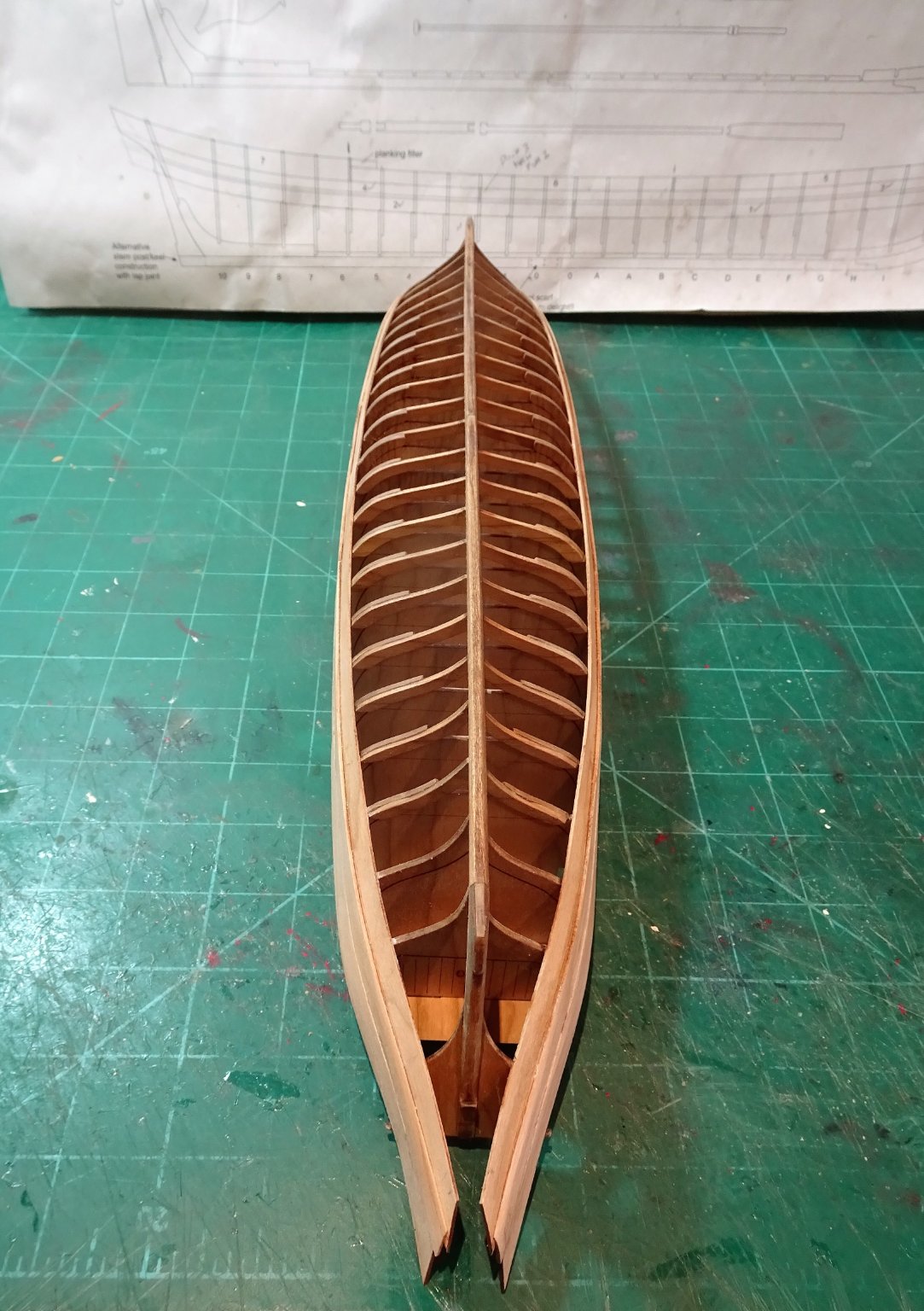
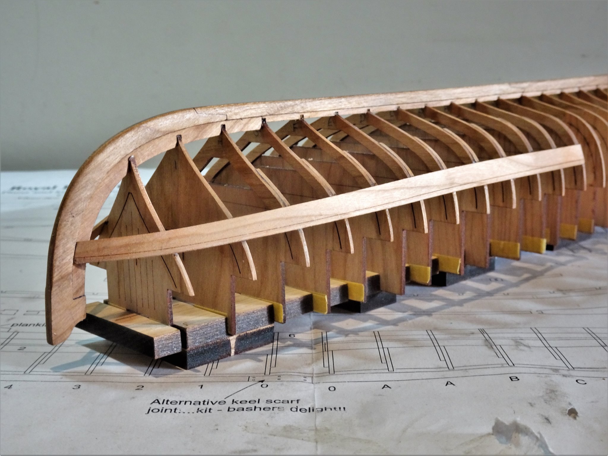
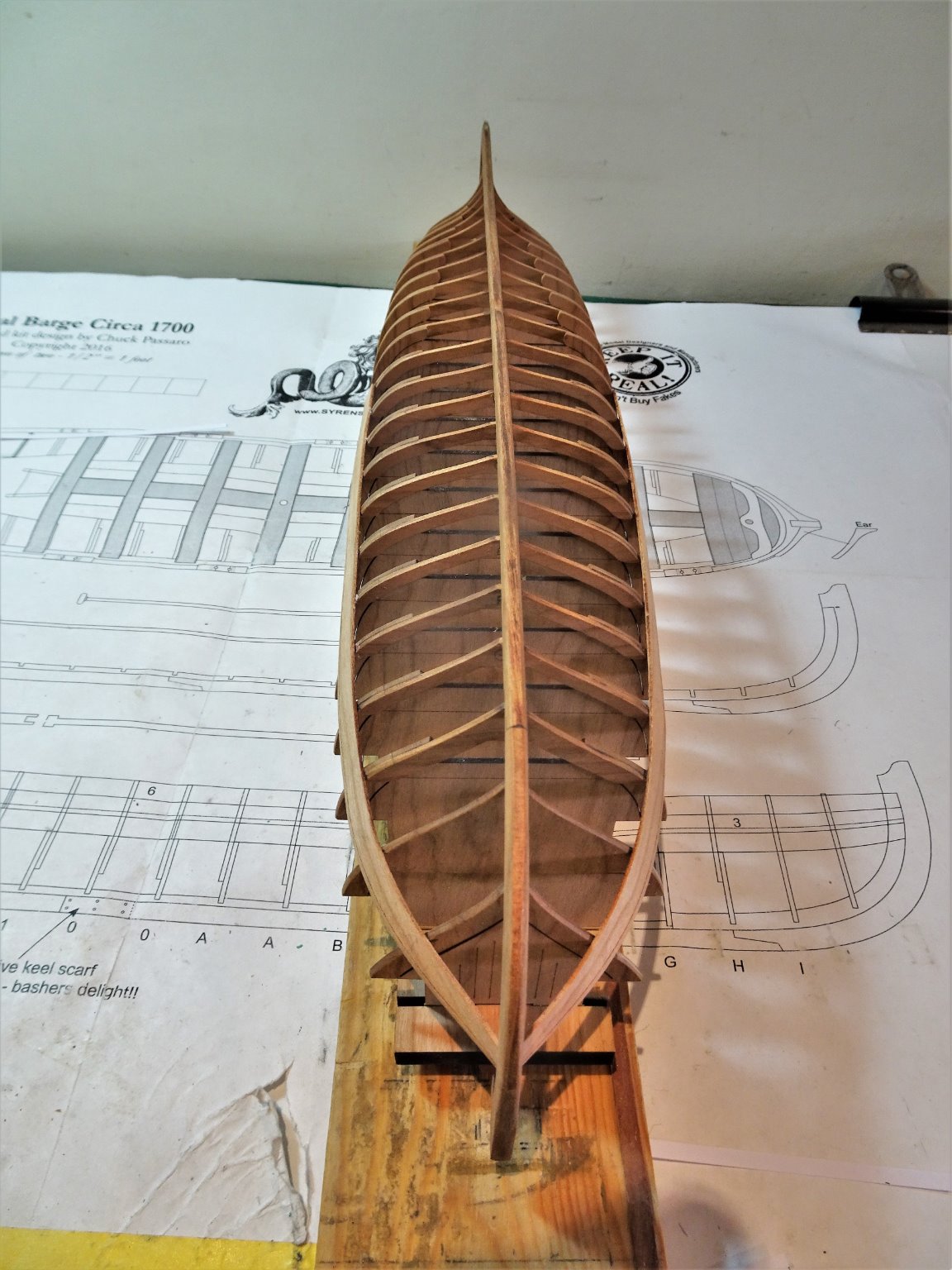
Post Twelve A Barge emerges. A point in the build that I suspect many builders are pleased to reach. The hull is removed from its building board. I took this slowly and carefully as advised by Chuck, and it didn’t prove too onerous. I now have my first sight of the model the right way up unencumbered by the board. 1235 Front part of the board removed, so far, so good. At this point I was tempted to add the Garboard strake as shown in Chuck Seiler’s build, which would also no doubt help to counter any tendency for the hull to hog, given the length and fineness of the keel. I rather liked to look of it, but I also liked the view of the deadwood at the stern which would be obscured by the Garboard strake. Decisions, decisions, but in the end I opted for the original Chuck presentation. 1238(2) I modified the building board for the second stage of the build as suggested in the instructions. Stem and stern post supports are necessary to hold the hull secure. 1242(2) I am a big fan of Balsa blocks to support models whilst working. They are endlessly re-worked to suit each new project. 1244(2) The barge is now held firmly in place for me to begin the business of frame centre removal. 1246(2) For this delicate operation I am using an etched fine-toothed scalpel saw. 1286(2) The whole process went very well, a few of the frames broke away from the planking but were easily re-glued, and there were no breaks in the frames themselves. 1281(2) Once cut, the centres came away easily using a gentle rocking motion. The discarded centres will no doubt come in for other projects. My covid hairstyle continues to develop, and still several weeks away from a barber, but who needs a barber when you’re busy building a Barge. 1278 With all the centres removed I can now sight along the hull and clearly see whether my fitting of the Transoms looks right. 1287(2) It looks ok to my eye, but stare at something too long and………. 1290(2) A chance to compare this 36’ Royal Barge to my 21’ Pinnace, both at 1:24 scale. 1292(2) 1295 1298(2) Four weeks fairly steady work to reach this point and I have what looks like a Barge in Frame. Back under its cover for the Pinnace, and onto what Chuck describes as the most delicate stage of the build. I suspect progress is about to slow down. B.E. 24/03/21
.thumb.JPG.fd0fb12b32dc93a7debcc7fd11bb254a.JPG)
.thumb.JPG.8fe17b64da821d50c059043c25a6cc91.JPG)
.thumb.JPG.48edcc904c47ddef9f5a20ebbfec06ca.JPG)
.thumb.JPG.9386866c570bd7f63dbe34b58b6e7ca2.JPG)

.thumb.JPG.6b515daf9d85a12be2025f65bf2416d0.JPG)
.thumb.JPG.fdbb15ea1dc9e16d9137e61ec49b0781.JPG)
.thumb.JPG.c3da95716995b60d306327bc00631eae.JPG)
.thumb.JPG.7fde9840facc7532bcf794115675f26b.JPG)
.thumb.JPG.52340628385d6a3b5dfff95395e1b8ed.JPG)
.thumb.JPG.eee24c52e5afcdb527b799326897d4e9.JPG)
- 185 replies
-
- 16
-
-
- queen anne barge
- Syren Ship Model Company
- (and 1 more)
-
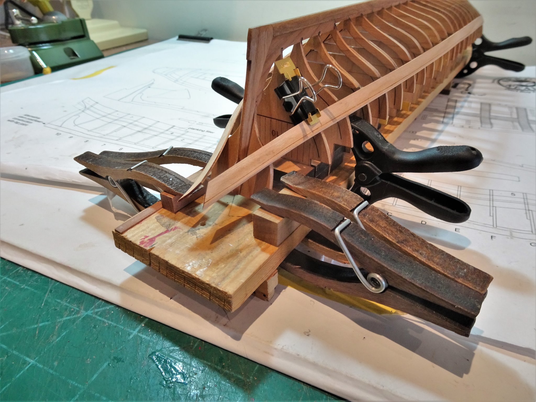
Thank you, Chuck, Glenn, Michael, and Kirill, and for the ‘likes’. @ Glenn – Clamping is such an important part of ship modelling, I don’t think you can have too many clamps, and getting inventive with methods is part of the skill set. @ Kirill – I do use ca gel but usually only in those areas where clamping is difficult or instant grab is necessary. I use pva in preference as it is kinder to the wood (and me) and it doesn’t mark the surface of timber or make it brittle, as does ca. The pva I use is a high quality non waterproof glue that grabs in around 5 minutes, unwanted spread is easily cleaned up with a paintbrush dipped in water, and water is used to de-bond the glue if necessary. The main thing I would use ca for is applying copper plates to hulls. Bonding other metal items, where I would have previously used ca I now silver solder where possible. Regards, B.E.
- 185 replies
-
- 2
-
-
- queen anne barge
- Syren Ship Model Company
- (and 1 more)
-
All turned out very well Richard, this is the point in a build where the fun part starts for me. B.E.
-
Thanks Peter, an oldie but a goodie as they say, but still a model that can be made a lot of. I think the plastic lion is ok and if treated today with artist oils could look really good. I'm glad they have replaced those plastic blocks and deadeyes, and there is so much stuff out there now to enhance models. I was forty years too early with my attempt. Cheers, B.E.
- 5 replies
-
- 1
-
-
- Norske Love
- Billing Boats
- (and 1 more)
-
Liking what I see Phill 👍 B.E.
-
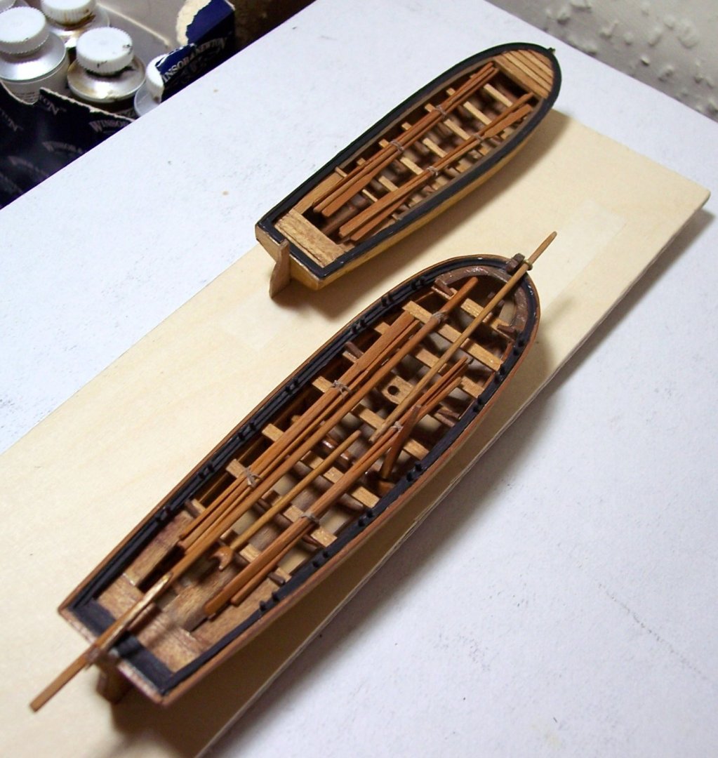
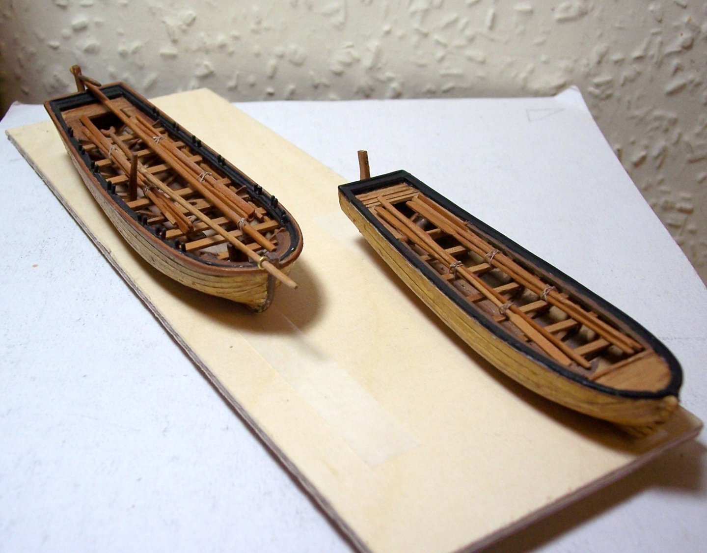
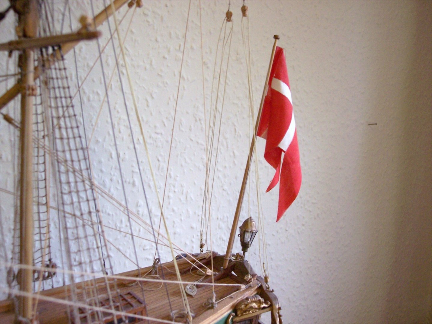
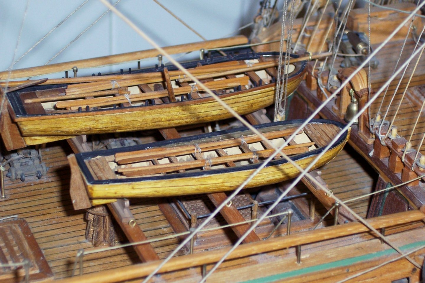
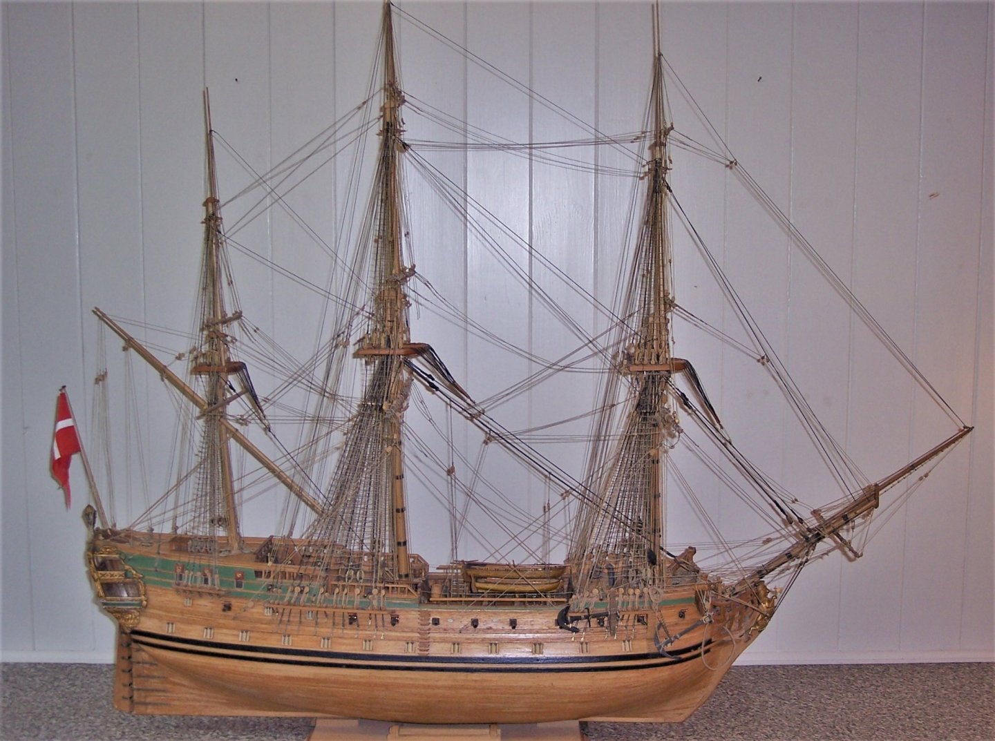
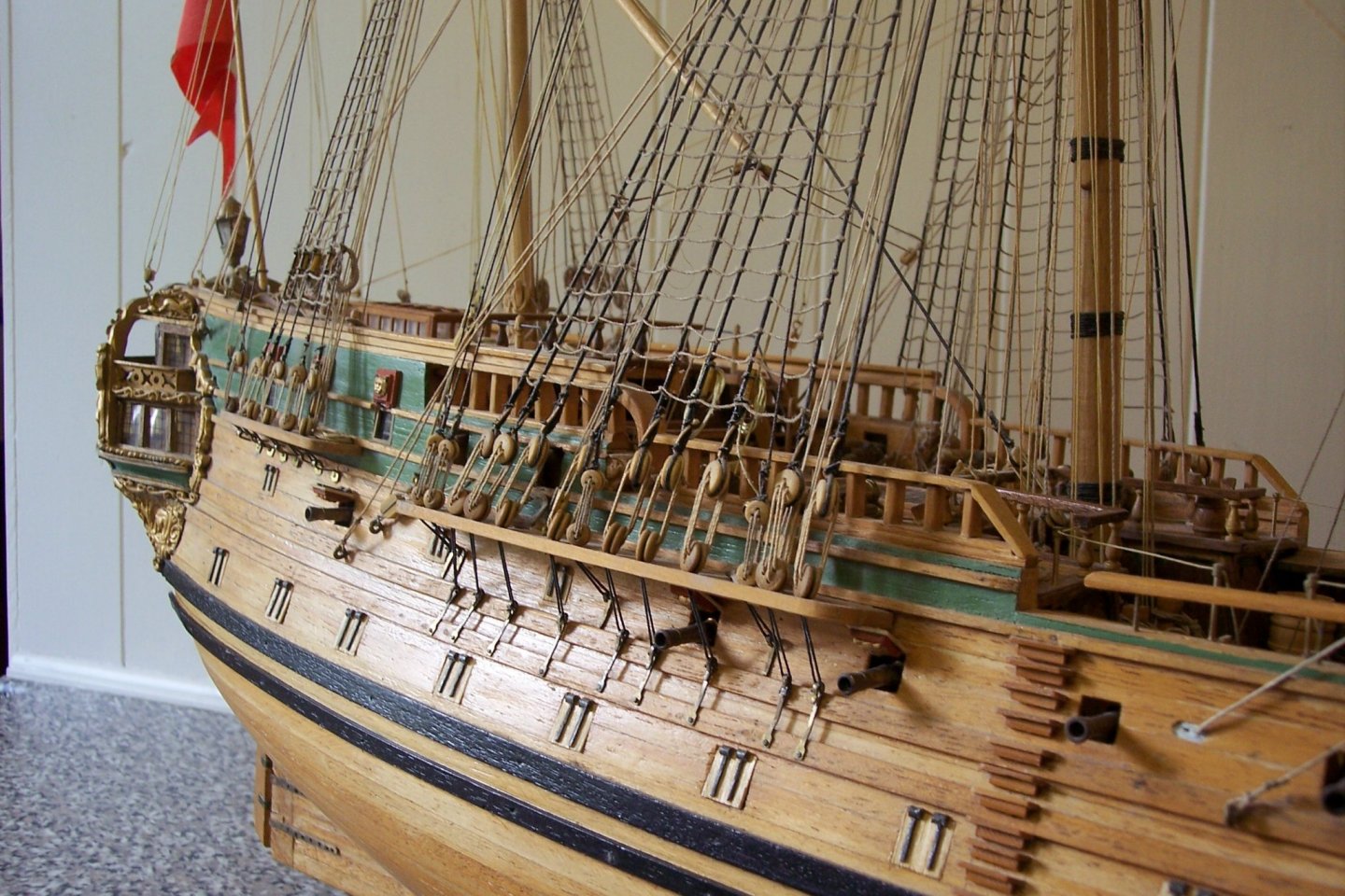
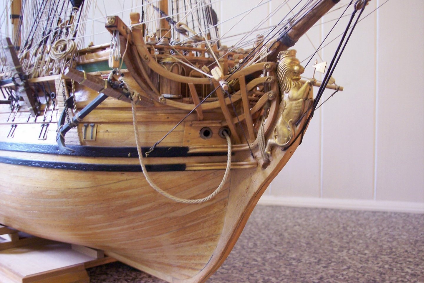
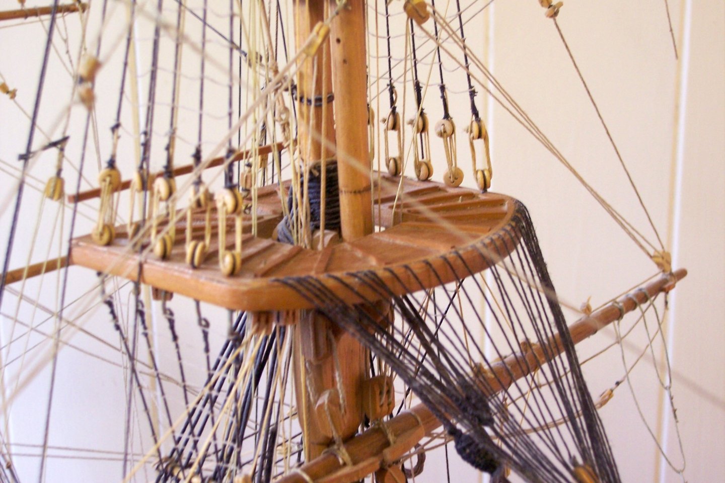
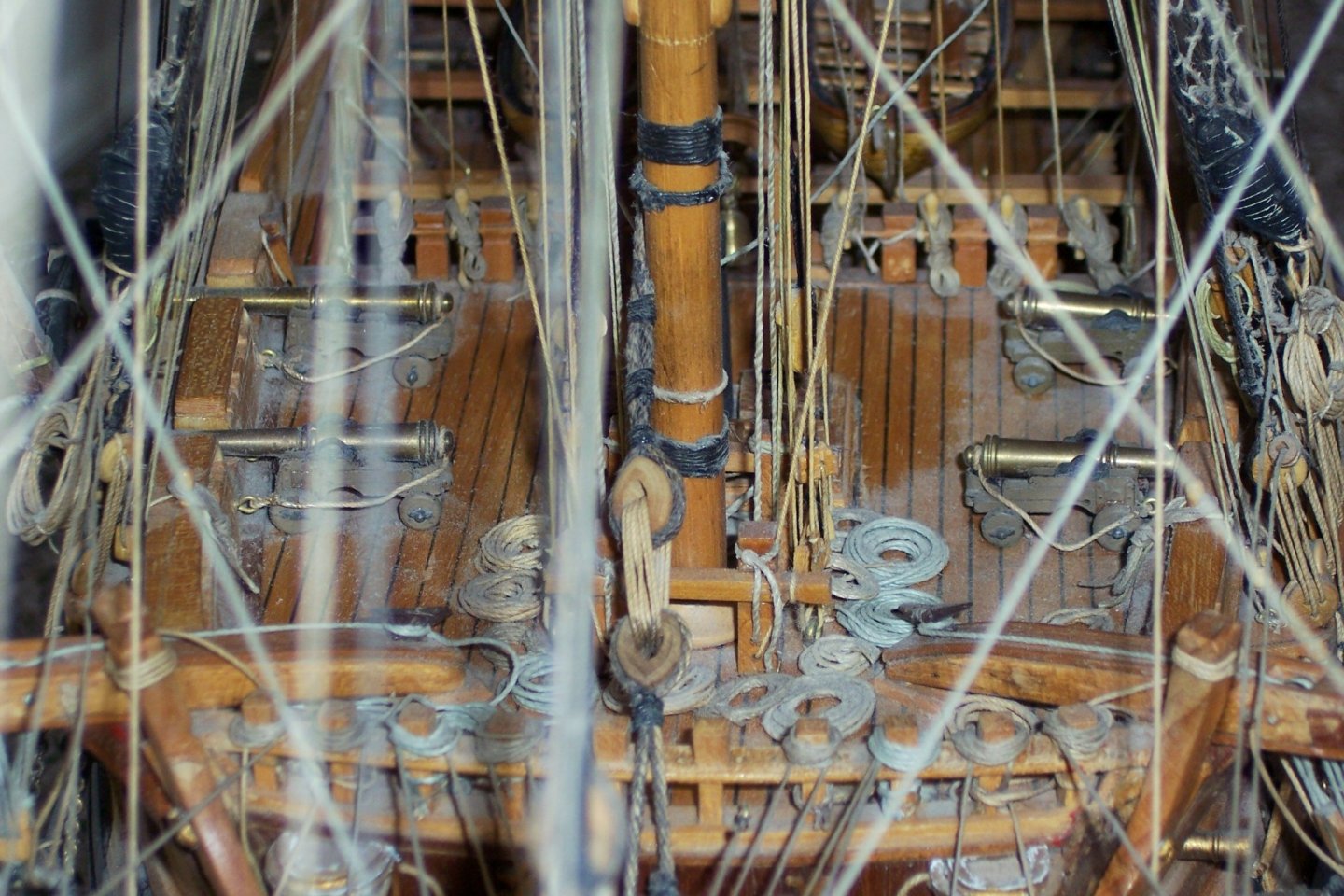
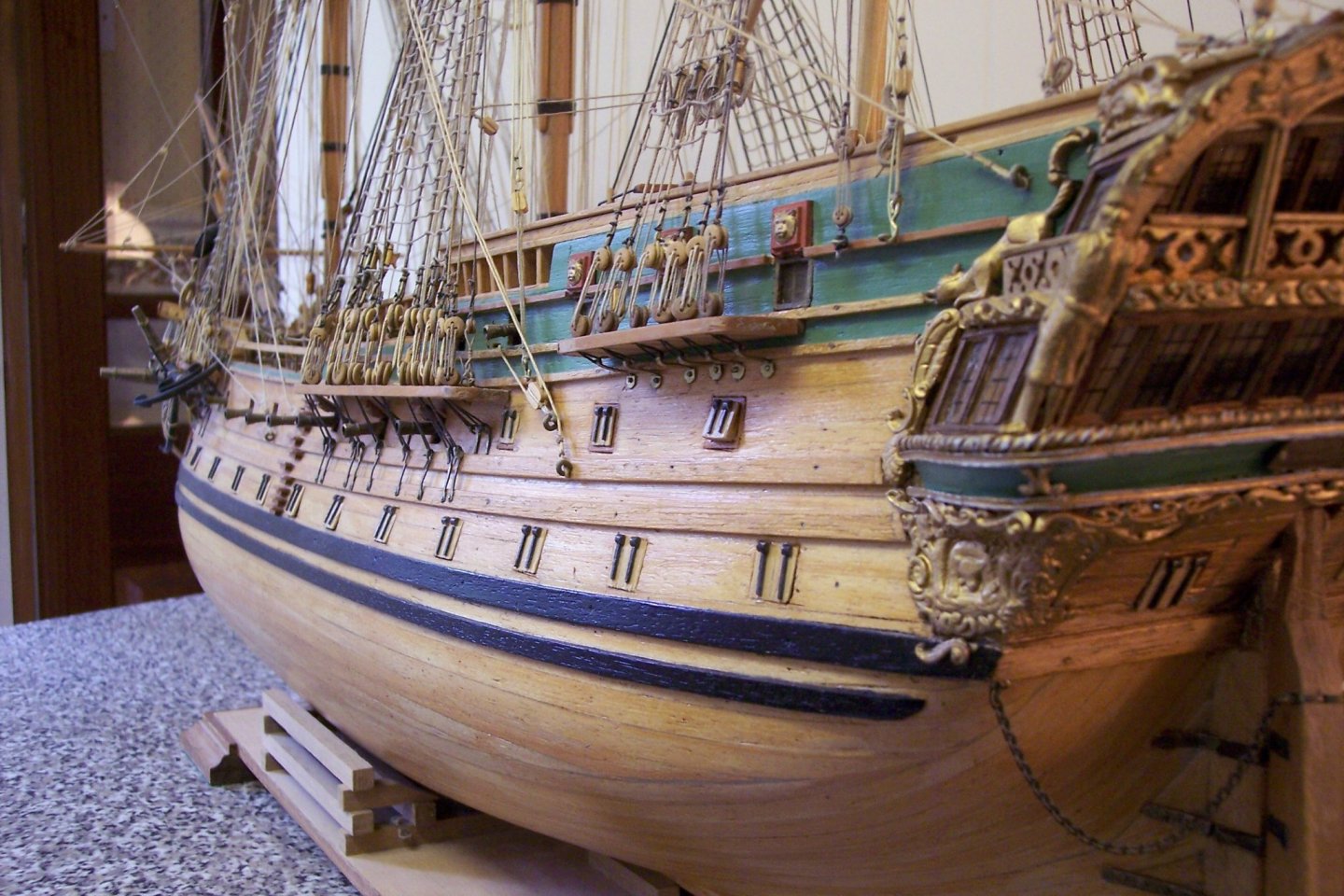
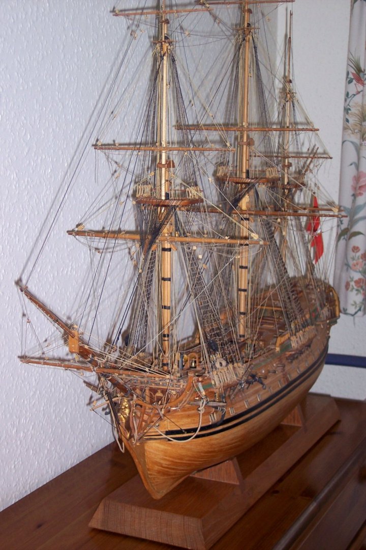
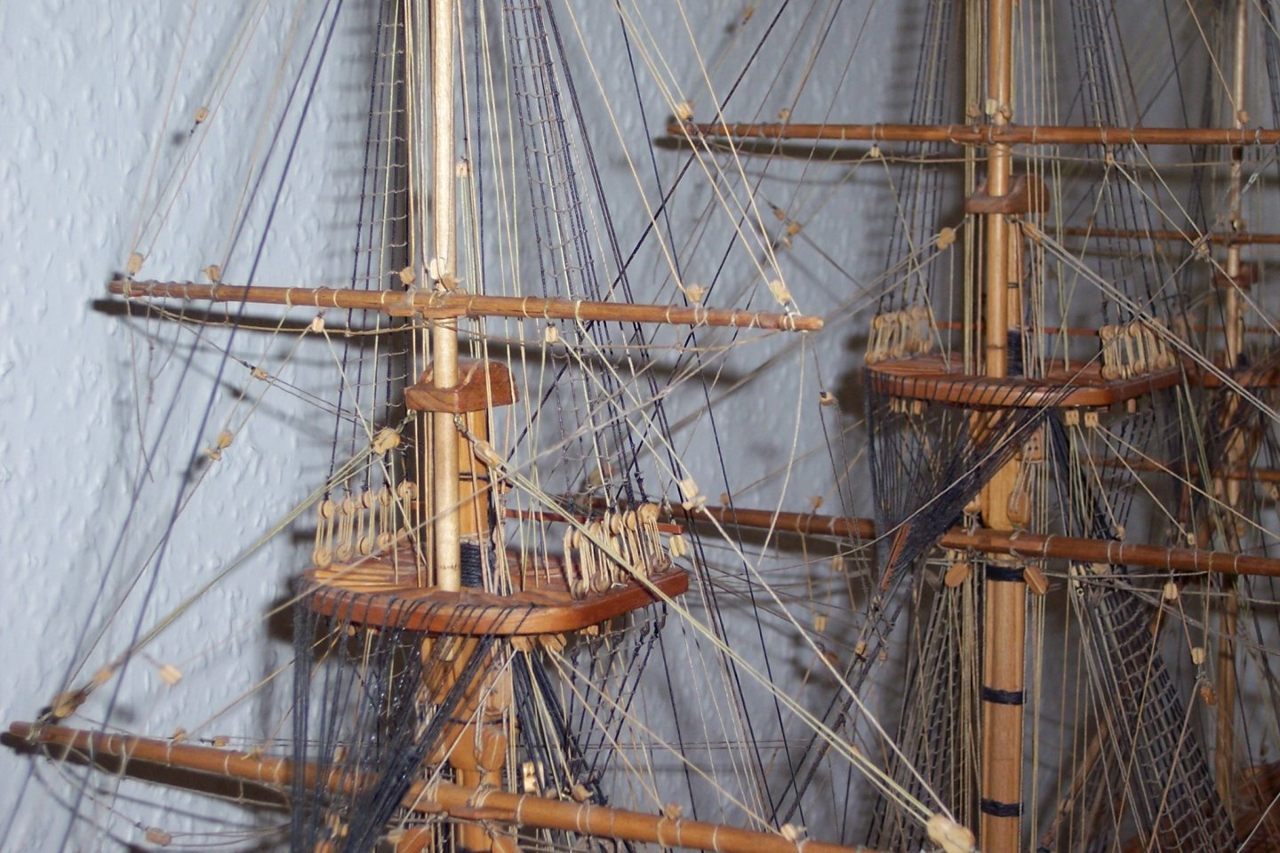
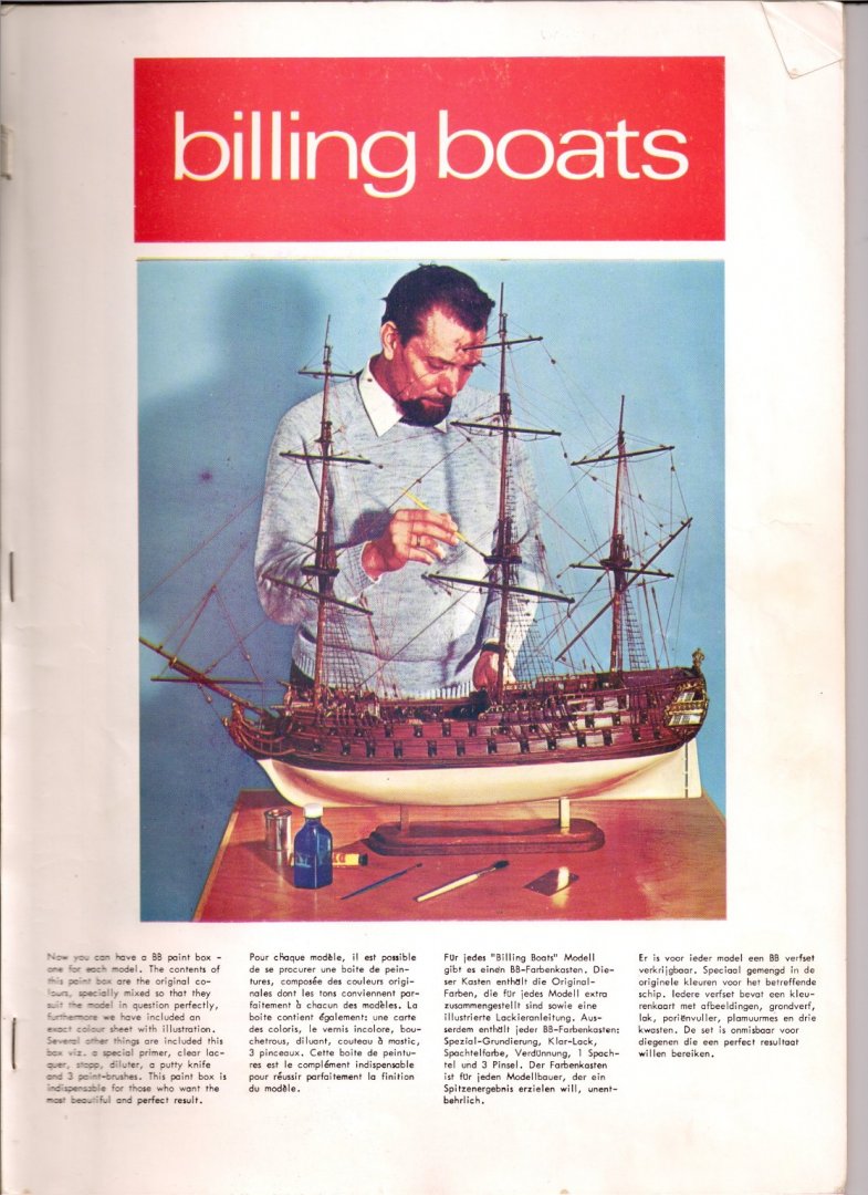
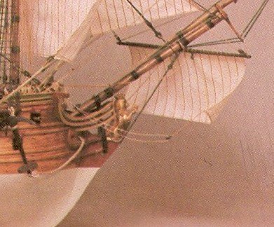
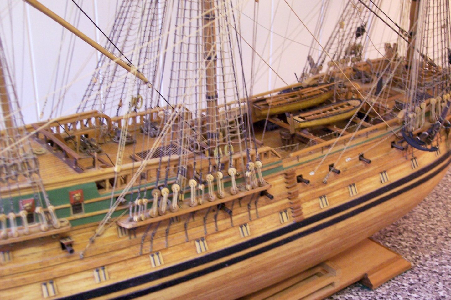
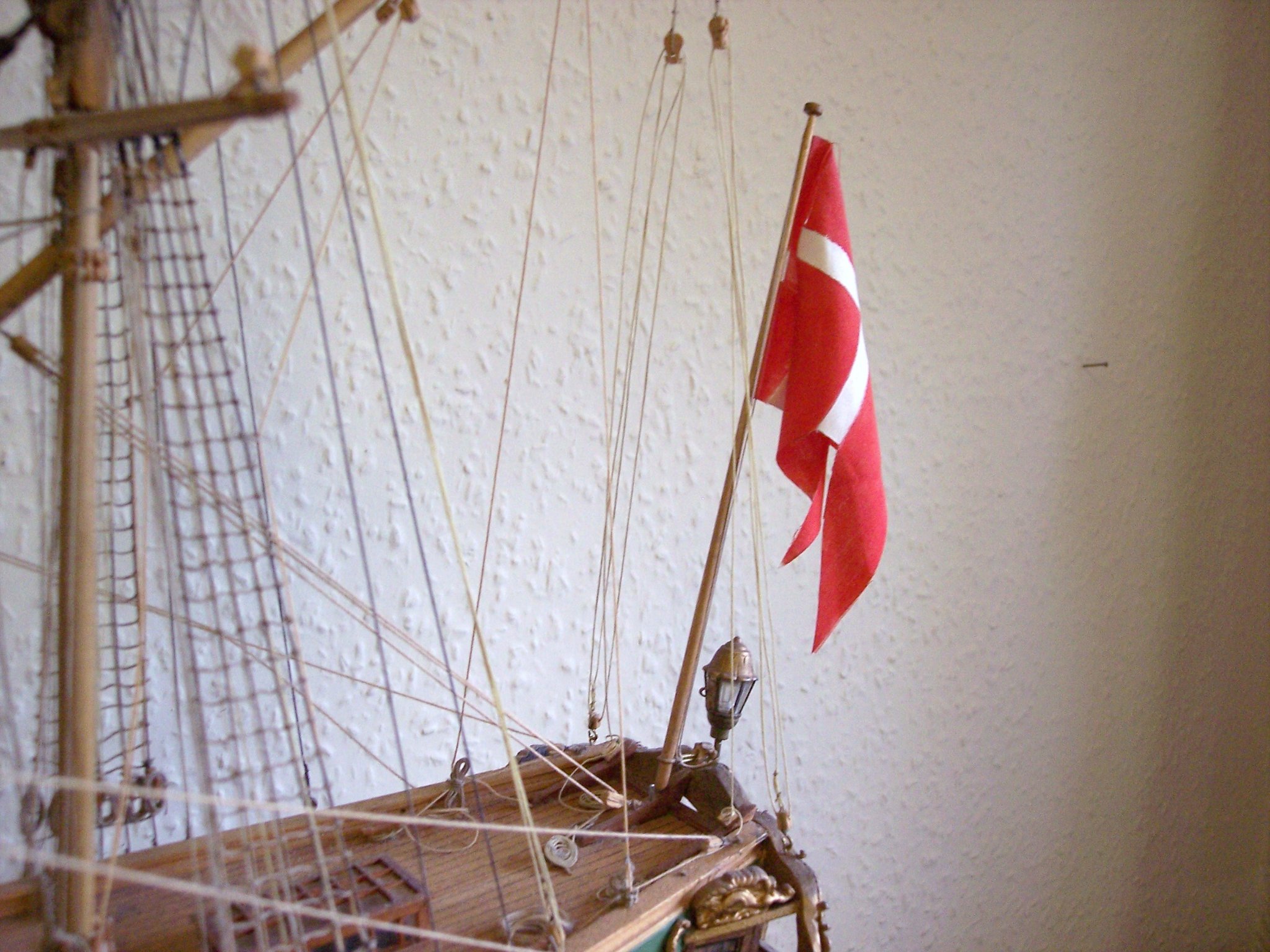
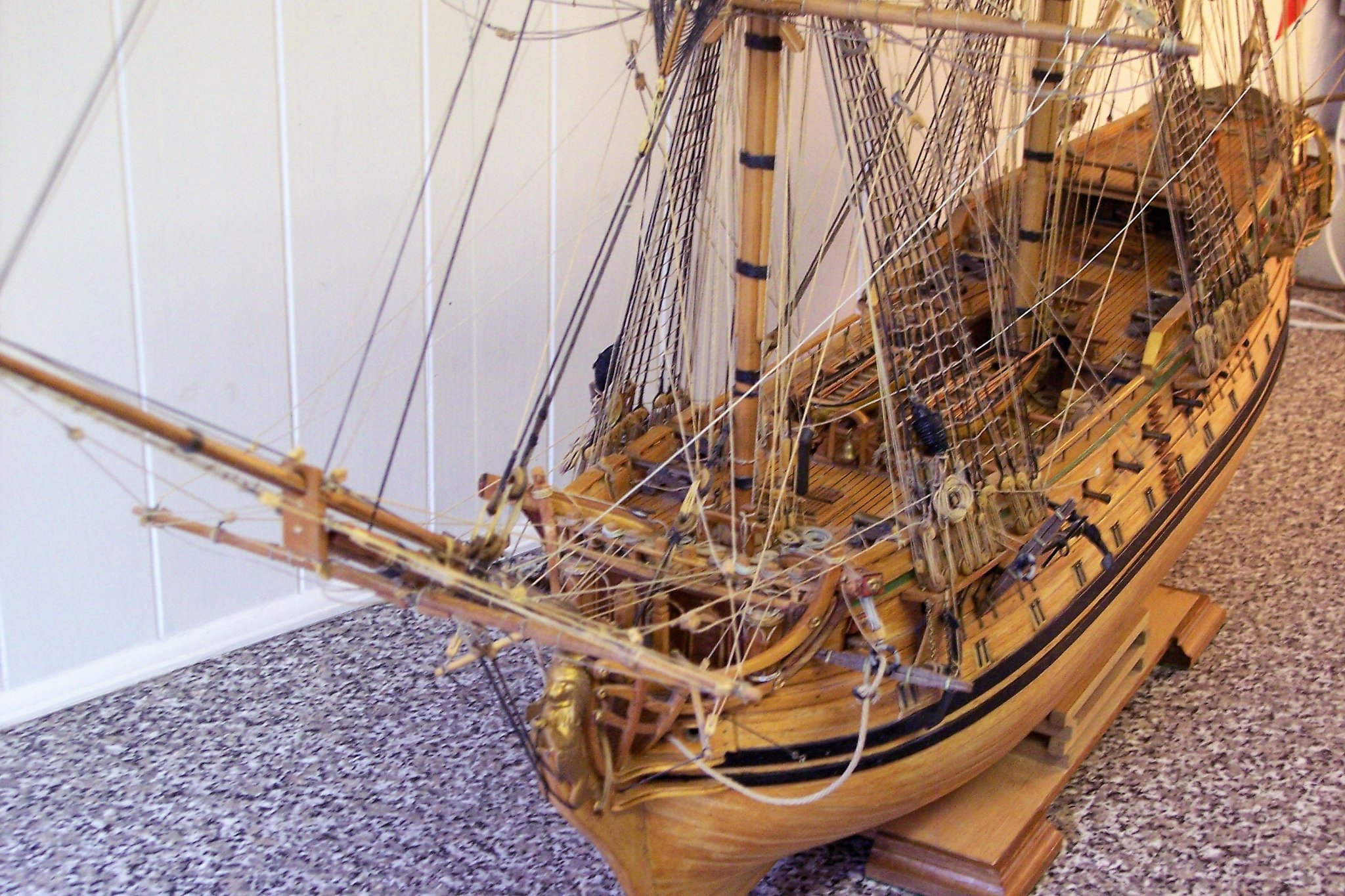
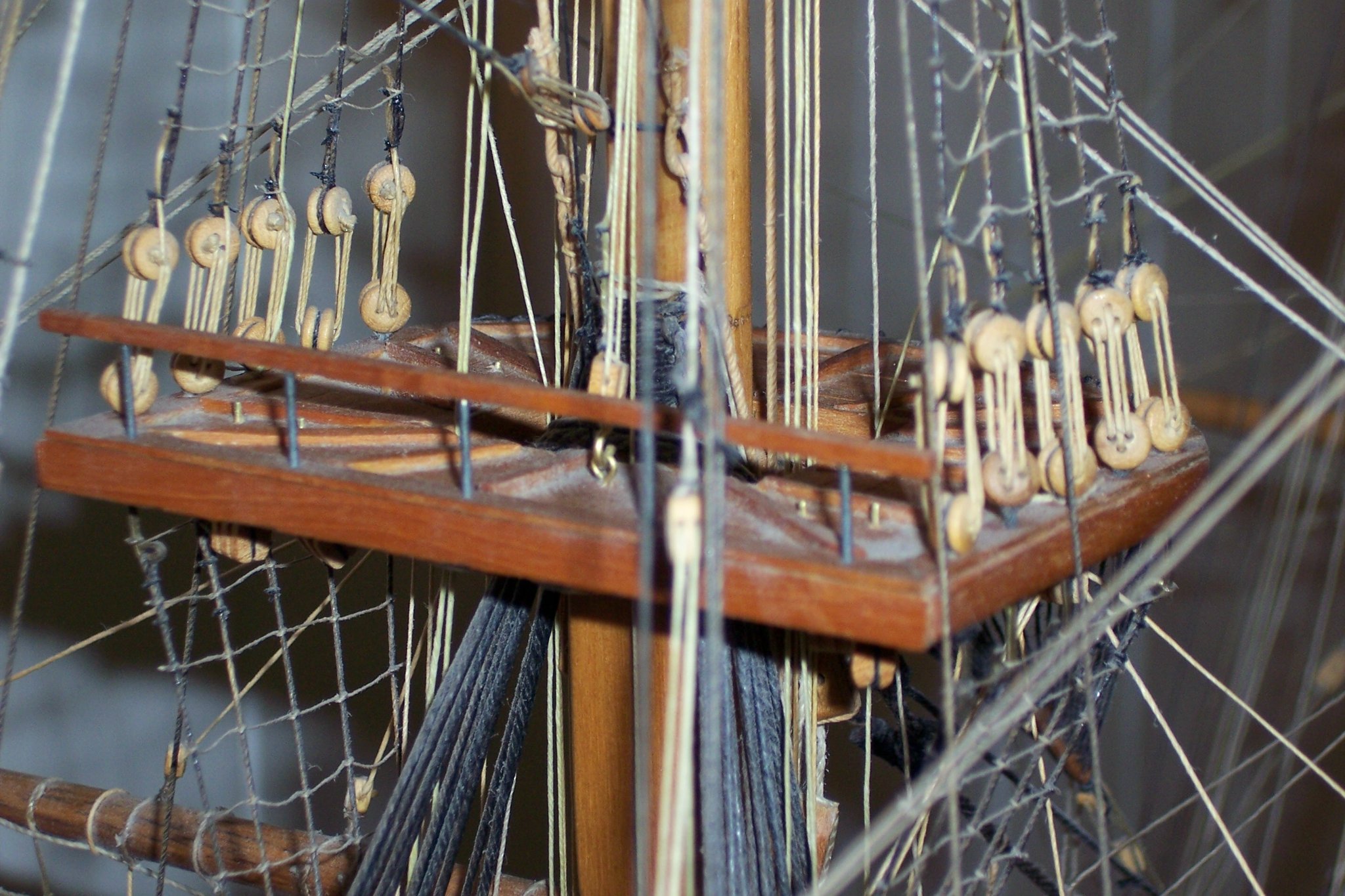
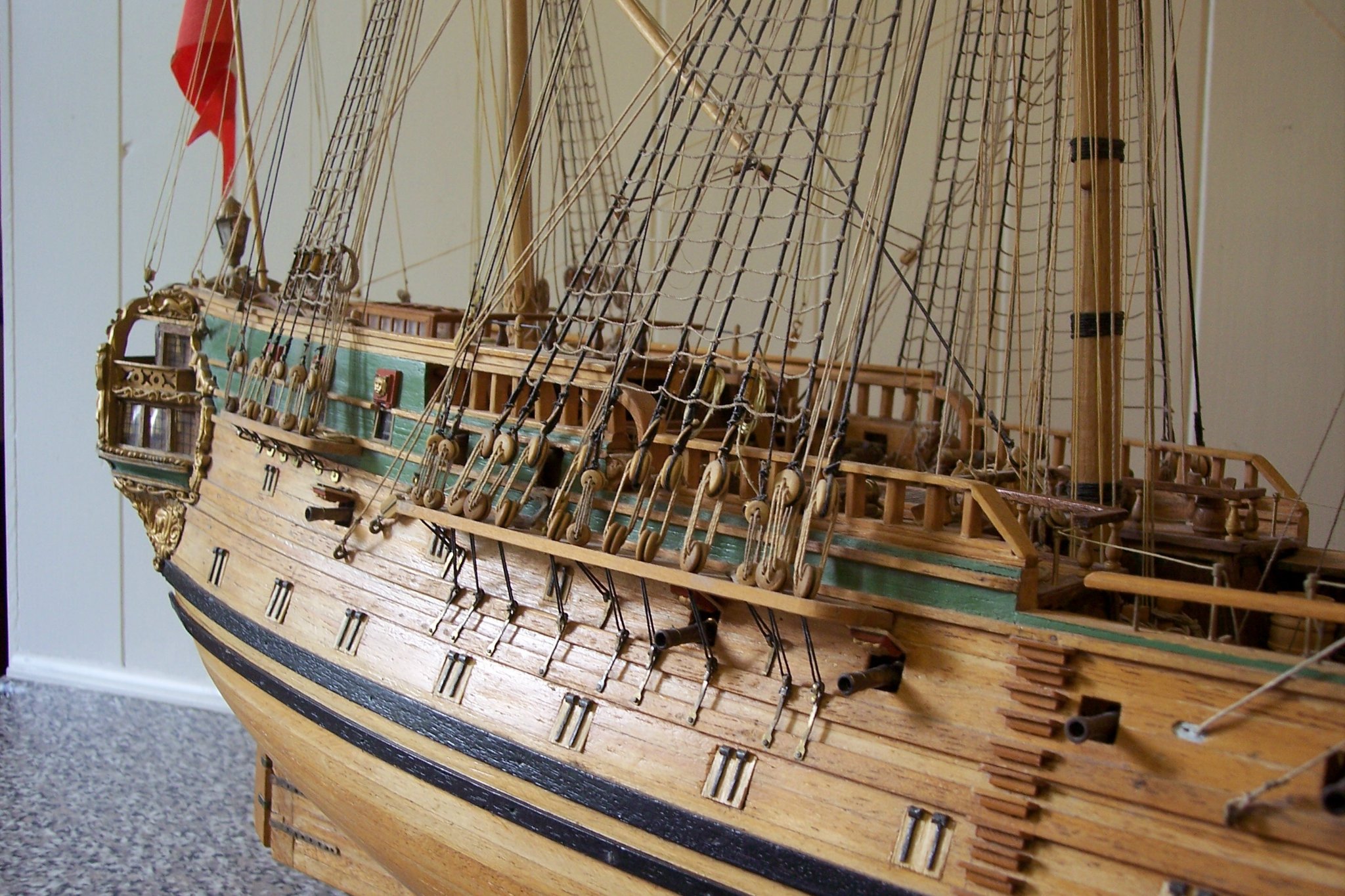
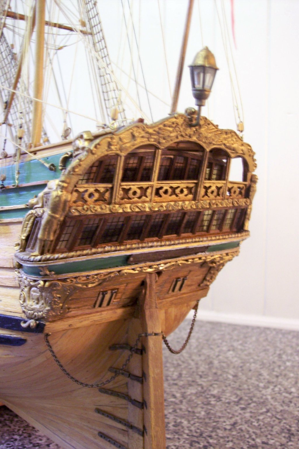
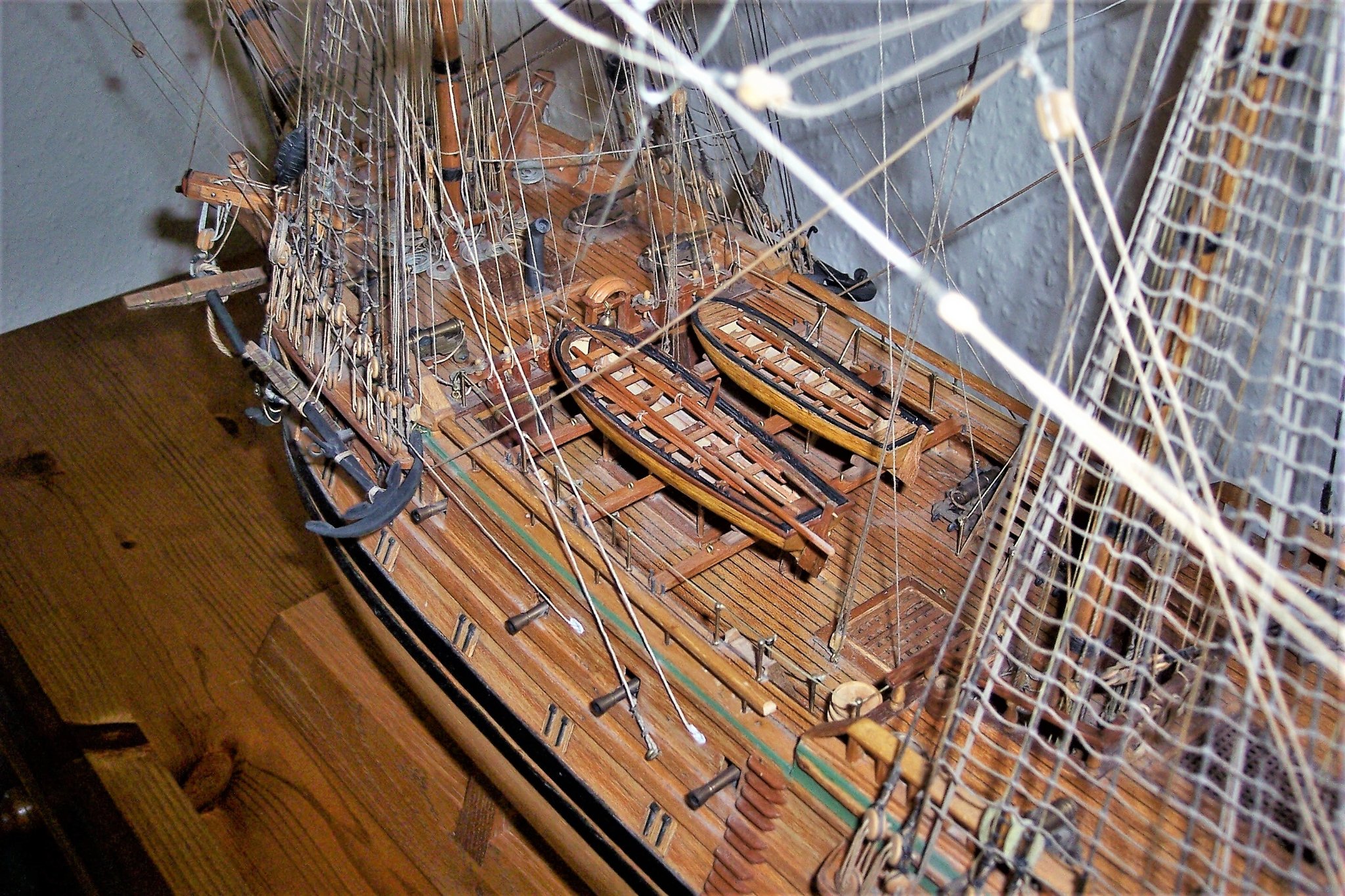
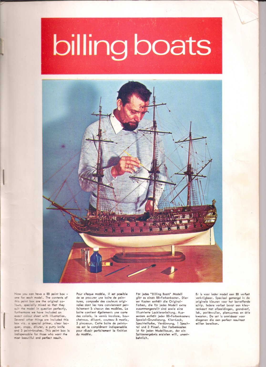
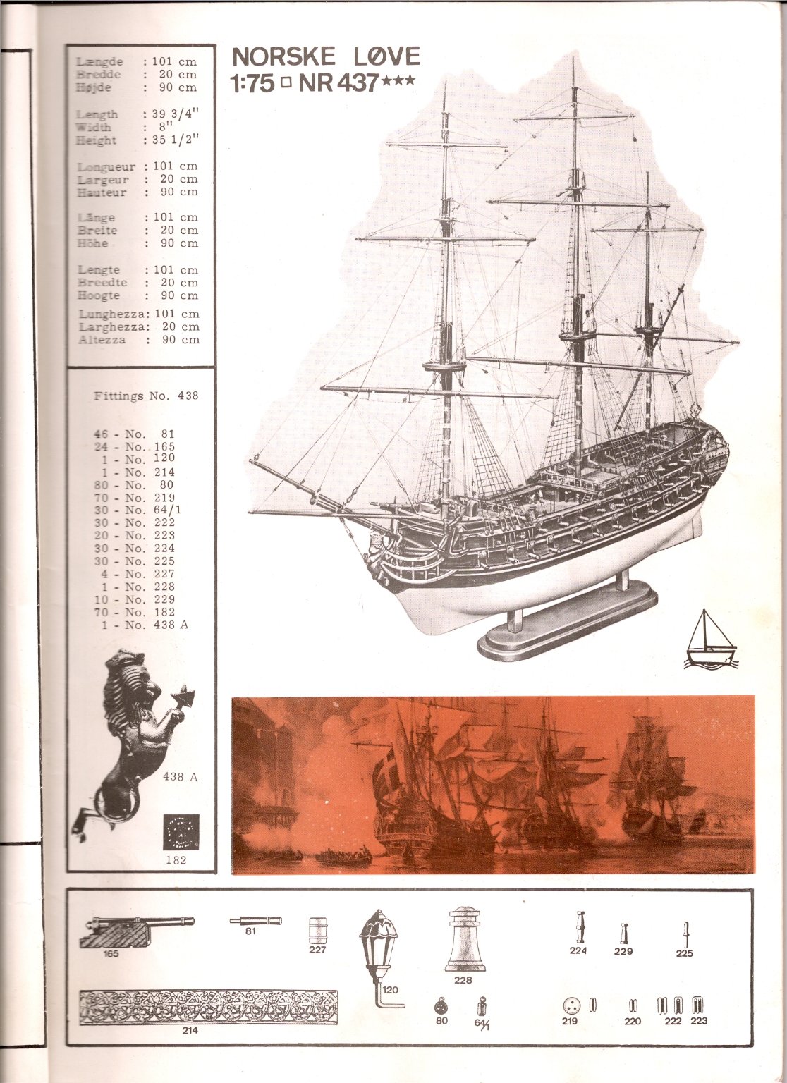
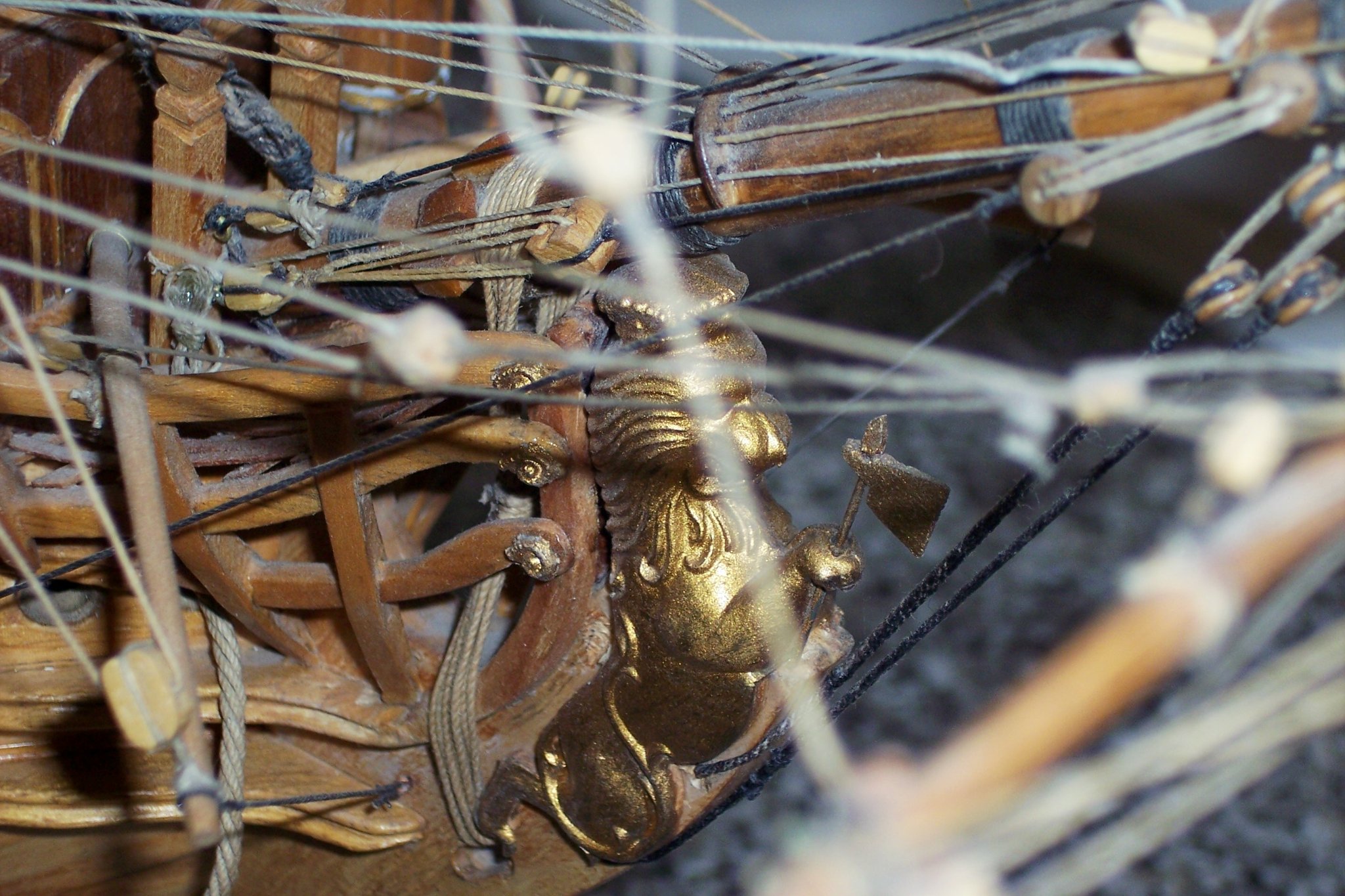
There are scant details on MSW of builds of this iconic Billing Boat kit, and periodically questions arise, often concerning inherited or partially built models requiring completion or restoration in the absence of plans or instructions, which in the case of Billing Boats were somewhat thin. So, in the spirit of giving some images that may help, I post here my Norske Løve story. I must have posted it somewhere before but can’t for the life of me remember where or when, but I do have my original log and photos. A cautionary note, this is a model I made over forty years ago, so the standard of fittings, and the ravages of dust have taken its toll on the condition. If I knew then what I know now I could certainly have made a better job of her but she remains a model for which I still have great affection, and I have resisted the temptation to upgrade her. Those not familiar with the finer points of our art tend to be seriously impressed by the sight of her. ( Norske) Løve Story More years ago, than I care to remember, before my office was a den of computer stuff, and before the digital age, I had a yen to build a large scale wooden 18th century warship. In those days it was either Billing Boats or Billing Boats, and as I browsed through their catalogue my eyes alighted on Norske Løve. It was the image of the modeller putting the final touches to the model that grabbed my attention, I wanted to be that guy. BB Cat cover Yes, I still have that original catalogue, in those days I actually went to a model shop, can you believe it! Pity I didn’t have the internet resource back then, but I did have the Longridge book and perhaps more importantly the Masting and rigging book by James Lees. Given that the Norske Løve was launched in 1765 it immediately struck me that the round tops provided in the kit, were oddly out of period, more 17th century than 18th The masts and tops were therefore scratch built to proportions given in the Lees book for ships of the correct period. The other main area that gave me concern was the head. In common with many wooden kit models this is a weak area with a less than realistic rails set up. Catalogue shot of the bows These were therefore also scratch built. I made other ‘modifications’ not necessarily in accordance with the plans, such as a skylight on the Poop and removeable skids to house boats which were not provided with the kit. Billing at the time (and probably still are) were in the habit of providing some plastic fittings for their kits such as blocks and Deadeyes, decorations etc. I seem to recall that the fittings kit was a separate purchase to the main build kit. This is Billings catalogue shot of the completed model. The build took me a couple of years, and my office resembled more of a joiners shop than an office. Drill stand and vice screwed to the desk top, wood turning model lathe and dremel permanently plugged in where now the printer and computer stuff reside. Everything was covered in a fine film of dust, but boy how I enjoyed that build. When completed the model sat in a lighted cabinet that filled one wall of the office and that’s how it stayed for some years. With the arrival of computers and the need to use my office for its proper purpose, everything was changed. Away went the cabinet and all the modelling stuff. 1153 Norske Løve then proudly sat uncovered on a long chest of drawers, where it resides to this day. Strangely things have come full circle and in retirement my office once again resembles more of a workshop, but I don’t think the resident equipment would appreciate a return to the heavy sawdust days. So here is the photo collection of my interpretation of Norske Løve, 1120 1127 1134 1138 1139 The head rails were scratch built using yellow pine, but there were several breakages before I got a satisfactory set. The Lower and Middle rails are mortised thro’ the head timbers, and the Main rail rebated into the head timbers. 04 02 I recall the exercise being long, slow, and frustrating. 1151 I particularly like the stern and Quarter galleries with their glazed lights, one of my pet dislikes with wooden kits are false windows or even worse stuck on windows, such as with the Mantua Le Superbe that lies forlornly in the loft. This is one area where Billing have done a good job, there was very little tweaking to this area of the build. 1140 1170 The modified tops, scratch built to proportions given by James Lees. The plastic rigging blocks supplied by Billings were replaced by boxwood versions. 004(2) 1133 1152 The main difficulty with single planked hulls such as this is that there is little scope for cocking it up if you don’t want to hide it with paint. I also have an aversion to stub guns so the lower ports are closed. 008(2) 010 The Poop was modified by the addition of a skylight, and the Ensign hand painted on cotton. The simplicity of the Danish flag lends itself to this method. 007(2) I think the anchors were aftermarket purchases. The Boats 002 005 Boats were not supplied so I had to create my own. 1132 1173 The deck fittings are mostly removeable to assist cleaning which is evidently overdue when this photo was taken. 1145 Dust build up is clearly apparent here. 1135 I really prefer models out of cases, they have so much more impact, and 1:75 scale allows for reasonable cleaning access which in this case takes about three hours every few months or so. I hope those who cross paths with this kit get some benefit from this vintage build. Regards, B.E. 22/03/21
.thumb.JPG.f8e1732adc86e1bde4e0598f680586b8.JPG)
.thumb.JPG.1841b369bedcdb9d1bc75a104b2a51fc.JPG)
.thumb.JPG.a1416091cf0847741ebbbb387ba0e817.JPG)


.thumb.jpg.edb49381dc9ff7947b4d5de8eb8d7efa.jpg)

- 5 replies
-
- 14
-
-
- Norske Love
- Billing Boats
- (and 1 more)
-
Thank you Thunder and Mike. @ Mike, - rather than clutter your log with photos of my build, I will put a separate log on here for folks to use as they will. My build long pre-dated MSW but I do have a short log that I must have put on some other site, but where I simply can't remember. I hope you will find it of use. Regards, B.E.
-
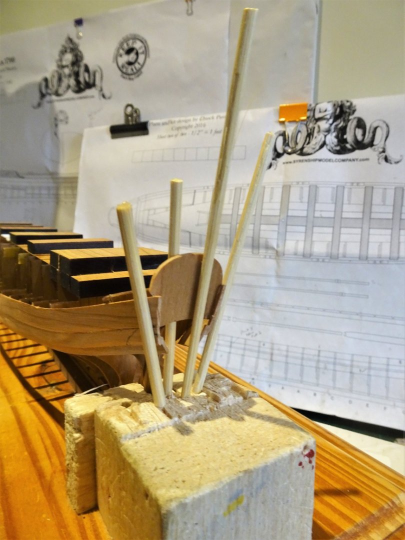
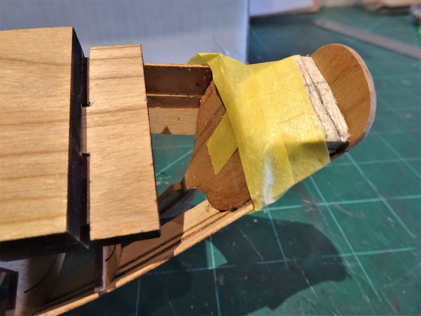
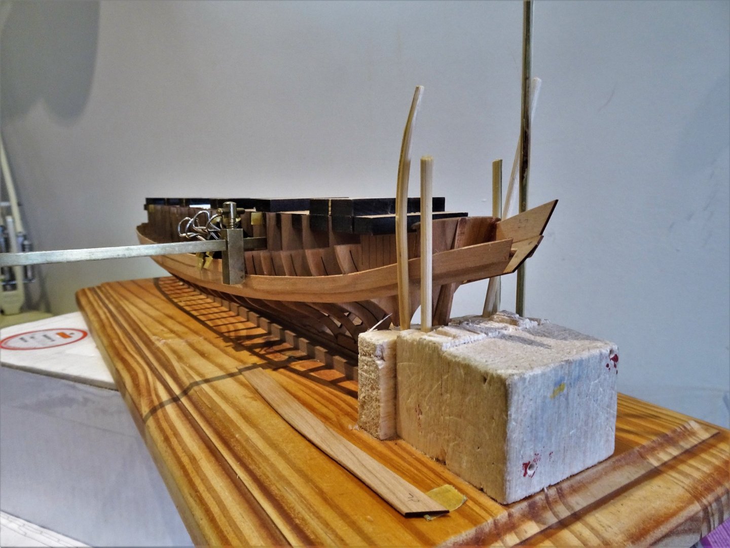
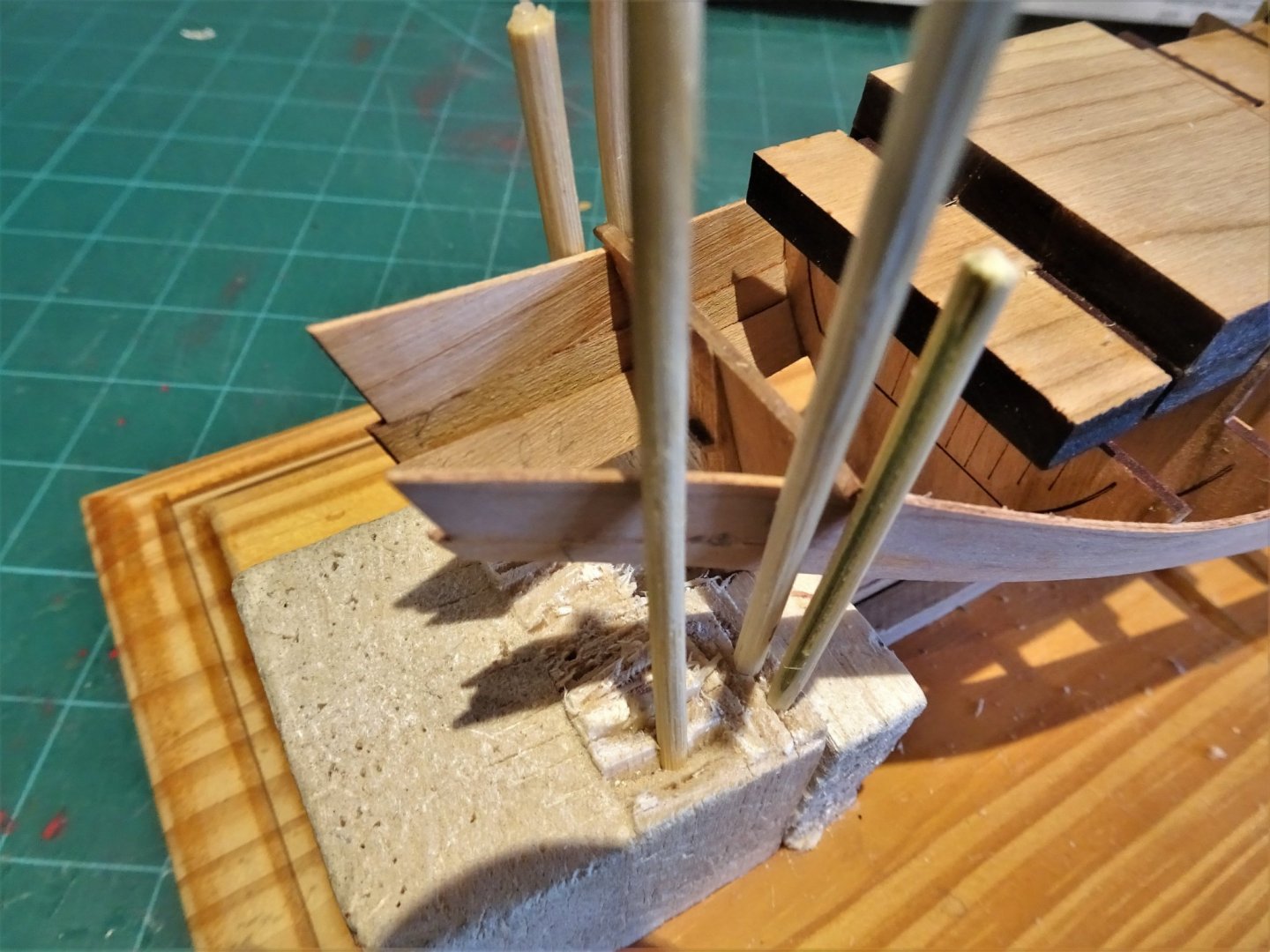
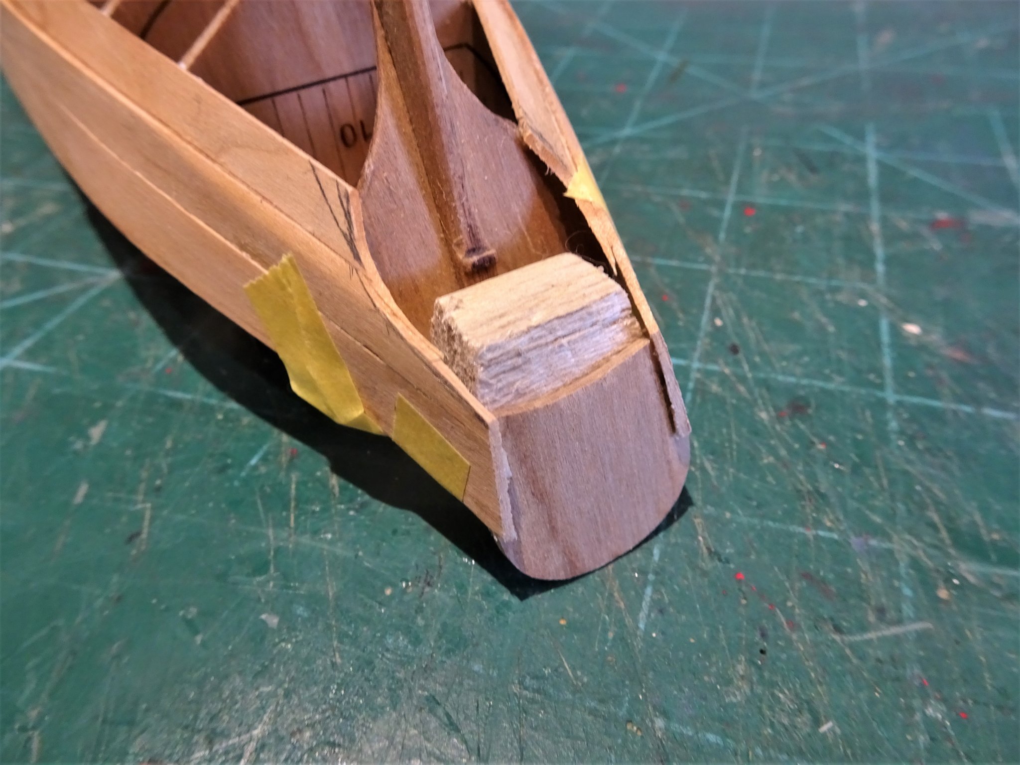
Post Eleven Flying Transom. This is another tricky piece to hold in the correct position whilst the glue bites. 1192 I used pva and bamboo poles to secure the angle and to support the Flying Transom whilst the glue bites. It allows me time to sight and check the Flying Transom set-up from various angles. 1201 1208(3) 1214 With the Flying transom in place I use a template taken from the plan to mark the curve down from the underside to the Transom base. 1224 The stern area is then taped up to provide stability for the next stage. 1226 I then carefully pare down to this line using a No 11 scalpel. 1228 The plank ends are then sanded back to the Transom face. 1234 1232 1231(2) The next stage sees her released from the base and the removal of the frame centres. B.E. 21/03/21

.thumb.JPG.9e768c714a5cffd20be113443f06bfd0.JPG)
.thumb.JPG.4a2ab13f9e0c870cc58770acb0e88a6d.JPG)

.thumb.JPG.d4aecb3ee27f30409eb892eb34c71ad0.JPG)
- 185 replies
-
- 18
-
-
- queen anne barge
- Syren Ship Model Company
- (and 1 more)
-
Hi Mike, I built Norske Love many years ago, and still have it on display, it is an impressive model, altho’ not up to modern standards in terms of fittings. I too found it odd that the tops are shown as round on a ship of 1765, (more appropriate to the 17th c) and I replaced mine with the more standard versions of the time. I also replaced all the deadeyes and rigging blocks with Boxwood versions. These photo’s that I put up in answer to a question somewhere long ago give you an idea of the use of proper deadeyes and blocks and the modified Tops. Regards, B.E.


-
Thank you Michael and Kirill. Post Ten Completing the planking. Three planks per side to complete what is the Sheer strake. For this work I have the hull the right way up as I find it easier to see and check the fit. 1126 I work with the model atop of the kit box which gives me a comfortable working position. 1128 The first bow plank (5) requires a bend to follow the bow curve into the rabbet and also a little twist so it lays square to the rabbet. A little tricky this one, on my build anyway; getting the plank to sit tight down on lower plank between the first Futtock and the rabbet was the main concern but a hairline gap should be covered by a moulding. The middle section (6) simply requires cutting to length and ensuring a close butt joint to the previous plank. The aft section (7) required a little shallow bending to round Futtocks 9 and 10 without tension, but I found it the most tricky to attach to the Transom and the extended plank run. 1135 I devised a bamboo pole support system to hold the plank tight against the Transom. Balsa wood support blocks prove useful in this situation. 1138 The final plank is put into place. It may all look a bit dramatic but the pressures are light and hopefully sufficient to produce a good bond. 1142 I left the hull to cure overnight. 1148 I have started to feather the clinker towards the stern, more to do but I think I will wait until I have fitted the Flying Transom which will stop any flex in the planking. 1145(2) 1146(2) 1155 The next stage is to fit the Flying Transom. B.E. 20/03/21

.thumb.JPG.e03572f489d6c665799c7329bf690fe2.JPG)
.thumb.JPG.ce93aa81210d093520eacd6a9bfe7b6f.JPG)
- 185 replies
-
- 10
-
-
- queen anne barge
- Syren Ship Model Company
- (and 1 more)
-
Excellent work on the masthead ropework Michael, it looks splendid. You should take up Macramé 🙂 B.E.
- 222 replies
-
- 2
-
-
- reale de france
- heller
- (and 1 more)
-
Hi Michael, I hadn’t realised that you are safemaster until Hubac made a link reference to my Le Praetorian build. Your work on these Heller kits is second to none, and your current project is no exception. I still fondly remember your 1765 Victory build, and the Figurehead, a magnificent bash if ever there was one. Glad to see you are still creating your wonderful models. B.E. (Maurice)
- 222 replies
-
- 1
-
-
- reale de france
- heller
- (and 1 more)
-
Post Nine Fitting planks 3 and 4 This is where the clinker comes into play. Port and Starboard can get a little confusing when it comes to these pre spiled planks. What initially looks like the outboard face of Plank 3 on the fret is in fact the inboard face. When working with the hull inverted I have to remind my addled old brain that Port is on the right and Starboard on the left. Having bevelled the inward face of plank 3, the corresponding bevel of plank 1 is carefully pared down at the bow to allow plank 3 to fit into the stem rabbet with a feather edge. I find the 2mm Swann-Morton chisel blade perfect for this. 1071 The plank is water/heat treated to form the bend around the bow, and a small amount of lateral twist is imparted to the end of the plank to allow it to sit flush against the stem rabbet. 1069 With the plank temporarily in place the aft end can be marked for trimming on Futtock 2. As with the first planks I prepare both sides before any glue is applied. The Portside plank went on without trouble using ca, but I keep a small pot of acetone at hand to clean off any overspill on the face of the plank. The main concern now is to ensure that the opposite side plank has a uniform meet at the bow rabbet. 1073 For this reason and to give me a little tweak time I used pva for the rabbet join and the first two Futtocks. This allowed me to sight along the bow and make any minor adjustment before clamping in position. Use of ca would have precluded this. 1078(2) Light pressure is used and the model is set aside for the pva to cure. 1083 Plank three successfully (I hope) attached. I continued to use pva which worked out ok. 1084(2) It will stand a little more feathering into the bow but that can wait awhile. Onto Plank 4 Very little fiddling needs to be done, I did impart a little twist towards the end to allow the plank to lie flat without tension across Futtocks 9 and 10 and the Transom. 1100 At the sternpost I added a balsa support piece to brace the planking for gluing the extensions beyond the transom. 1106 The final plank 4 goes on without incident. 1113 1108 1111 At this point the clinker has yet to be feathered out at the stern. Onward and upwards to the sheer strake. B.E. 17/03/21

.thumb.JPG.184239cff6faac73f91d30e855bc5b51.JPG)
.thumb.JPG.ae40b33ceb38faea1d76546101052c8b.JPG)
- 185 replies
-
- 15
-
-
- queen anne barge
- Syren Ship Model Company
- (and 1 more)
-
Great artistry and innovation to produce this wonderful model Kirill, many congratulations on a project well done. Regards, B.E.
- 228 replies
-
- 5
-
-
- spanish galleon
- lee
- (and 1 more)
-
Hi Wood gnome, thanks for looking in. Yes, once the false deck was installed, which was cut around the bulkhead tops, the tops were cut down and covered by the the Margin Plank. The bulkheads do not correspond with 'frames' which on the kit are represented by the timberheads added later. The inside of the bulwarks were then lined. Hope you enjoy your Fly build. B.E.
-
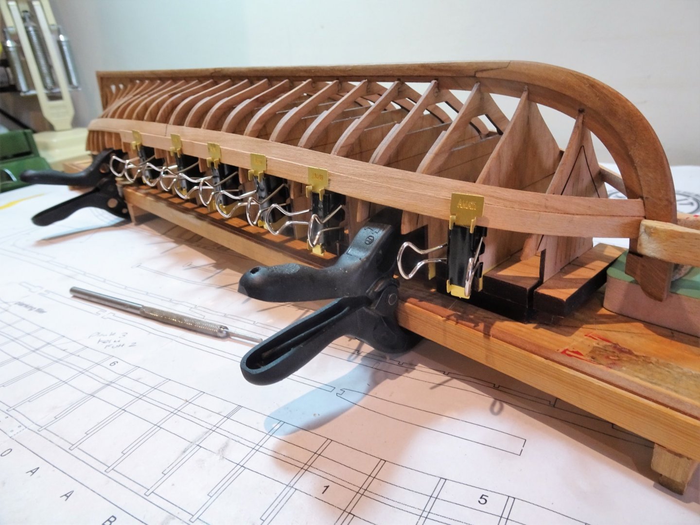
Hi Derek, I too have made my own like yours, but Amati have brought out this more formal set using a brass plate. I first saw them on one of James Hatch’s logs, they are called a clamp set (Item 7377) and contain 12 clamps. I still use my home made ones as well, but these are a useful addition to the clamping arsenal, and they don’t exert too much pressure, which is good when working on more delicate framing. If I want to exert slightly more pressure I bend the handle on the homemade version slightly inwards. Cheers, B.E.
- 185 replies
-
- 4
-
-
-
- queen anne barge
- Syren Ship Model Company
- (and 1 more)
-
As a picture Chuck, and all down to your great design features, and guidance. I'm feeling a little more relaxed now that the frames are secured by the planking. 👍 B.E.
- 185 replies
-
- 2
-
-
- queen anne barge
- Syren Ship Model Company
- (and 1 more)
-
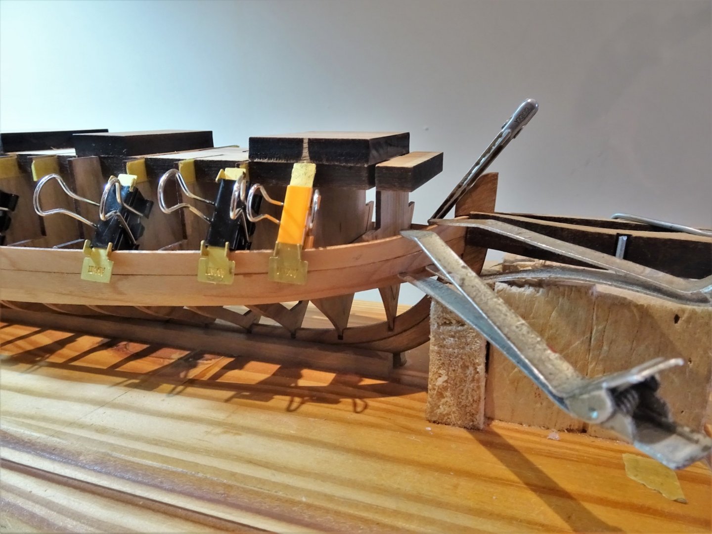
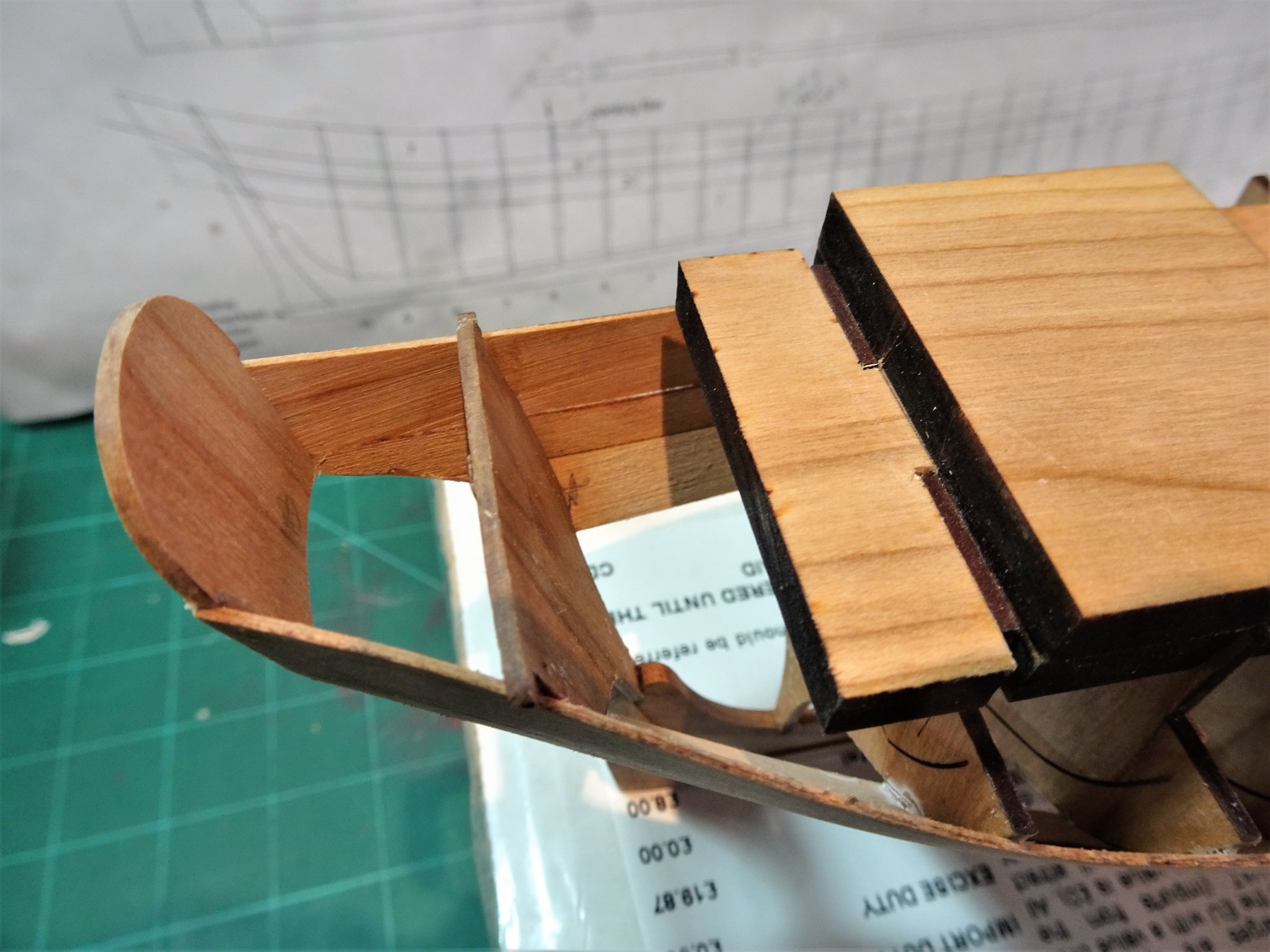
Post Eight Progressing the planking strakes. I begin with the Starboard aft first strake which is a simpler arrangement than the bow section. 1024(2) Dry fitting the aft plank. I imparted a shallow bend to assist the plank to lie flat across Futtocks 8 and 9, followed by a shallow outward bend between Futtocks 10 and the transom. This is to create a concave sweep running into the Flying Transom. 1025 This photo shows the concave curve that will run to connect with the Flying Transom. 1027 As with the stem, a support block is temporarily fixed to the board to support the Transom and counter any lateral pressure when gluing. At this point I haven’t glued the aft plank to the transom, I will do that once the second (Portside) plank is fixed, and I can tweak the set up with both in place. 1030 Aft piece shape. 1051 The Transom is held steady for the gluing. 1050(2) 1036 1048(2) 1063(2) A small block of balsa is used to support and protect the transom. B.E. 13/03/21
.thumb.JPG.247632b19b7d8f6cb1abd3d370e41662.JPG)

.thumb.JPG.30ed9cbb5cac1c46846c74c74c6538b4.JPG)
.thumb.JPG.bdea1976ee77066eb5dd29c5ed577168.JPG)

.thumb.JPG.386e2c89e471f41b524a5f74a5372b19.JPG)
- 185 replies
-
- 20
-
-
- queen anne barge
- Syren Ship Model Company
- (and 1 more)
-
Thanks Rusty, sometimes that ‘handle’ feels a little fragile, this is a build that surely concentrates the mind, but enjoyable all the same. Post Seven First fixings I have spent most of yesterday faffing around with the first planks. The final tasks before gluing is to bevel the plank for the bow /rabbet fit and trim the plank to terminate at the forward Futtock ‘O’. The Portside plank went on fairly easily, but the Starboard version not so. To my increasing frustration the ca initially refused to grab on several of the Futtocks. The bow strake/rabbet connection was particularly stubborn and in the end I left it until last and used pva which allowed me to tweak the level to match the Portside. 0991 There is an element of flexibility in the as yet unsupported stem, and it really needs holding in the vertical line whilst the first plank is applied. 1013 1012(2) 1007 1001(2) 0993 0996 1018(2) 1009(2) I am satisfied with the outcome, and not a little relieved that this first critical task is completed. B.E. 12/03/21

.thumb.JPG.d254b03503115cc3e0be42e4431a6c0d.JPG)

.thumb.JPG.592d84e75d70298b0dde6ee98d7cd8c2.JPG)
.thumb.JPG.f7adbf6474856d3a069649b45fc89bfc.JPG)
.thumb.JPG.f52b2b6c255cc72254c86778d4624267.JPG)
- 185 replies
-
- 14
-
-
- queen anne barge
- Syren Ship Model Company
- (and 1 more)

.JPG.9f355d8bee589809a03f008baf58038e.JPG)
.JPG.f8a0f7ea1df4fbb8df8478c126a93068.JPG)

.JPG.bba52d0595d83690fb6dc592b592f0c6.JPG)
.JPG.47fb776ed65cc4d619d394faab24781b.JPG)

.JPG.9b9029a58c2840559d7e3c9edb6b11ac.JPG)
.JPG.0e9760955e9c495e3411585aba0e0bac.JPG)
.JPG.3eef534e3898eb0c533260241bb12a3d.JPG)
.JPG.f1c9983cdbf98f59077b7a7c4295eeaa.JPG)
.JPG.ab16336fcd354d22302288b0d69e9248.JPG)
.JPG.6c02f86784550ca5a03210e34ae5b9c8.JPG)
.JPG.52891b9a34786e33d50cf943af958937.JPG)
.JPG.731f0a8d7f03047dd54968a3e69c2e62.JPG)
.JPG.1d856f4fcec9f1d41b8a91bc6bf84b47.JPG)

.JPG.2b3c5154c0420d4fdd21a308154254c0.JPG)

.JPG.8486c549d8427e7e2168d80fb3f30d41.JPG)


.JPG.d65cfc368953a0dbad409241a5bd23b6.JPG)
.JPG.d849677b79f6a6d778a89d99b80f70ee.JPG)


.jpg.c0fb7e20c537c934c98a32b42b2338e0.jpg)


.JPG.30337c4e8fb728df6f6b420609e477b6.JPG)
.JPG.faa06b19b876dca1a2f584c4be59a5ec.JPG)


.JPG.cb7f557fa92353a214ca3ec7a3f9bc96.JPG)


.JPG.7463f1912814f96609bd3691c17b51b3.JPG)
.JPG.e3529a1b25b8e45d20e34b9b2574723a.JPG)


.JPG.09c09369cf18fb3bc2a386785f543b8d.JPG)

.JPG.293d3ac6ead2efc699f7366c173c13a6.JPG)


.JPG.7d64bab75d4676d98b8ddc84e9f2f00e.JPG)


.JPG.a4c4d5b0fab7d4cfb14e97688c166bf6.JPG)
.JPG.53afbd4c851788f44ca0d267926d2f96.JPG)
.JPG.6a8ee8a9f773485b12965ade670f8253.JPG)

.JPG.e9020923397edce4ec3cf4d4273a2afe.JPG)


.JPG.f245b62a91756c3c0586949c9cbc388a.JPG)
.JPG.e31775774bb7c28474efd1740ff45c33.JPG)
.JPG.b0edab72ad3a4628fb3bf675d9cc3667.JPG)