Landlubber Mike
-
Posts
4,544 -
Joined
-
Last visited
Content Type
Profiles
Forums
Gallery
Events
Everything posted by Landlubber Mike
-
 That's quite a bit of a warp Jason. Given that it's just at the end, I wonder how successful it will be to soak and flatten - and even then, is it worth the possible future bother and frustration? If you have a scroll saw, I would recommend cutting out a new piece for yourself (or you can cut it out by hand). My Unicorn keel had a warp like that, so I just cut out a new one which wasn't all that difficult to do. The problem will be finding a supply of larger sheets of plywood that aren't warped - I bought some from Micromark, which were all warped (to their credit, they refunded me the purchase price). I then bought a stack of 6 sheets of plywood from Hobbylinc, and I was able to find one from the batch that worked. If possible, I wonder if you can find thin sheets of MDF instead, which is probably much less prone to warping. The Pegasus kit comes with very good quality MDF (no warps, very sturdy and heavy duty), which makes me wonder why other kit manufacturers don't take that approach. Just out of curiosity, what is the Jason's figurehead? I'm thinking about carving my Unicorn's figurehead, so I've been doing a little research on figureheads and carving in general.
 -
Wow, that's really nice of Occre. Thanks for reposting your build log. I had no idea that this model was so big - should be a lot of fun
-
Where to find 28 gauge black wire?
Landlubber Mike replied to David Spindle's topic in Masting, rigging and sails
I bought beading wire in various gauges from Michaels that came in black. The black coloring did have a tendency to scratch off but it was easy to touch up with a little black paint. -
Keith, I'm very excited to follow this build. I have the Friedrich Wilhelm which is a very nice kit, but the Royal William seems to be the pinnacle of all kits. Looking forward to following your journey.
-
Consider yourself fortunate as my 15-month old twins have been sick and, err, somewhat on the cranky side You'll have to let me know if you're down here in the future.
- 800 replies
-
- 1
-

-
- snake
- caldercraft
- (and 1 more)
-
Jason, your Snake looks great and I'm excited to follow your Jason build. Very cool to build a ship with your namesake, and especially one that is gorgeous like that one (I really love the look of the Artois class)
- 800 replies
-
- 1
-
-
- snake
- caldercraft
- (and 1 more)
-
Tim, I'm in the DC area but am supposed to go to a wedding up in CT in the fall. If my family will let me squeeze it in, I'm hoping to make a trip to visit the Morgan, as I have the kit on my shelf. If I can make it, I plan on taking plenty of pictures that I can share with you and others on here that might be interested. Sorry to interrupt your log Gerald. Love your work - your Morgan is setting a very high standard for my future build
-
Harbor Freight Workbench
Landlubber Mike replied to Landlubber Mike's topic in Modeling tools and Workshop Equipment
I see a lot of people have these benches against the wall with power tools on them, but I found that I needed more depth than what these benches give (I think it's 20") to safely use my Byrnes table saw and thickness sander (depth is ok for things like the disc sander, mill and lathe). What I ended up doing was putting two of these benches back to back, with one side against the wall - essentially, building out a workspace island where I could access the drawers on both tables, and access the machines on each of the tables. On the side against the wall, I attached a power strip to one of the benches, as well as a couple of swing arm lamps. That gave me more useable space than putting the two tables alongside one wall, or building an "L" configuration with the two benches in a corner. -
Harbor Freight Workbench
Landlubber Mike replied to Landlubber Mike's topic in Modeling tools and Workshop Equipment
Wow, very nice set up you have there! -
Thanks Spyglass. For my Badger, I set up my pedestals very similarly. I think I centered the hull on the baseboard (not including the bowsprit, driver/boom and maybe not the stem too, I forget), and then positioned the pedestals 25-30% from the ends. I agree that you don't want them too far apart or too close together.
-
Thanks very much Spyglass, this is very helpful. I read through your Pegasus log the other day, which reminded me that I needed to start thinking about the mounting set up. For my Badger, I used the Model Expo brass pedestals. I forget exactly which I bought, but I think it was the 1.25" and 1.75", and then used grinding bits and a cut-off wheel to shape the cut out slot so that the model would sit with the waterline parallel to the building board. If I remember correctly, I cut down the tops of the slots a bit, and shaped out a sloped groove to accommodate the fact that the bottom of the keel was not parallel to the waterline. I'll have to try your felt approach for fine adjustments, that sounds like it would work perfectly. Taking another look at your log and Dan Vadas' logs, it looks like I can just drill the hole, rather than milling out a full slot. I'll have to think about this a little more - though, maybe I'm just over thinking things
-
Very nice brick platform! It came out fantastic. In the model railroading space, you can buy printed paper that simulates bricks, and they even have styrene brick patterns that you need to paint. Your approach looks much nicer in my opinion.
- 2,191 replies
-
- 1
-
-
- confederacy
- Model Shipways
- (and 1 more)
-
Really nice work Ben. I have the TFFM series, and while I don't plan on scratching a Swan class in the near future as I have the Pegasus kit, it's a real treat watching you execute the scratch build.
-
Frank, I was going to say that with the nice results you're getting now, you probably only need to single plank it. Maybe I should try it to save on buying tubs of filler like Augie
-
Thanks very much guys, I really appreciate it. I need to touch up the joints a bit, but overall, I'm very happy with how the stem came out (better than I expected). Another approach would have been to cut out the stem as one piece, and scribe lines into it to simulate the various components. That probably would have been a lot faster, but you probably have to make sure that your lines are very clean for it to look good. Another thing I need to do in the very near future is to install the pedestal mounting components to the keel. This build I'm going to epoxy nuts inside the keel and run stainless steel bolts through the pedestals and into the nuts like many others on here have done. I had made the mistake with my Badger of waiting until after the ship was double-planked to drill the pilot holes for the wood screws that came with the two pedestals. I forget if I drilled them by hand or not, but the holes must have not been perfectly perpendicular to the keel (or I screwed the screws in at a slight angle) as there is an ever so slight lean to the ship when on the pedestals that I could never fix. By pre-drilling holes now at this stage just working with the keel, and using nuts and bolts rather than wood screws, I should be able to get things much more square. What I'm still working out is whether I should use my mill to drill a hole for the bolts, or instead, to use my mill to mill out a narrow slot in the keel. I'm thinking the latter approach would give me more control and allow me to follow the line of the bolt's path, but I would welcome any thoughts on the best approach.
-
Looking great Frank. Very tight and neat planking! Is this a single-planked hull or double?
-
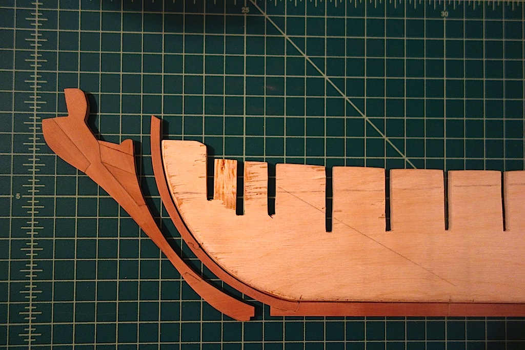
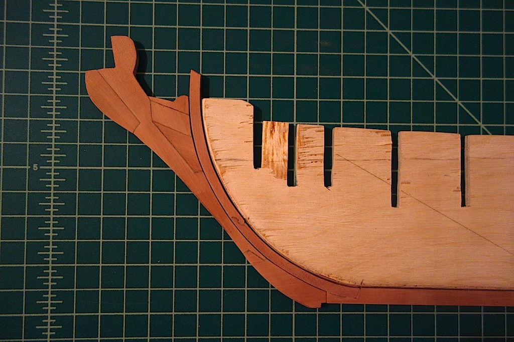
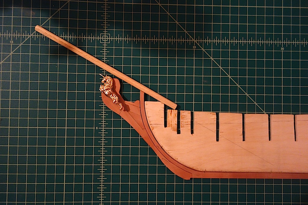
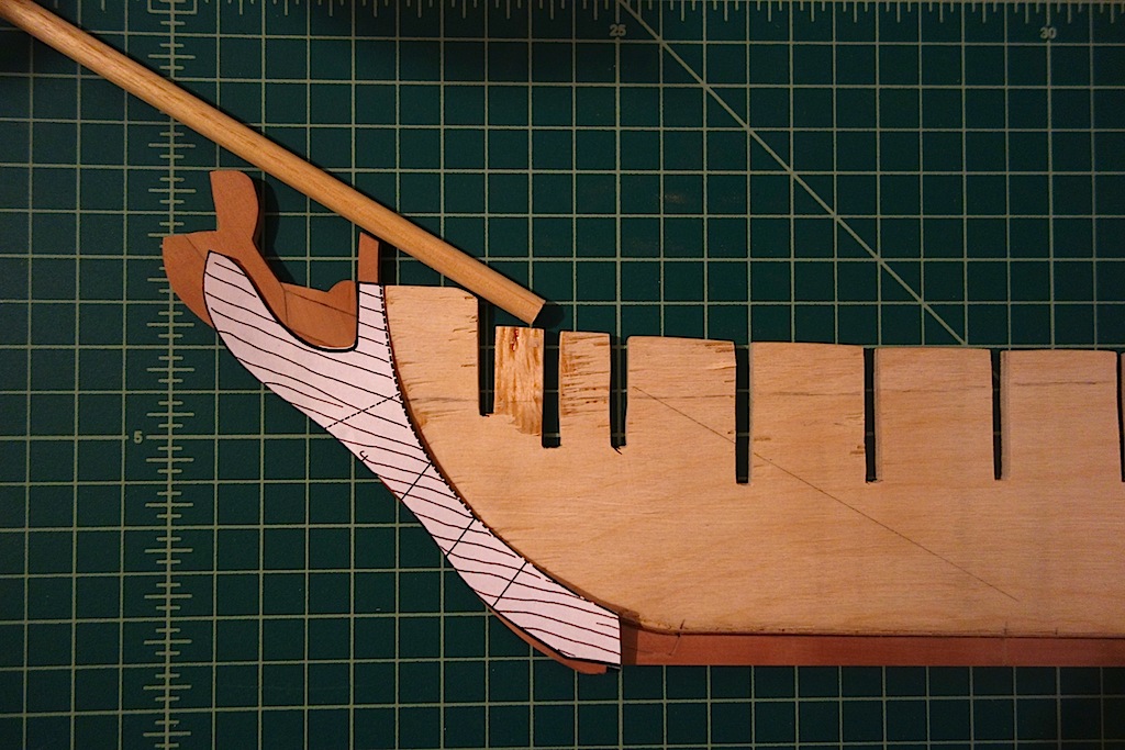
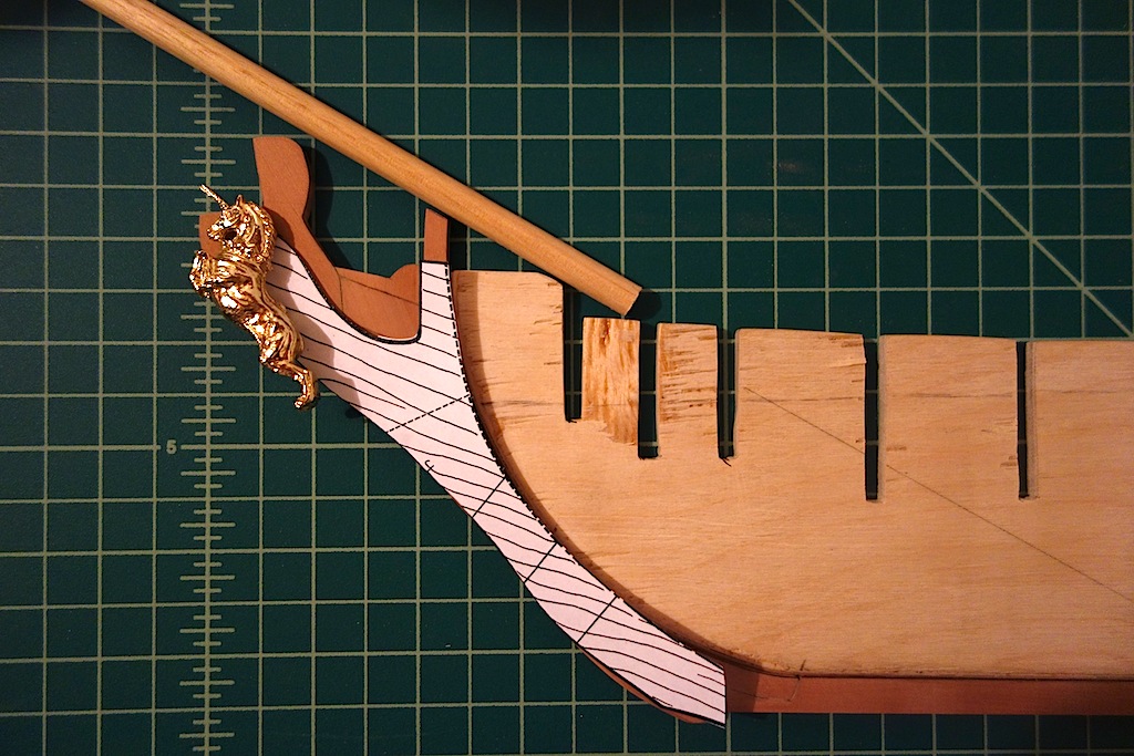
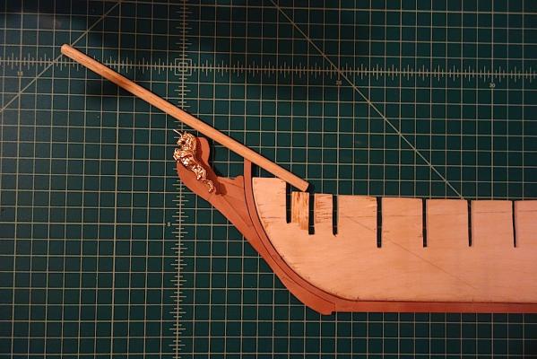
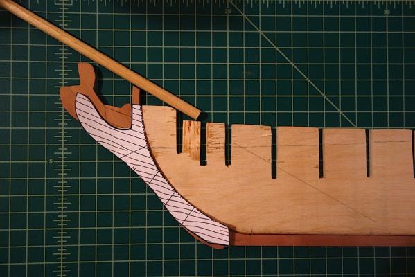
I made some more progress on the stem, building the five remaining pieces (main piece, bobstay piece, chocks, lacing, and the piece holding the main stay collar). I ended up following the general pattern/shape of pieces from one of the stem diagrams in the AOTS Blandford book, with a slight modification to not include a fore foot as part of the gripe. It seems like stems were constructed in all different ways, so I picked an example that seemed a little easier for me to execute given that I'm very new to the power tools I'm using. A few of these took multiple attempts on the scroll saw to get right. Thankfully I got the main piece on the second try as it is pretty complicated. I still have to add the holes for the bobstays and the main stay collar, as well as shape the top of the main piece to conform to the eventual head rails - I figured I would leave a little extra to work with as I finalize what the head rail configuration would look like. I also need to thin down the stem a bit where the figurehead will sit, as well as cut a slot into the figurehead so that it can sit on the stem. Either that, or I need to carve a new figurehead which I'm tempted to at least try You can see that I also decided to glue all the pieces together, but not to the stem/keel at this time as it will be a lot easier for me to shape the stem off the model, and probably to plank it as well. I ended up penciling in one edge of the joints to help better define the joint. In some areas, the joint was probably a bit wider than I would have liked. The trickiest is cutting scarpf joints against curved pieces - not fun! So, I put very diluted PVA into the joint and sanded the stem over the joint so that the sawdust helped fill it. I still need to make a few touch ups, but I'm actually quite pleased with how that all worked, especially as it toned down a bit of the pencil to make for more muted joint lines. So, adding the bowsprit and figurehead, the stem area should look like this: I think this is fairly close to Chapman's plans and other similar vessels, where the figurehead sits up higher and closer to the bowsprit, and sits on and within the stem as opposed to attached to the end of the stem as in the kit instructions. In the pictures below, you can see how the stem on my build differs from the kit stem. Next up is to start working on the bulkheads, and to modify the keel for the new angles to the decks and the scratched stern. Thanks for reading!


-
Hi Colin, beautiful work. I'm using the McKay AOTS book as a guide for my Unicorn build, and find it incredibly detailed and helpful. I thought that this could be a gorgeous ship to scratch, and I got my confirmation in coming across your build log today
-
Very much looking forward to seeing what you can do with this kit Denis. Beautiful ship, great kit, and skilled modeler all make a wonderful combination for greatness. I'm subscribed
-
John and Ian B, very nice models and artwork. I don't think my wife is as understanding about the decor. She kept asking me where I would put my 26" Badger - wait until she finds out that my next models are close to 50% bigger
-
Ian, I'm glad your Unicorn survived the intergalactic wars, and with no battle scars Thanks very much for passing along this information. That Flynn thesis looks like it has a lot of very good information, I'll have to print it out and give it a read. It's nice that he included the Pandora, which is a 24-gun frigate descendant of the Unicorn. I think I'm going to go with the 4-strake wale - or at least, make the width of the wale on my build equal to four of the strakes on the model. By bumping the wale out in thickness by an extra strake above and below the wale on the plans, the wale really sets up nicely with Chapman, particularly with the location of the cheeks. I spent some more time last night sketching out the shape of the stem. I think I got it fairly close in the pictures above, but I am going to angle the figurehead a bit more and push it back a millimeter or two from the sketch from a couple of nights ago. I'm still contemplating how to construct the remaining 5-6 pieces of the stem - mostly, to give myself flexibility on whether I ultimately use the kit figurehead or try carving one of my own. What I'm thinking I might do at this stage is to glue on all remaining pieces aside from the one or two pieces on which the figurehead will sit, this way I can do fine tuning of the pieces off the model to accommodate the figurehead. The nice thing is that there does not seem to be any set standard on how to construct the stem, as from what I've seen looking at plans for the Pandora, Blandord and Diane (among others), they have have slightly different approaches.
-
Very nice work Ian. I almost wish that I could spend an afternoon with you to learn from you on how to do metalworking. You really are a pro, all the more impressive given the small scale of the work. Is the spectacle plate for the rudder chains? On my Badger, I took the easy way out by bending a piece of metal strip, drilling holes into the strip and rudder, and inserting a small eyebolt on each side. Yours looks much much better
-
Very nice work as always Augie. She's coming along very nicely!
- 2,191 replies
-
- 1
-
-
- confederacy
- Model Shipways
- (and 1 more)
-
Hi Joe, very nice work. Looks like the gunport patterns are in the right position and with the right curvature. I remember having a few choice words for the gunport patterns on my Badger I'll be following your decision on the drill and fill method for the treenails closely. I went with the bamboo skewers through the draw plate approach on my Badger, which probably takes much more time than the drill and fill method. The Byrnes draw plate worked very well, but I can't tell you how many times the skewer wood broke at or just before the final hole in the draw plate. Toothpicks probably would have been a step easier. For the drill and fill method, I worried that the paste would flow into the wood grain leading to streaks in the planks, but it seems like most people don't have that problem.
- 302 replies
-
- 1
-
-
- granado
- caldercraft
- (and 1 more)
-
Nice work Mundie. I also find it much easier to work in metric. Congrats also on your degree!