Louie da fly
-
Posts
7,990 -
Joined
-
Last visited
Content Type
Profiles
Forums
Gallery
Events
Everything posted by Louie da fly
-
 Having the large photo in your signature is a bit strange - I've come across it in putting up a link in a post, but I have a couple of links in my signature and they didn't do that. Steven
 -
Beautiful work, Chris. That shape is much rounder than I'd ever thought - very suitable for carrying cargo. Steven
- 179 replies
-
- 4
-

-
- shipyard
- wütender hund
- (and 1 more)
-
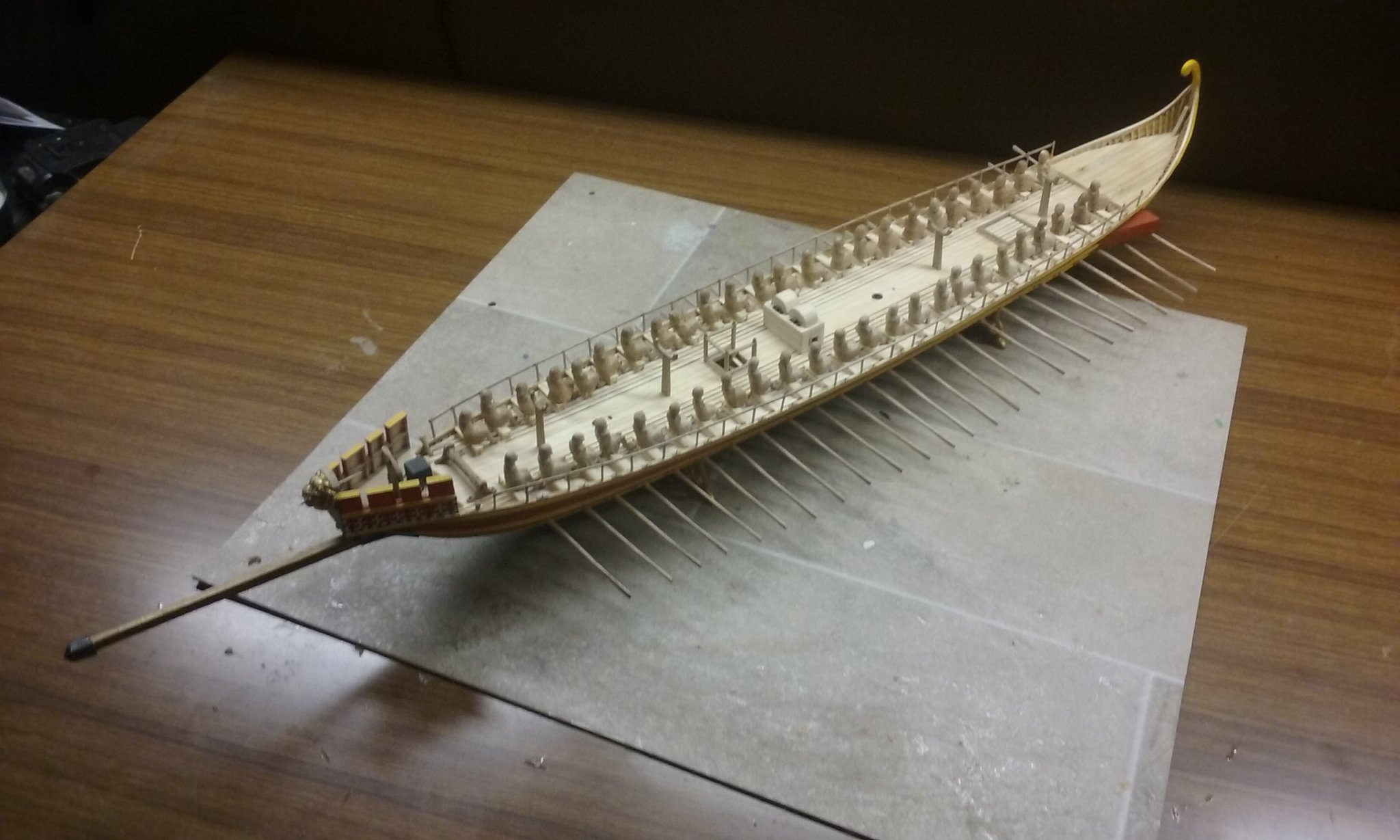
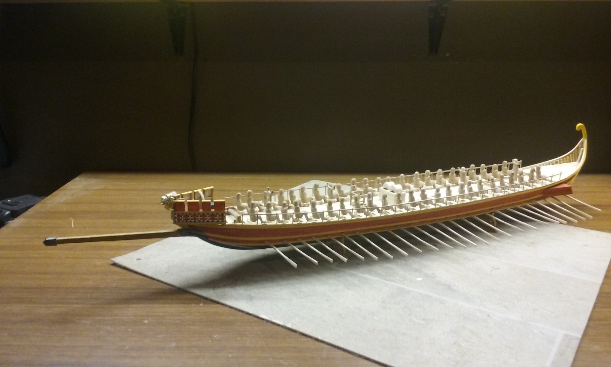
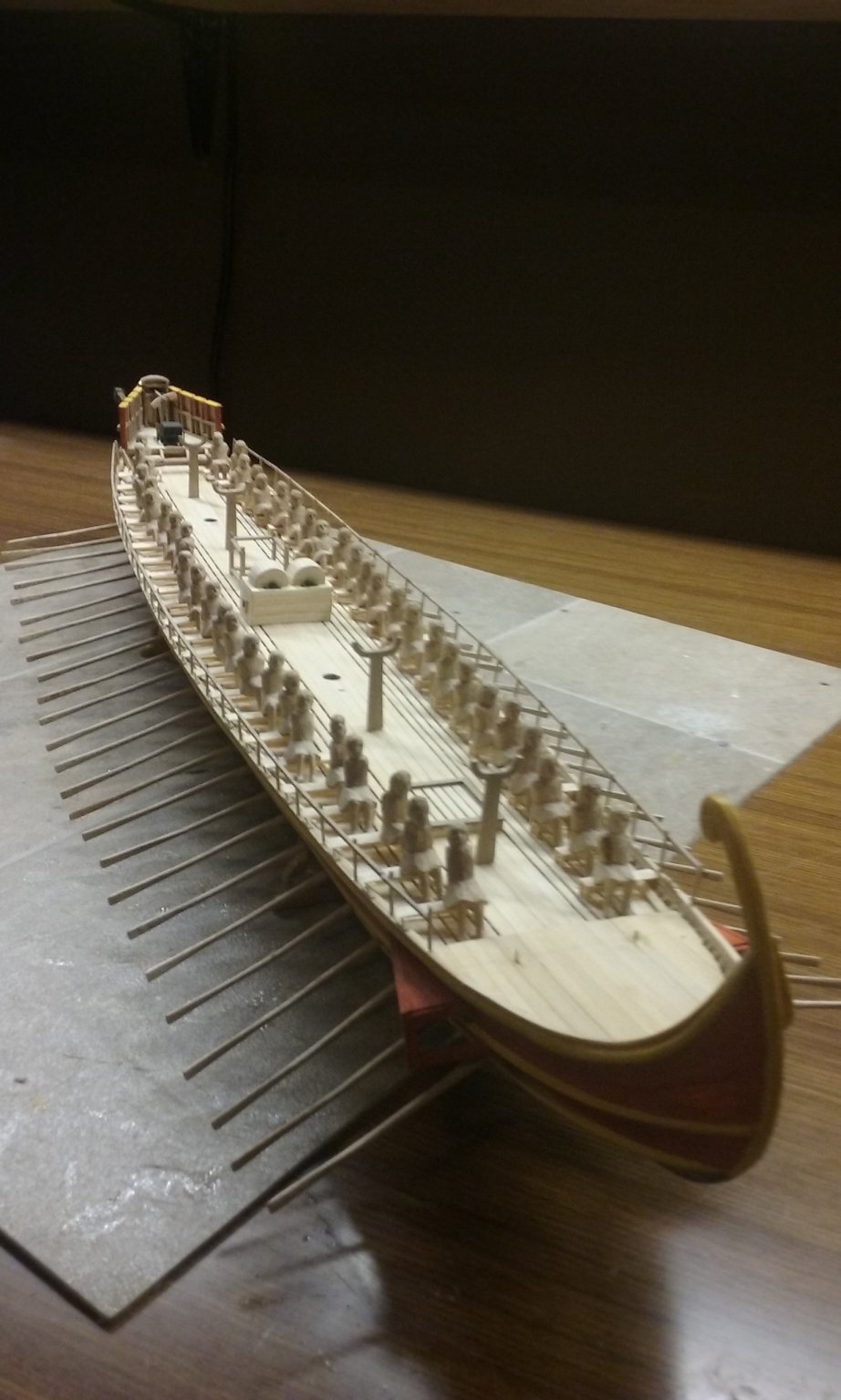
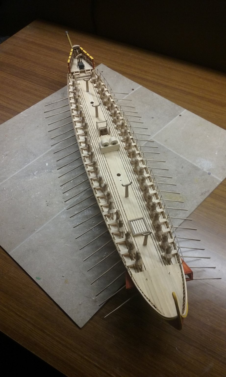
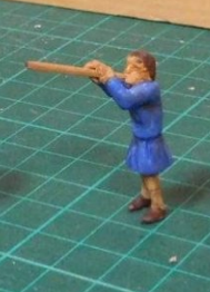
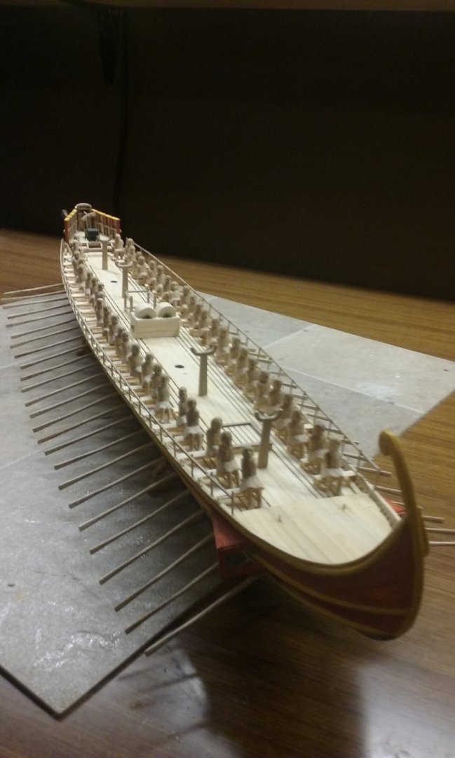
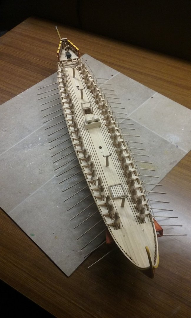
Oh, and you might like to put up some of your painted figures in the "Shore Leave" section of "The Crew's Lounge" (bottom of the Home Page), under "Non-ship/categorised builds." I for one am very interested in methods for painting human figures, particularly on getting the faces right. I have 48 oarsmen I have to paint for my dromon, and they're pretty close in size to your figures. Steven
-
Good to see this build log starting, Boxbuilds. I discovered the person I thought was a part-time volunteer at the Powerhouse Museum in Sydney, where there's an almost identical model, was actually at the Maritime Museum, quite a distance away. I've sent a message to a friend of mine who I think used to be employed by the Powerhouse, but that was quite a few years ago. I'm waiting on an answer. Might be of use - I'll just have to wait to find out. I'm looking forward to seeing your progress on this build. If there's any help I can give, please let me know. Steven
- 71 replies
-
- 1
-
-
- great harry
- henry grace a dieu
- (and 3 more)
-
Yes, Oskar24, disregard our lame attempts at humour. Maritime terminology is a whole new world and it takes a while to get your head around it, but bit by bit it does come. There are quite a few good dictionaries of maritime terms online - I rather like this one - https://www.oxfordhandbooks.com/view/10.1093/oxfordhb/9780199336005.001.0001/oxfordhb-9780199336005-e-48 - but of course (particularly when you're just starting out) you will look up a word and the definition contains new words you also have to look up. But persevere, it does get easier. And ask as many questions as you want. The people here are very helpful and will often give you better ways of doing something that save you a lot of time and trouble. Steven
-
Starting to look very good indeed, Jo. Steven
-
Ah, you mean the sharp end and the blunt end . . . Steven
-
By hand. I think a slip with a power tool could be disastrous. Takes awhile, but much less time than doing the carving. Steven
-
Not quite sure what that means - not even sure I want to know . . . Well the hands will be able to recover now. Oh, and to clarify, it's not that I kept cutting myself as I carved (though that does happen occasionally), but the heel of the left thumb gets painful, almost as though it's been bruised (it hasn't). Probably just holding the hand in a position it's not meant to be in for long periods as I hold the figures to be carved. Steven PS: I'm onto sanding the figures now - a little more than half way through.
-
That's a very clever technique. You're doing a marvellous job with this model. Steven PS: Where in Oz are you based?
-
Absolutely beautiful! Steven
-
We have a flute player The others may take some time . . . I feel like resting on my laurels for a while . . . Steven
-
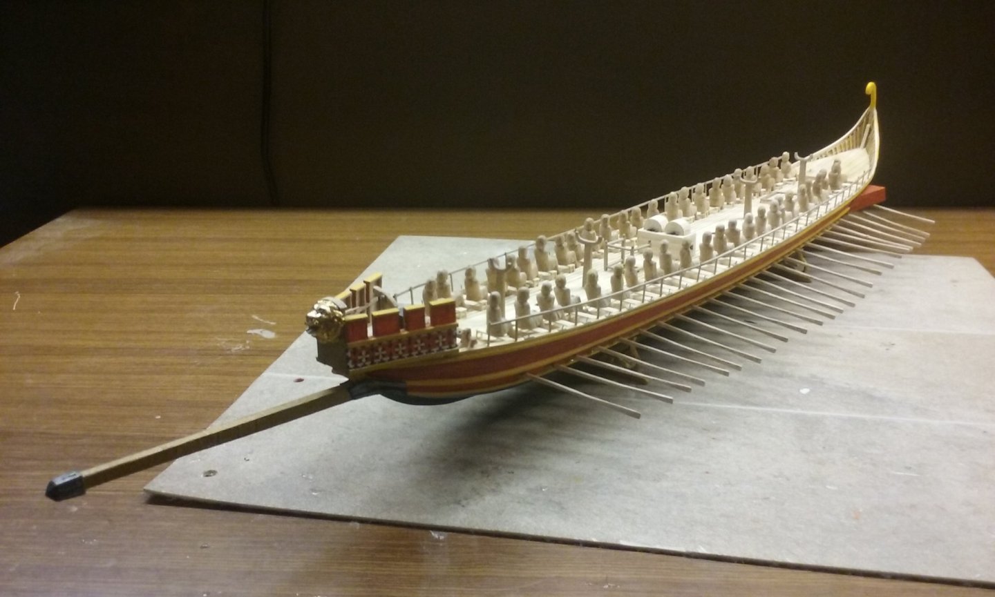
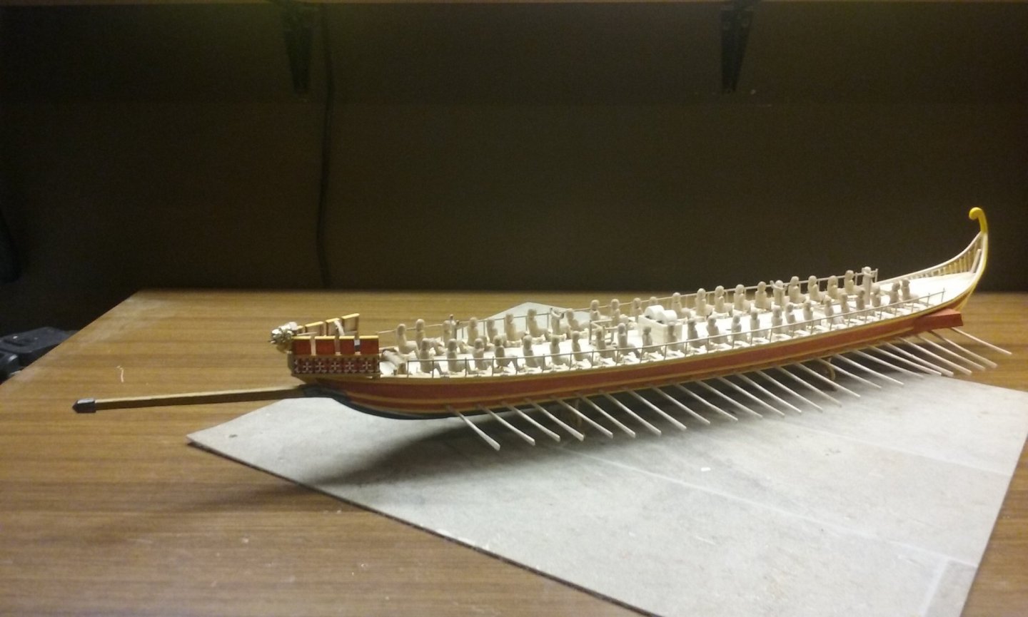
Pat, I was in the sea scouts when I was a kid but I still haven't mastered how to tie a bowline, let alone a sheepshank or sheet bend. I can do a reef knot, and a round turn and two half hitches . . . but I always had trouble with getting my head around knots. Now onto other things. A real milestone - I've finally carved the last of my oarsmen! But wait! (I hear you cry) they still need to be smoothed off and they don't even have arms yet. Crikey, you're a cruel bunch . . . Steven

-
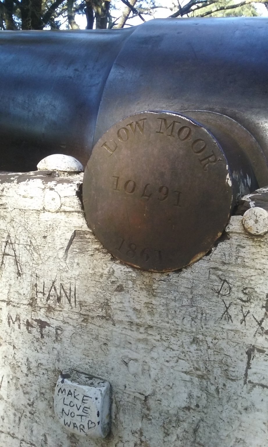
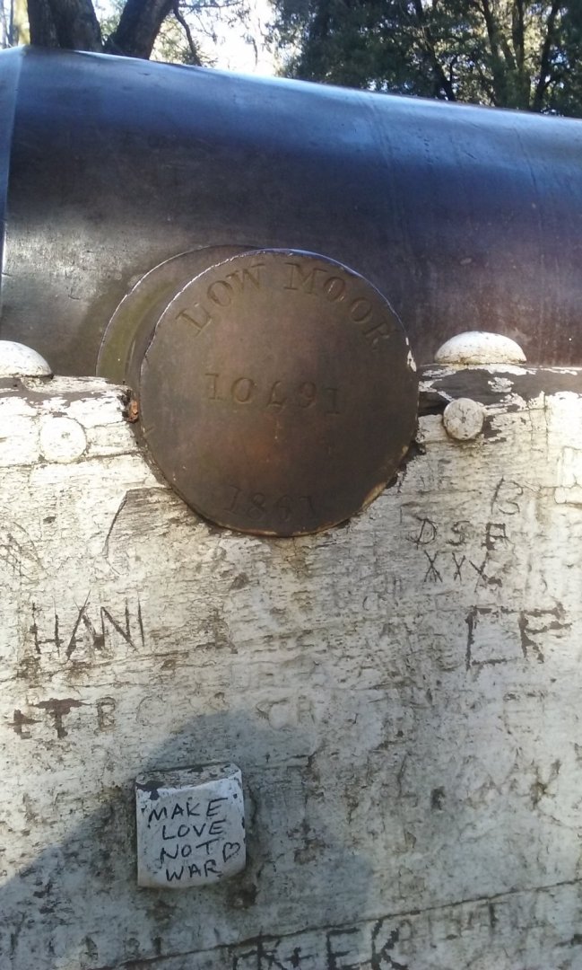
Thanks, Druxey. Unfortunately I didn't have a tape measure with me - otherwise I'd have been able to find out whether the gun was 8'6" or 9'6" long (much less usual). Steven
-
I went back to Wombat Hill, and sure enough there was an inscription on the end of one of the trunnions: And another (later)inscripton below it . . . Steven

-
By the way, at the risk of derailing the thread somewhat, I take it you're familair with the 1956 movie "Battle of the River Plate"? If not, much of it's available on Youtube, particularly the battle scenes. Steven
-
HDFC - I like it. I'll have to use that term from now on. (Thus speaks the man who, after the Battle of Hastings re-enactment of 2000 AD was known as H2K (Hastings 2000) - for the 2006 re-enactment coined the term TNBO -The Next Big One - which became the shorthand for the event among the re-enactment community. Of such things is immortality made). Steven
- 130 replies
-
- 2
-
-
- wütender hund
- hanseatic
- (and 2 more)
-
Welcome to the Dark Side, Chuck. I have to say I found the comments about the WH's forecastle interesting - they relate directly to a discussion at Maybe I need to re-evaluate some of my thoughts on this. If some cogs were indeed purpose-built as warships, the fact that some cogs had forecastles and "fortified" aftercastles while others didn't might be significant. And I'll be re-looking at some other contemporary pics from the 15th century with ships lacking a forecastle - perhaps purely merchant ships? Steven
- 130 replies
-
- 3
-
-
- wütender hund
- hanseatic
- (and 2 more)
-
Looking good, Jo. You're starting to get on top of hull planking, and every time you do another model you'll get better at it. Steven
-
Very nice work, Chuck. I'm enjoying following this build. Steven
- 130 replies
-
- 2
-
-
- wütender hund
- hanseatic
- (and 2 more)
-
Hi Slowhand. Looking good. You might find Cristiano's polacre buildlog helpful as a reference - https://modelshipworld.com/topic/7290-venetian-polacre-by-cristiano-finished-xviii-century-from-original-drawings/ Steven
-
Nice precise work Goetzi. The model is making good progress. Steven
-
Neither could I. It just might be missing - accounting for the titles every so often. Steven
-
I just came across this video with quite a bit of original footage of the Graf Spee: It might have some worthwhile information in it to helpyou with your build (sorry about the intrusive watermark). Steven