


Thistle17
-
Posts
1,042 -
Joined
-
Last visited
Content Type
Profiles
Forums
Gallery
Events
Posts posted by Thistle17
-
-
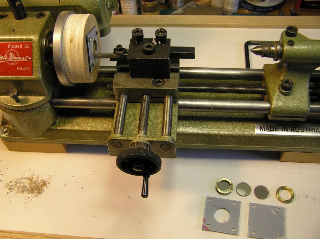
As they say the devil is in the details. With my limited experience with machining metal and other materials on a lathe or mill I was stumped as to how to machine the plexi-glass (1/16") to fit the brass portholes. Since there are 10 instances I was not about to hand cut them out and file them to fit. It occurred to me that the methodology shown in the attached photo might work.
On my Unimat I attached a 3/4" plywood secondary face plate to the Unimat face plate. To this I attached small squares of the smoked plexi-glass. Using my cutoff/parting tool that I honed to a very sharp cutting edge I slowly turned the plexi-glass to the proper diameter. It took 2 attempts to get the almost correct diameter. On my first pass the "glass" grabbed near the release point. Prior to the second pass I trued the plywood secondary face plate. So doing solved the grabbing problem. I did find that the plexi-glass melted a bit no matter how slowly I fed the cutter. Some finish filing addressed the rough edge and fit.
I was tempted to stack a few plexi-glass plates together to speed up the process but decided I was pushing my luck. Only 7 more to go!
Joe
- Roger Pellett, druxey, Seventynet and 1 other
-
 4
4
-
I have heard it said that sometimes the journey is more important than the destination. I wish you both a pleasant and enjoyable one. Do continue to post your combined work.
Joe
- paulsutcliffe, Jeronimo, jablackwell and 1 other
-
4
-
I think this thread can be most useful to many of us "wana be" machinists. I would vote keeping this alive.
For example I have to machine some plexi-glass windows for portholes approximately 14mm in diameter. I have a modeler's vertical mill that I thought I could use in conjunction with a rotary table but I just can't quite get there mentally. Or should I be using another method such as a fly cutter?
Joe
-
Yes we are still intending to build this model for the museum. We made incremental progress between March and today. A new mobile bench has been built and we finally started fairing the bulkheads. We are about 70% complete with the effort. As I commented before it still looks ragged in this state but I am sure once the skin is completed it will begin to look more respectable. The director of the museum has been collecting fittings and artifacts at the 1:6 scale that are just so realistic it boggles the mind. In later posts I will be showing some.
Here is the model mounted to a substrate with a stiffener shown within that has aided in sanding the bulkwarks. Drawings on the rear board (these are the Navy's drawings) are not to scale but aid in our build needs. We have drawing to the 1:6 scale that we reference for the model as well. As you will note lighting is less than adequate at this point so we will be working on that as well.
![IMG_0899[1].JPG](https://modelshipworld.com/uploads/monthly_2018_04/5ae11cdedaf99_IMG_08991.thumb.JPG.b76206325cb1a8d161a86274b9644a97.JPG)
-
I abandoned my Corel cross section of the Constitution years ago for the same reason Anthony states. It just didn't measure up to what one would consider a quality endeavor. This is likely to be a stellar offering and considering the barge success I guess I will have to pitch a tent curb side at your shop to be in line for this offering!
Joe
- fnkershner, AntonyUK, Chuck and 4 others
-
7
-
-
-
To my surprise and dismay the order I placed showed up in our post today. The surprise I never heard from them after 2 e-mail attempts. The order status was never updated after the order acknowledgement. What showed up was 2 of the 6 identical items assembled and the other 4 needing assembly. The web site catalog was quite vague about "assembly required". In total the order took 14 days from Canada to my home just across the border. I will make this my last purchase from this company.
Joe
-
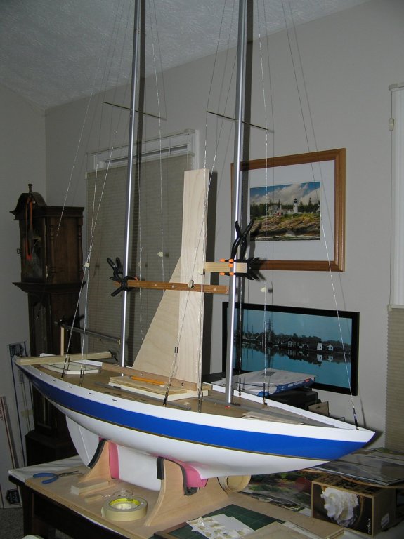
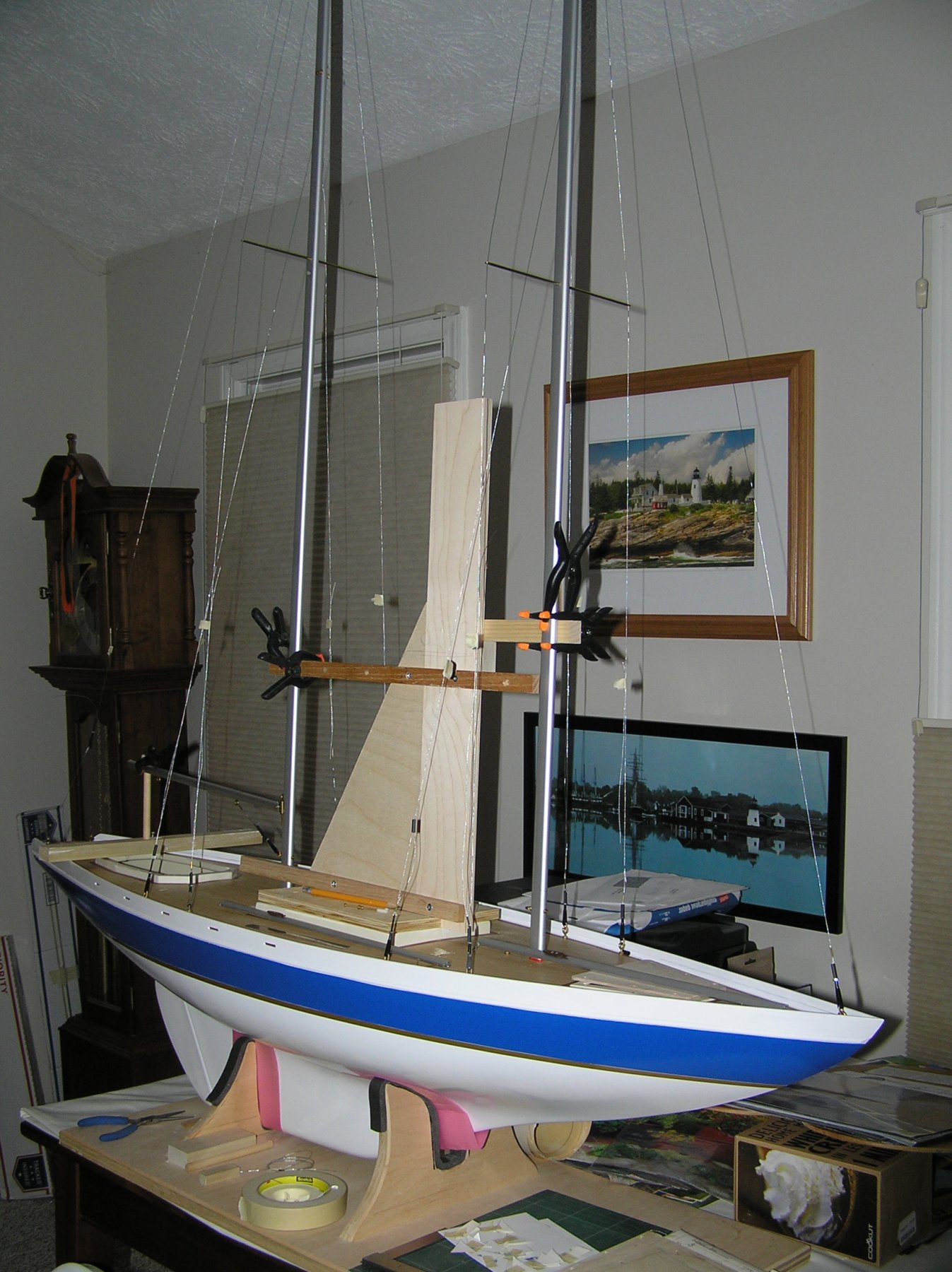
Looking back I observe that I raised the masts in February of this year. Now I have not been working this model full time but I certainly have put a decent amount of time in its advancement. Below is the latest depiction of its progress. As shown all sails are up and either tethered or awaiting to be secured. You will notice that the shrouds and stays, for the most part, are temporarily secured with miniature alligator clips. The reason for this is that I am unsure at this point if I should crimp the Du Bro fittings at the deck or wait until I deliver the model (recall I have to step the masts for delivery). Note that the wishbone is finally in place. Also note there is a temporary "spreader at the mast tops to maintain the mast vertical alignment in light of the temporary shroud and stay situation. The down haul rigging for the wishbone is not in place yet but will be as soon as I complete some deck bitts to tether all "floating lines.
As I progress I am reminded of a song lyric that goes "the ocean is a desert with its life underground". I offer that as I under estimated the task of converting this to a static model. Most of the operating rigging for this model is below deck. As an RC model most top side rigging is tied off close to its need or fed down below through small tubing cleverly disguised in deck appointments and ultimately secured to pulleys, cleats and the like. In addition, on modern sailing craft, there are few traditional cleats. Most are cam cleats which are strategically placed on cap rails, outcroppings of the hull or some other means. There is neither the opportunity to do so here or are there parts that I could use that I know of. Hence I must compromise, much to my dismay.
To move this model to completion, I have yet to trim out the deck furniture with glass simulation (smoked polycarbonate), and add skylights, grab rails and air vents. I have to add the stanchions/railings and aforementioned bitts. I also have to model the life boat which was missing from the parts I received when I took this on. There a few deck fixtures I have to address such as the anchor (which was to be glued to the outside of the port side of the hull) and the anchor winch which has to be fabricated. Might I say that the anchor placement authenticity is troubling me.
I will leave it there.
Joe

- Seventynet, hexnut, oneslim and 2 others
-
5
-
I do not know if any of you folk have attempted to do business with this company. I recently tried and am now suspicious, at best, about this operation. I placed an order recently after being vectored to their web site. I placed a small order and paid through Pay Pal. I did receive an invoice but I suspect it was computer generated. There was no indication that parts were out of stock. The invoice only said "Shipment Pending". I tried e-mail contact and received no reply. I then went to a Google Search and discovered that "Business is Permanently Closed". Several Google reviews mirrored my complaint. If one goes to the web site directly it is still active. I now have Pay Pal interceding.
If this is a valid business it certainly doesn't know how to treat customers! Either that or I am spoiled by the reputable businesses I deal with state side!
- mtaylor, coxswain and thibaultron
-
3
-
This is a bitter sweet tale you tell Barbara. The model speaks for itself but your being there by his side shouts out your love for him. We all should be fortunate to have a daughter like you.
Thank you for sharing. Press on and keep in mind that the journey may be just as important as the task. God bless you both.
Joe
- geoff, Barbara Lange, druxey and 1 other
-
4
-
It is nearly 2 weeks since my last post. I must admit that after hours of web search and doodling I have failed to come up with a decent rendering of what the mast attachment for the wishbone should look like and I might add something I could readily fabricate. So I have had to admit "defeat" and move on. Since the model is to be a static display I have decided to fabricate a simple fore mast clip that wraps around the mast's teardrop shape and gives some appearance that some attachment device does exist.
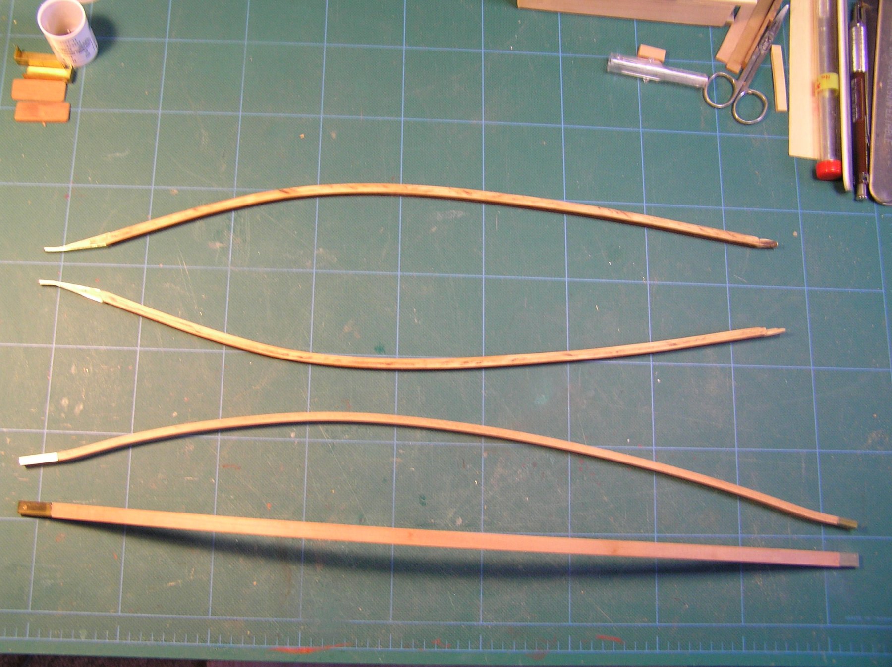
Pictured below are the remade wishbone elements. They are made of mahogany strips (2) and have been wet formed on a mold. The elements when dry were glued together and trimmed down to 5/16" X 5/32" dimension. To each end I have let in a brass rectangle tube (of the described dimensions) to give some realism to the elements. Note they are longer than the original wishbone elements supplied in the kit as they now will be attached to the mast and not the sail. I also had to ensure that the mast location for attachment did not interfere with the shroud lines fed down through the mast tubing. The left most ends still need to be tapered to conform to the mast cross section. I plan to do this with some mill machining and finish off with files. The members will be screwed to the fore mast/fashioned collar. The right ( free) end will receive appropriate rigging elements to (1) pull the sail taught and (2) facilitate both up haul and down haul rigging to keep the sail trim. Since all sails will be positioned along the keel I will avoid having to address the rigging mechanisms that would normally be required on a "reach" for the fisherman sail.
To some these compromises would be frowned on I am sure. However I have to take this path else the model will never get delivered!
Joe

-
Outstanding shop organization and at the street level to boot. I miss my old shop's access to that level. Your efforts will continue to pay off and responding to Michael Mott's comment about "at my age...." I would offer we are not pushing up clover yet so we all need to keep going! It's like a poster I used to see on the workout room at work. "There is no finish line"!
I am inspired by what you have achieved.
Joe
- mtaylor, paulsutcliffe and Mark P
-
3
-
Mike it is always a "tug" of what to buy and which version i.e. longer bed etc. My DRO mill has the 13 inch bed and I vacillated about the longer bed as well. It has not been missed. Recently I have been milling aluminum masts for the Atlantis and they are about 5 feet long. It is a bit awkward but I manage by adding a "rest" on the free end and moving the work piece (mast) along as needed in the vise, keeping the "y" position steady when I have to work over more than the bed will allow. Granted the things I am doing; drilling holes. milling a flat etc. do not require extreme accuracy. So at this stage of my usage I do not see the need for the longer configuration.
Joe
- Canute, Landlubber Mike and mtaylor
-
3
-
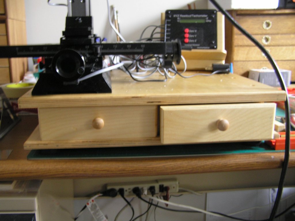
Mike I made a base with 2 drawers in it that store the smaller accessories. I find that on a crowed bench I am always misplacing, bits, the key for the chuck etc. It is worth the effort. Of course it does not hold the larger items like the tilting table but does hold the vise. My base for the mill is 17 1/2 X 14 X 3 1/2. The base has 4 rubber feet.
I have yet to work out a good system for all the cables as you can see.
Joe
- aviaamator, Canute and Landlubber Mike
-
3
-
The wishbone connectivity to the fore mast has become problematical. I am conflicted by the many versions of the fisherman sail I review on line. I have seen the sail rigged with and without the wishbone element. I have seen the wishbone attached to the (fore) mast and not attached. This is especially true when it is used as a boom replacement. Today I realized if I use the wishbone (it would be a lot simpler if I didn't) it has to pivot off the mast and has to have a mast attachment that will allow the sail to pass up and through the mast receiver. So now I have to attempt to come up with a form of mast yoke that answers both requirements. This is driving me a bit crazy. Here is a decent image of what I am troubled by.
- Seventynet, mtaylor and druxey
-
3
-
I think I have finally gathered the rules of wishbone rigging. I wish to clarify that wishbone "rigs" can apply to booms or gaff rig configurations. The whole idea of a wishbone is that it stretches the sheet and remains taught with force applied downward for it's use in place of a boom. For a gaff it also forces the sheet to remain taught and upward driven. In this case it does apply extreme force to the trailing mast top. It also creates additional stresses on the rigging in a jibe. For the same square foot of sail it purportedly offers higher speed under light winds. It is loved by some and spurned by others. It also eliminates the weight of hauling a gaff to its position.
As a result of a more focused search I have learned it is always fixed directly to the forward mast to which it is associated. The wishbone is tethered to the opposite mast with a down-haul line. It is or may be attached with an up-haul line (for trim) to the opposite mast. The sheet is hauled to it's position up thru the wishbone opening with a peak down-haul to the deck or mast. The apex of the inverted triangle sail is somehow tethered at the apex of the free end of the wishbone via another down-haul line I presume.
On this later point I will not add a down haul lineto this apex, but will tie it off as in the manner intended for the RC version of the model. I think I finally understand at least the basics of this rig.
Joe
-
I am getting to think I am over thinking wishbone rigging. Here is a recently found picture that depicts the wishbone attached to the fore and main masts, not the sail as the model would have me implement. Now I have to decide whether to live with the model implementation or change it over. Hmmmm!
Joe
-
I have to correct my previous statement regarding booms on stay sails. In searching the web last evening to get some idea how the wishbone was attached I ran across a ketch that had booms on both stay sails. My method to attach the booms will deviate somewhat from the parts supplied as they would not hold the booms in a fixed horizontal position in relation to the masts. A picture will be supplied.
I also came across a description of the tethering of the wishbone on a real craft that does not reflect the method for the Atlantis. I will have to investigate a bit further.
Joe
-
May I say that this type of rig i.e. the wishbone, causes me to pause and wonder why anyone would choose this sail plan in the real world. It is certainly not a one person sailer and I perceive it could be big trouble if weather turns foul in a hurry.
Having said that I have been ardently working the sails. I simulated the panel stitching with a #2 pencil and rule. The panel layout was defined on the sail plan and worked out reasonably well. Given that the sail material is a plastic, maybe even ABS film, with what appears as re-enforced fibers it was easy to layout the simulated stitching. A sharp #2 didn't work as well as a round point one.
The sail gussets were applied and the sails were fitted with the simulated rivets at each apex. The rivets were actually eyelets that had to be peened over. I did so by using suitable punches and final flattening via vise jaw crimping. The holes for the eyelets were made with a home made punch (dowel with a machined piece of copper tubing in one end). The machining was a simple chamfering of the tubing business end to form a knife edge. It worked well.
I am at the point of fitting all sails. I find converting to a static model with simulated hauling and tethering rigging is a bit in conflict with the original intent of the model. I do not wish to over state the issues but if you look at the picture on this page from 2/4 you will see that the sheets forward of the main and fore masts don't have booms. The model does and now I realize this is an artifact of the RC methodology of trimming them on a tack. The sheet ends can't "fly" on the RC version as the controls would have to be synchronized to haul in on one side and let out simultaneously on the other. So now I have to decide how to make them work with the static model as they just float at the sheet base and need some form of tethering to make them look convincing. Also I am trying to add working tackles to the sheet hauling works. Guess what; there are very few to be had out there at the moment.
I forgot to mention the main boom I discovered was too short by about 5/8". I cut it to the diagram length but at no time did I measure the length of the main sail at its base against the plan boom length. I again used a piece of copper tubing and CA glued it into the existing boom and attached the extension. Now the sail tensioner works correctly.
I am plodding on.
Joe
-
Jeff here is a suggestion that may help. Look on the The Nautical Research Guild web site under this sub text general listing. Hope this leads to a solution. Good luck.
https://www.thenrg.org/links-and-sources-for-the-ship-modeler.php
and right on this site under "someone looking to start a club in Palm beach". It is close to the bottom under Organization and Club News (parapharsed). I would have given you the direct link but it hung up my system for some reason.
Joe
-
Dave that is great methodology and ingenuity you display. i just bought some turnbuckles from a supplier and while they fit the 1:20 scale model they still looked clunky. Your method would have been a better solution. Thank you for sharing.
Joe
- mtaylor, BETAQDAVE, CaptainSteve and 1 other
-
4
-
Hello Kristoffer welcome to this forum. I am far from an expert modeler, especially when I witness the beautiful work herein. I reflected on your comments and self critique and smiled. I too view my work in a critical light and am probably my worst critic. I think that is healthy in a way. Your mind's eye is already calibrated to a goal of further excellence and you will grow as each project goes by. Its a learning experience and the "chase" is part of the fun. Keep going you have the right mind set. Welcome to MSW.
Joe
-
I have been spoiled by the high standards of today's instruction sets, especially those produced state side. I find that this model has caused me to retrench my work numerous times in part because of very poor instruction/guidance. I have rigged all stay and shrouds (but not soldered them or trimmed them) and have begun working the sails. They have required re-enforcement of the corners that are terminated as in real world sail making. Unfortunately the material provided was dirty and too small to use for all sails. Luckily I found material at a fabric shop that nearly matches the weight, color, texture and thickness of the kit sample. It is drapery liner. I have tried a number of adhesives to apply the cutouts to the sail but they peel off easily. I finally settled on DAP Contact Cement which can be applied with some precision.
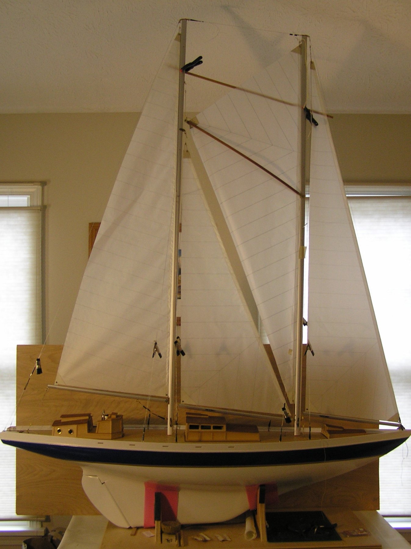
Once past this problem I began trying to fit the "Fisherman" sail and the Stay Sail between masts. I quickly observed that the sails do not fit neatly in between masts. Although the mast spacing is accurate (15 13/16 in apart) top to bottom the "Fisherman" has to be trimmed to dress nicely in between masts and the Stay Sail. To compound this the upper corner of this sail does not meet where main mast tethering is located.
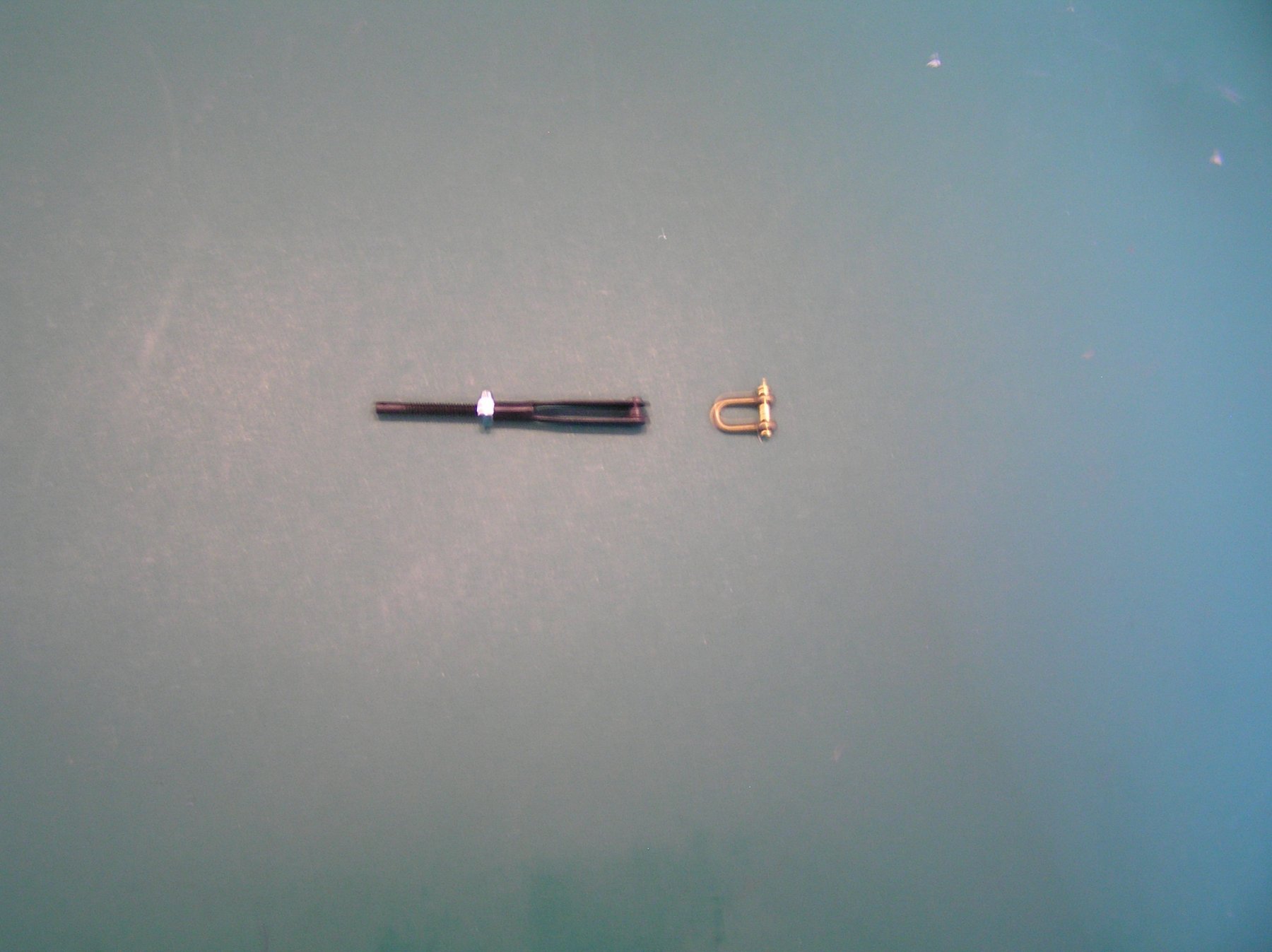
Luckily the combination of shackles and adjustable Du BRO fittings have saved me from an impending disaster. Pictured below are the shackle and Du BRO adjusters used. The second photo depicts the stage I am at. What is missing in the picture is the 4 foot step ladder I have to use to get to the mast tops!!!!!!
Joe

- mtaylor, druxey and Mirabell61
-
3

![IMG_0899[1].JPG](https://modelshipworld.com/uploads/monthly_2018_04/5ae11cdeb43e8_IMG_08991.JPG.1b5ea06d27c9597234c665be9c4520b2.JPG)


PBR Mark 1 River Patrol Boat by Thistle17 - FINISHED - Scale 1:6 - Model Shipwright Guild WNY
in - Build logs for subjects built 1901 - Present Day
Posted · Edited by Thistle17
In the prior post I had indicated there were some incredible scale accessories which we can use on the PBR model. In the attached photograph here is a sampling of the items. Note the 50 caliber machine gun with its associated ammo belt. Two of these are to be mounted in the forward gun turret. One will have to be slightly modified to change the "handedness" of the cocking mechanism. These should lend much interest to the final display for the museum.