


Thistle17
-
Posts
1,042 -
Joined
-
Last visited
Content Type
Profiles
Forums
Gallery
Events
Posts posted by Thistle17
-
-
Chuck, that was a really good explanation and now I understand the precepts of such an endeavor. I will continue to monitor the voting and participate when all decide.
Joe
- thibaultron and Canute
-
 2
2
-
Although I await the Winne from a personal standpoint I don't think it would be a practical "group build" from our club standpoint. If "group build" were interpreted at that level. Certainly at the larger meaning of "group build" as it applies to MSW it would be most interesting. I would add that not having participated in the Triton project maybe I have got the notion wrong.
I have been keen on a group project for our club as we have quite a cross section of talent and experience. I would like to see a more manageable project that holds the interest of the more experienced and yet is not a daunting task for the less accomplished. Why not a cross fertilization or teaming of talents? I am going to stick my neck out here. Here goes. For example, I have seen the drawings of David A's Hayling Hoy. It is a beauty. So here is a design, with a book yet. What is missing is something like a starter kit.
Before there is too much of an eruption let me say that I am only using this as a stalking horse. Maybe there is a nugget of an idea here. And then again maybe not.
Joe
- thibaultron, paulsutcliffe, MEDDO and 1 other
-
4
-
Rusty can you elaborate on the weathering powders use. I am not familiar with them. I see the "raw" resin castings. Then I see the applied castings. Is it a one step process?
Joe
- Jim Rogers, JesseLee, Rustyj and 3 others
-
6
-
Mike your work is not only inspirational but instructional as well. The collaboration between design and design verification is such a wise process, not well conducted by others. Thank you for leading the way. This is truly going to be a classic offering.
Joe
- Martin W, Canute, FrankWouts and 2 others
-
5
-
Vinne:
You neglect to say what you are building. That said, I suggest you look at some examples on this web site. Look at EdT's,Young America clipper starting at page 76 where he begins working the shrouds. Also if you look at the Syren's,Cutter Cheerful you will see not all shrouds are served completely. Hope this helps.
Joe
-
-
She is a beauty Ian. Mine is sitting on a shelf waiting for my attention once again so your pictures here give me a boost to get back into it. Lovely work.
Joe
- Seventynet, Canute and Jack12477
-
3
-
-
In preparing the lanterns for the main cabin I realized I had placed the reflectors backwards i.e. pointing the open area to the stern. These were corrected before adding the lanterns.
I experimented with painted wood lenses for the lanterns today. In the background you will see the stern lantern with a chock of mahogany semi carved and fitted in the lens area. It was convincing enough for me to abandon turning down the acrylic rod I originally intended to use.The wood infill was carved and sanded down and painted with Floquil colors and then coated with glaze.
I am now headed to the wood working shop to make a model stand and restart the display table. The model is quite heavy with the 45 pound ballast so the stand has to be substantial but not too over powering. I have made templates for the uprights and will cut out and assemble a full size model and try it out. I haven't been in the basement for some time and it is especially hard when the weather is so nice outside.
Joe
- druxey, Captain Poison and mtaylor
-
3
-
Welcome Mike! Do not be intimidated by this august body of modeler's feats. Let it be an inspiration and motivation to you. The forum is friendly and supportive all you have to do is ask. There are many reference books out there but your background in modeling will give you a good startng point.
The friendship sloop is a beautiful model and if you can get your hands on an out of print Time/Life book called The Classic Boat it will reward you with some fantastic pictures of a restored Jarvis Newman, Friendship called Dictator. I modeled a half hull of this vessel based on the coverage in the book.
Joe
-
Frank your work is an inspiration and to me as well as many others I imagine. Metal work is not one of my strong points so your detailed photos are quite instructional to me. If I haven't mentioned I am especially fond of skipjacks so it is a delight to follow the progress.
Joe
-
Thanks David I really appreciate your feedback. This project has not been without its problems and redo's. At first I was going to use the materials supplied but as the model grew on me I just couldn't use the cheap die cut kit parts. And as time went on and I got to know the client I had to deliver something worthy in honor of her late husband.
Joe
-
After nearly 1 1/2 years of time I can finally see an end point. Not that I have been constantly working on this for that period of time, mind you, but it does take effort to carve out time and then have the focus and what I call the head set to get things done. I am sure others have the same problem.
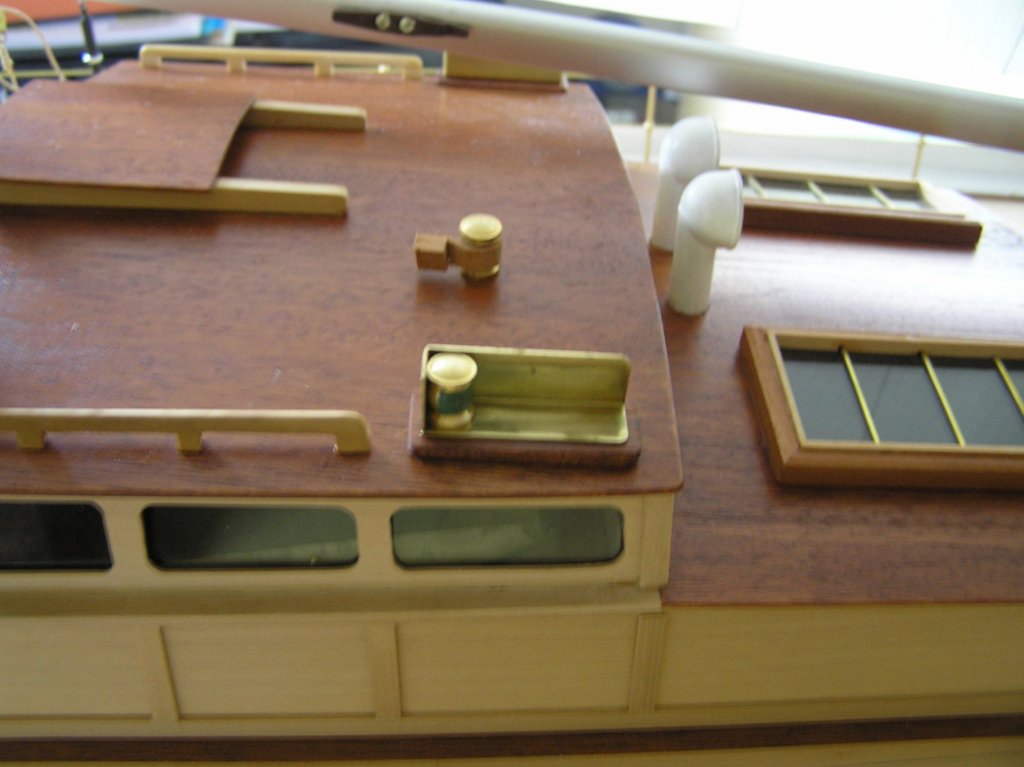
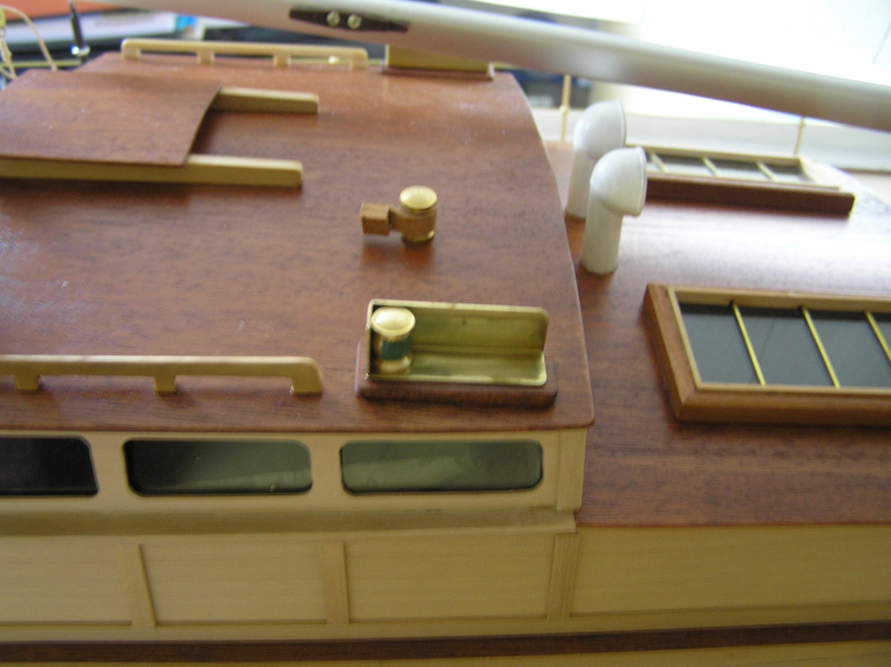
The first photo shows the "very close to finished" main cabin. Smoked grey plexi-glass has been installed in the larger windows, the grab rails were installed after fabrication on my vertical mill and the running light holders have been installed. The lanterns for these did not come with lens so the remaining task is to fabricate them. I have some plexi-glass rod that I am likely to turn down and cut to solve the problem. Oh yes they have to be painted (green and red). Even the seemingly simple tasks get involved. Hmmmm.
I think I stated earlier that there were no logical running rigging terminations other than on the main and fore masts cleats. That only provided 4 points of tethering. So I borrowed from another model of mine the notion of using bitts to tie off the remaining rigging. Note that all rigging is not terminated correctly nor is there any coiled lines attached. There is a reason.
I meet with the owner this coming week and we will ultimately decide on the method of transportation to its final destination. There are 2 possibilities; (1) step the masts and re-rig after delivery (that will require about 2 days of work) or (2) bite the bullet and get a suitable van to transport it fully rigged. I will tidy up the deck a bit and see what comes of the discussion.
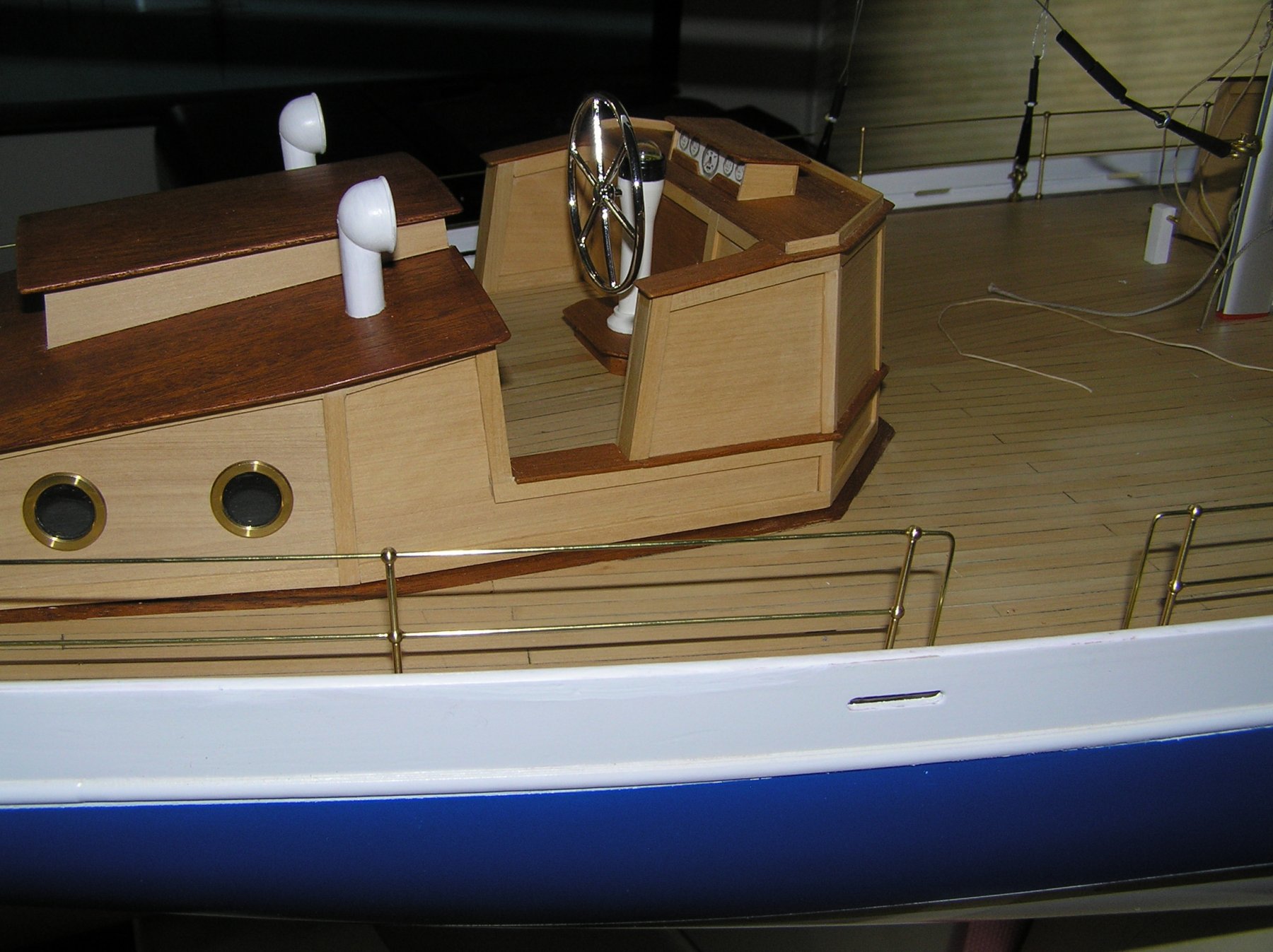
The second photo is meant to show the final result of the stanchion terminations. I had related that since the stanchions were screwed into the deck and aligned that feeding the brass railing wire through them and then terminating them into the deck was just not going to happen without some unpleasant results. So, as shown the upper railing were cut so that 1/2 of the upper stanchion hole was occupied by it. The other half of the hole was filled by a separate piece of bent brass rail that was terminated in the deck. I did not solder any of the junctions, rather I used thin CA applied with a micro glue applicator. It was surprisingly effective and neater than what I could have done with a soldering iron.
Joe
- Captain Poison, Jack12477, druxey and 4 others
-
7
-
Jason truly does a great job. We need to preserve and support Crown and Syren and I wish we could get Wood Project Source back.
Joe
- mtaylor, Landlubber Mike and Canute
-
3
-
Peter the mahogany planking was 1/16 for the model I built with my grandson. We used medium so we could move it around as its open time was about 20 seconds. Some of the planks needed a return fill with the thin as they just didn't lay down to our satisfaction near the bow. A slight application of the thin and finger pressure holding did the trick. The model is 2 years old now and there is no sign of separation.
I have also used DAP Rapid Fuse All purpose Adhesive to bond wood to ABS plastic. It is an interesting product as it can be gently removed and reapplied within 30 seconds of the first application. Afterwards it is fixed and cures in about an hour. I checked with DAP and the only thing you cannot do is glue ABS to styrene for example.
Joe
-
I have no experience with this filler but have used a state side product called RAGE auto body filler on a PVC skin for an RC model that needed fairing before it was planked with mahogany. Some of the filler was still present after sanding. I was timid for the same reasons as you. We finally plunged ahead and fastened the planking with CA glue and it worked. We used the 20 second variety. I might suggest that you make up a sample substrate wood/filler and try something other than PVA. PVA bonding requires penetration into both surfaces.
Joe
-
Barbara I sit in front of this PC and just shake my head at what is going on with you and your dad. It is so bitter-sweet. We have had 2 family members both with early onset of this disease. It was so painful to witness. Simple tasks became stumbling blocks for them. One has to show such patience and understanding to be a witness no less a participant. Your dad is remarkable as well. Be vigilant in his use of power tools. It is too easy to get in trouble even with modeling tools. God bless.
Joe
- mtaylor, Jack12477, Barbara Lange and 2 others
-
5
-
As Carl relates it is quite difficult to get brass to not round over when bent. As you did not state the thickness I have to assume it is less than or equal to 0.5 mm for your application. If you heat it, it will bend more satisfactory. You can use a small table top vise to crimp the fold and get better results yet. The combination of both should prove even more satisfactory.
Joe
-
Dave I am impressed with the jig making as with your model build. You invest well where it counts even if it may never be seen after the model completion. Great work.
Joe
- thibaultron and mtaylor
-
2
-
We just received a windfall of pictures from the folks at Patriots Point in South Carolina. They filled a request we had made for better detail pictures of the PBR they have there. For this we are truly grateful. Here is just one of many showing detail that is not on our drawings from either the Navy or Maryland Silver.
Update 5/14/18: After our meeting this week and a review of the recent photos sent to us we have concluded that we need to sort out the configuration of the model we will ultimately build. We realize that there were so many upgrades in the field that we have to settle on some base line and proceed from there. To that end 2 of our members are putting together a library of photos from on line and Patriots point sources to decide on the final configuration. It is all in the details for example the guns shown. There are at least 3 versions: a dual set close together, a dual set as shown and a single barrel version. This decision was easy to make. It will be as shown. However other subtle changes have to be accounted for elsewhere.
![DSC_3296_preview[1].jpeg](https://modelshipworld.com/uploads/monthly_2018_05/5af207c063a82_DSC_3296_preview1.thumb.jpeg.8820c1d07c3bb41111aae8b6a8f23330.jpeg)
- Canute, G.L., Geoff Matson and 3 others
-
6
-
I have been following these threads of "technology" introduction into this wonderful hobby/art form. I am also a woodworker and have seen the same thing happening there. Tonight I attend a "Period Furniture" SIG and the topic is on a newly acquired CNC vertical mill with attendant new software for design. One product this individual makes is a wooden bench vise screw, a very complicated part. I find this all so fascinating. My background is in real time machine control but I find myself fighting what I perceive as a "tension" with these new technology introductions into any of these pursuits. Where do I spend my time is probably at the heart of the tension as I am beginning to realize I am not immortal. Do I spend my time at the computer or do I spend my time at the bench?
How do you early adopters feel about it?
Joe
-
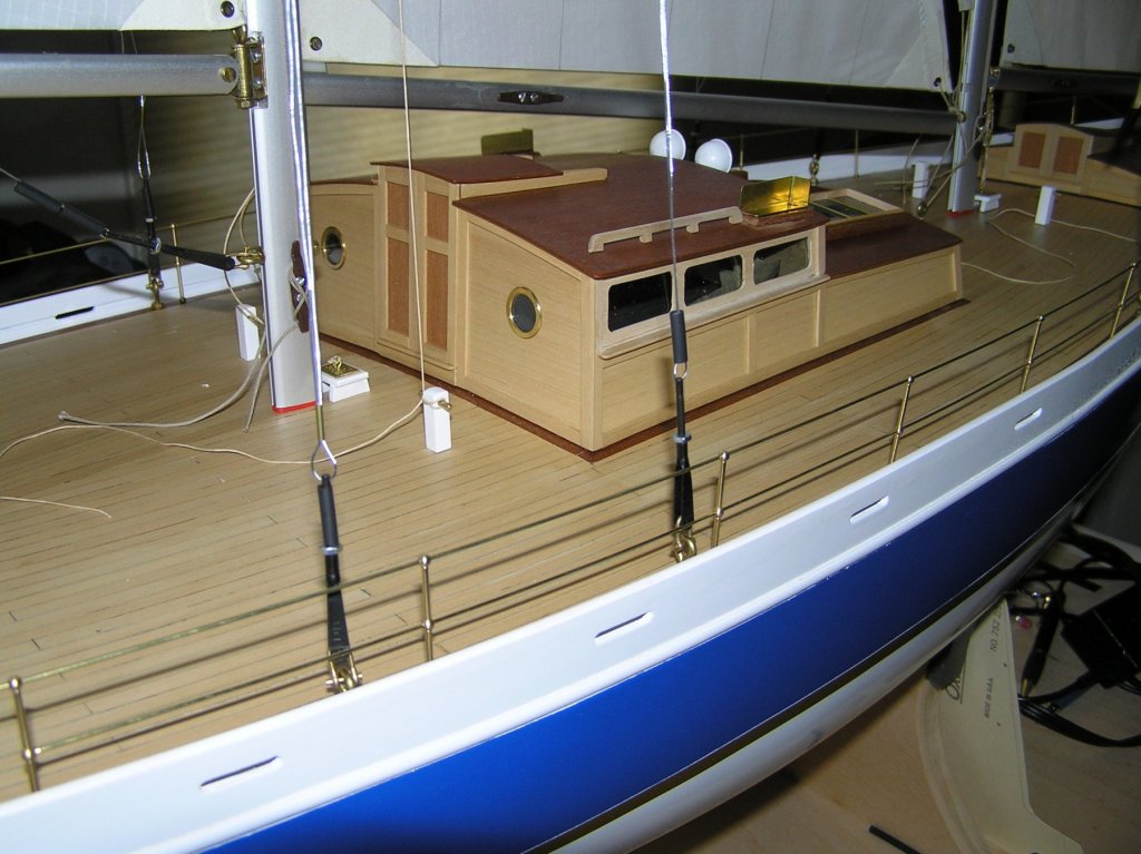
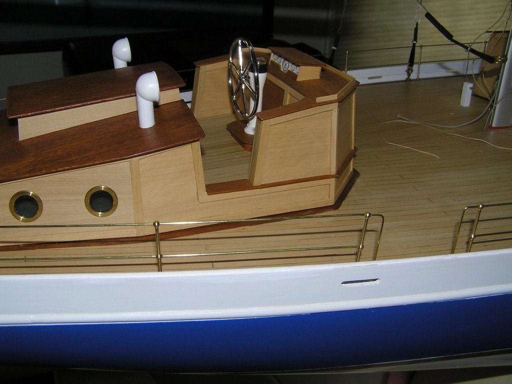
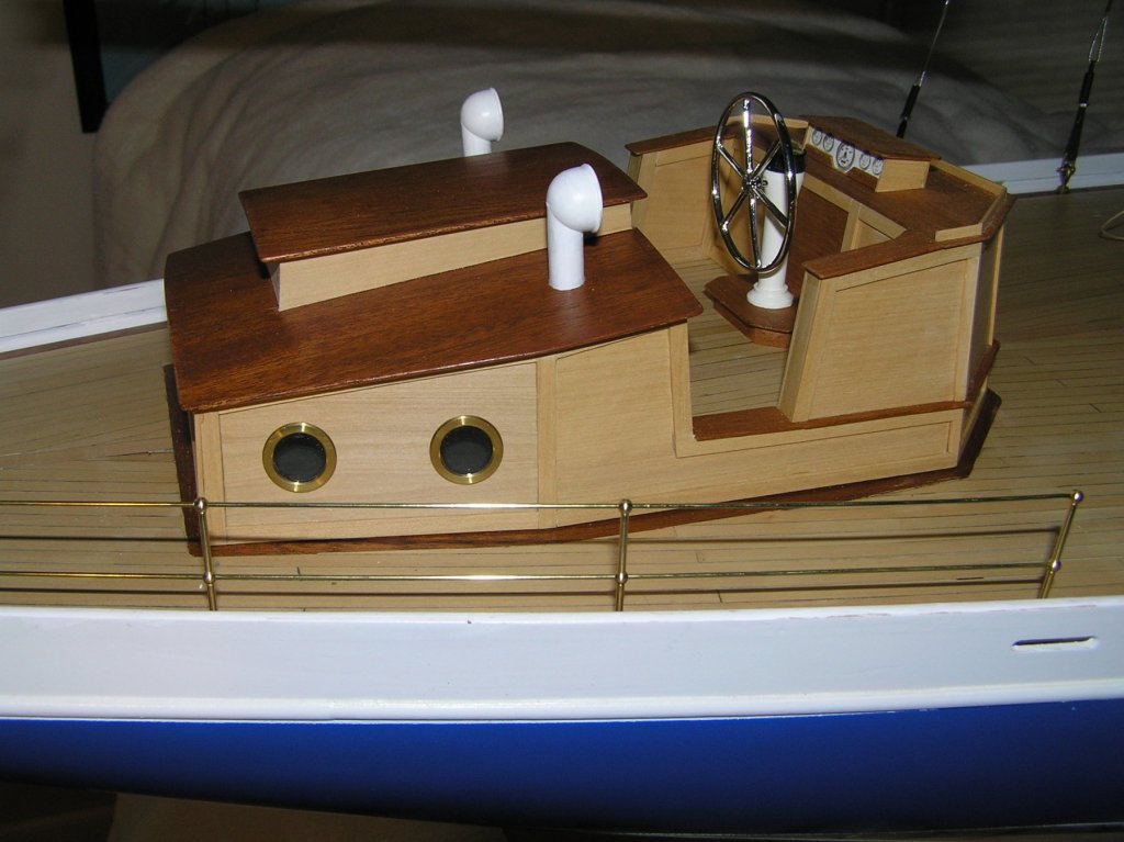
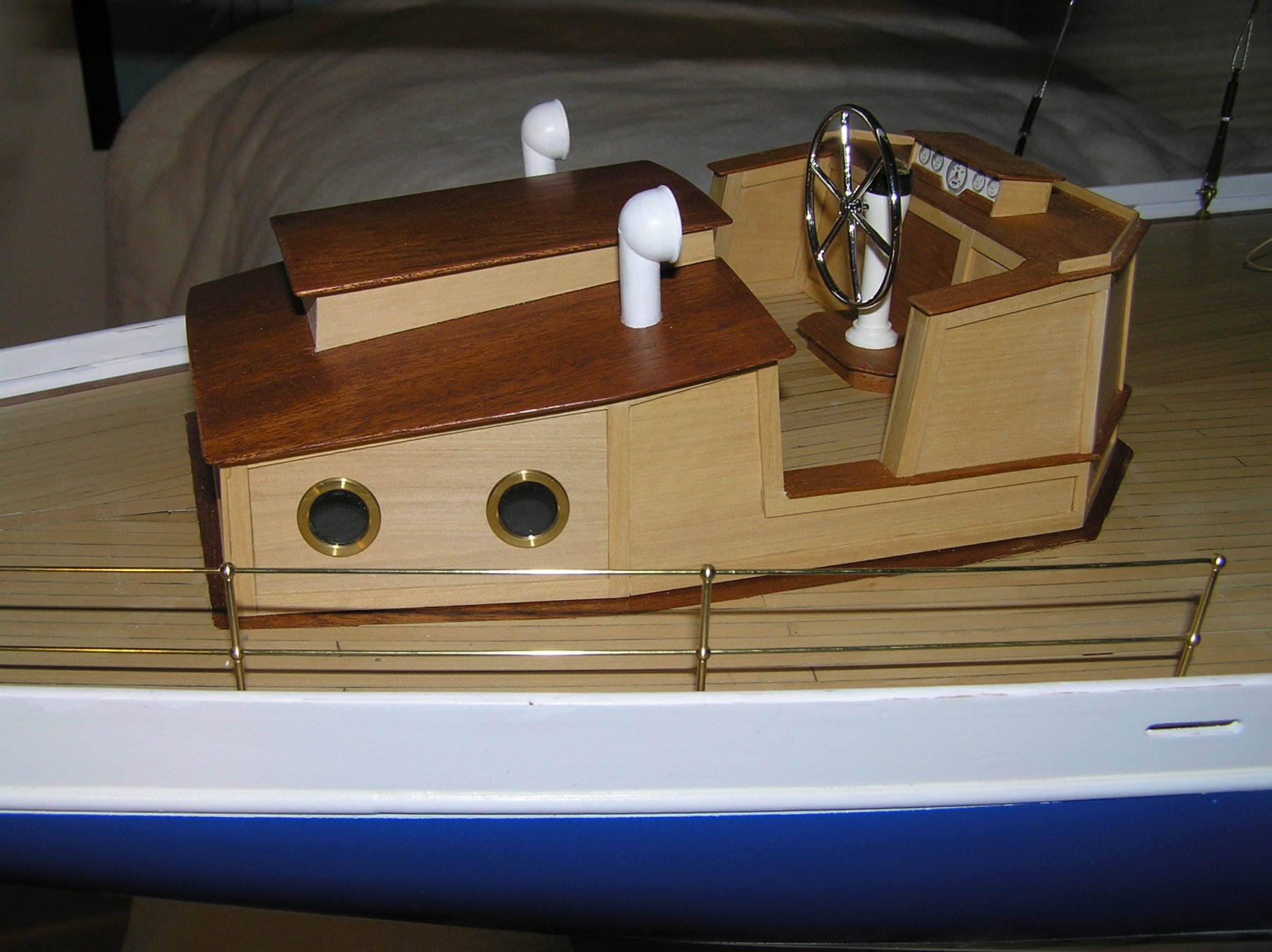
Detail continues to be added to the model. All portholes, with glass, have been installed. Ship's wheel and vents also have been added. The last remaining element for the aft cabin is to fabricate and install the grab rails. The first segment of stanchions has also been installed but not completed. I tried to fabricate the entire top grab rail in one piece but was unable to install it to my satisfaction.The stanchion post holes were drilled undersized so that the threaded base of the stanchions would screw into the deck for a snug fit. Doing so limited my degrees of freedom for fitting the forward transition element of the top rail into the deck (something like the aft termination). I had to cut the top rail off mid way into the top hole of the forward stanchion and will solder the mating (cut off) piece into the stanchion to achieve the end point.
I discovered a new tool (to me) that has helped cut the brass rails. Previously I was using a typical side cutter to cut the thin brass rod. It leaves an irregular end that is splayed a bit making it difficult to pass the wire through the stanchion holes. I ran across a costume jewelry cutter that has a 'chisel' cutter on both inside and outside edges of the cutter (unlike my side cutters). It produces a much cleaner cut off and easily passes through the stanchion holes.
Joe
- hexnut, Roger Pellett, druxey and 1 other
-
4
-
A number of our group have seen Rusty's model of your first version. It was a delight to behold! So this version should be nothing short of spectacular and a joy to build with your continued refinement of technique. Now the big question is how long do I have to stand in line to buy one??????
Joe
- Chuck, maddog33, FrankWouts and 1 other
-
4
-
Today marked the beginning of hull planking. You will note two sheets of (3" X 24") bass have been applied at the waterline (one per side). We have let them run "wild" at the transom as that framework is being developed "off line". This should be integrated at our next build session. The hull shape enabled us to use whole sheets of bass at this point and we will continue to do so until the area defined by station #4 - #5. This starts the more extreme curvature and includes the chine area that is above the waterline. The model spline is the height of the boat floor (minus the deck plating) and that will be added in all the way forward to the gun turret.
The bow area as we see it now will be filled in and sanded fair prior to advancing planking to the bow.
Of note are the full size drawings mounted behind the model which will definitely support our continued model build.
Joe
![IMG_0933[1].JPG](https://modelshipworld.com/uploads/monthly_2018_05/5ae9ec88094e0_IMG_09331.thumb.JPG.3f9816fcc97d7d9e6f6eec5fffdc5bd2.JPG)

![DSC_3296_preview[1].jpeg](https://modelshipworld.com/uploads/monthly_2018_05/5af207c044719_DSC_3296_preview1.jpeg.24af50c03390aa1ca503b1dd3bfe34d1.jpeg)
![IMG_0933[1].JPG](https://modelshipworld.com/uploads/monthly_2018_05/5ae9ec87d6ac1_IMG_09331.JPG.db4f604670f0aa661ddf6c272d966dfe.JPG)
Hello from Croatia
in New member Introductions
Posted
Ivan is this not an amazing venue for modelers? By the responses so far you have reached out to nearly the other side of the world. Welcome and very nice work on the plastic modeling. If you have not touched base with the IPMS (plastic modelers) do so, many are in your league. We have a chapter here, near Rochester NY.
Joe