


michael mott
-
Posts
5,195 -
Joined
-
Last visited
Content Type
Profiles
Forums
Gallery
Events
Posts posted by michael mott
-
-
Thanks for support and comments.
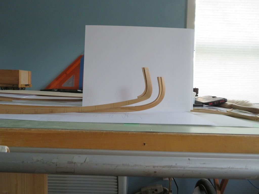
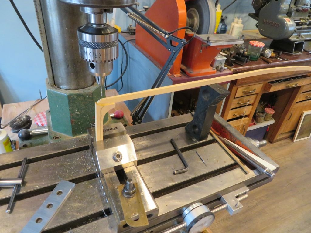
I did some tests today for the ribs (frames). When we lived at the lake we cut some and purchased some Birch firewood A couple of the larger split logs were really clean and straight grained so I split them up a little more and prepared some 1/4 cut billets that were approx 1 inch x 2 inch x 12 inches long They have been drying for about 5 years now so today I cut one up into 1 1/2" x 1/2" scale ribs (3/16 x 1/16 actual)
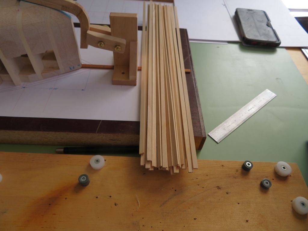
I had done some bending tests with other woods as well, left to right Birch, Yellow Cedar, Castello, Maple, and Beech. The air dried Birch bent the best.
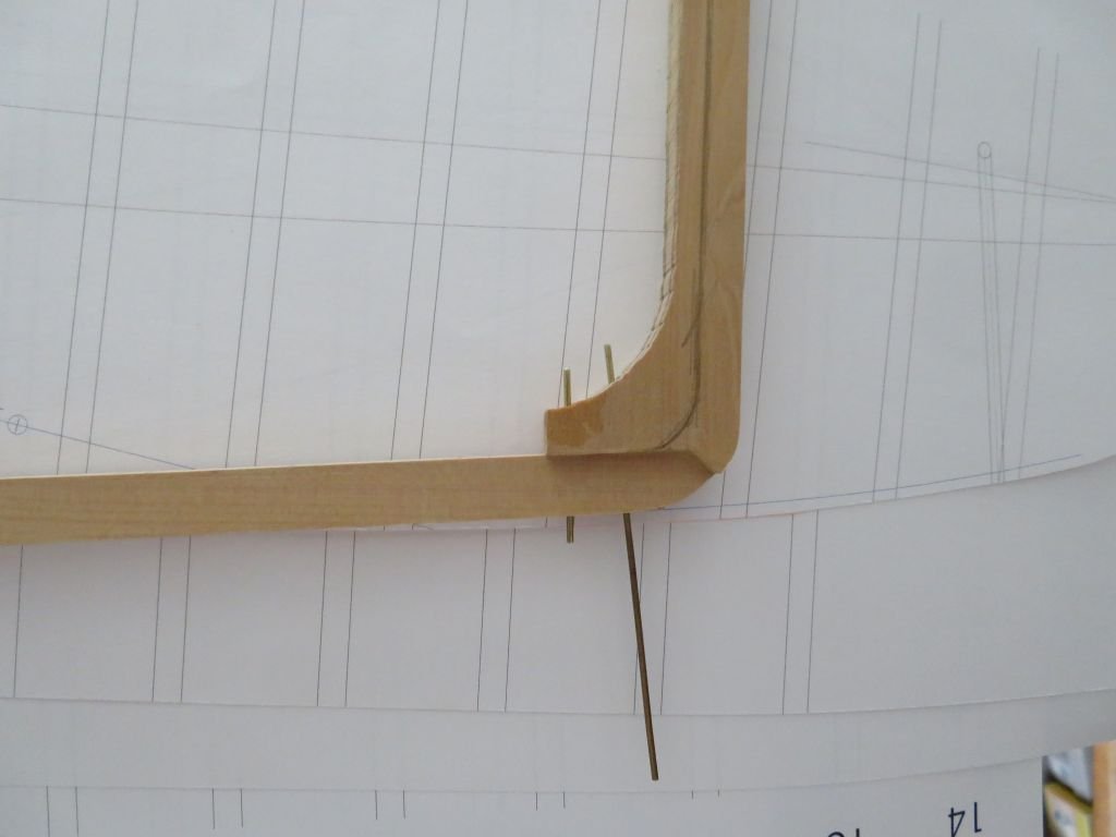
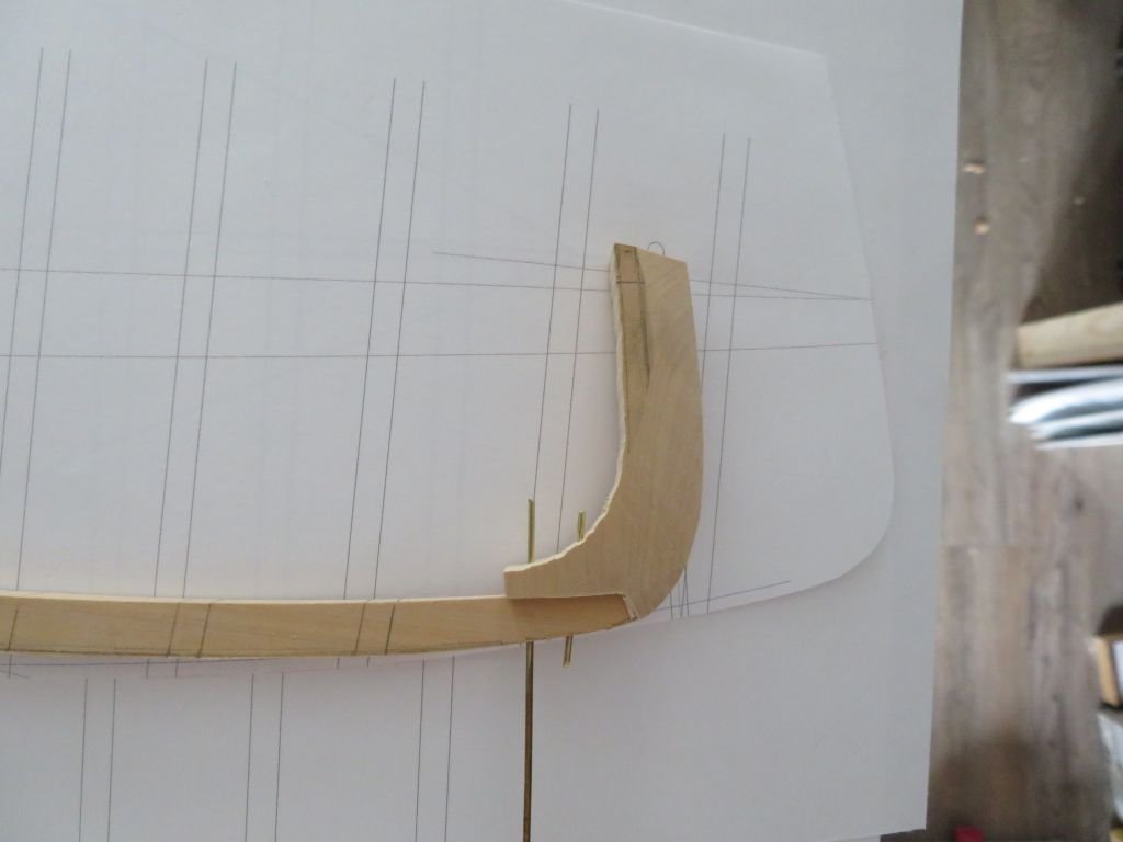
So a couple of test bends on the form to see how they are overnight. I wrapped the frame in a wet paper towel and popped it into the microwave for 1 minute then used the hot air soldering station to add a little more heat as I bent the frame in the bending jig before pinning it to the form.
These are just some preliminary tests.
Michael
-
Mark, thank you for the detailed explanation, that helps me understand the nature and size of these little carvings.
Michael.
- Keith Black, EJ_L, mtaylor and 2 others
-
 5
5
-
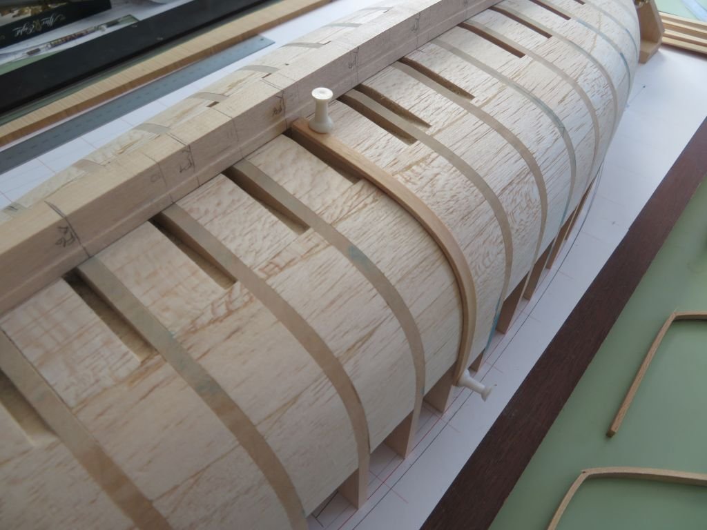
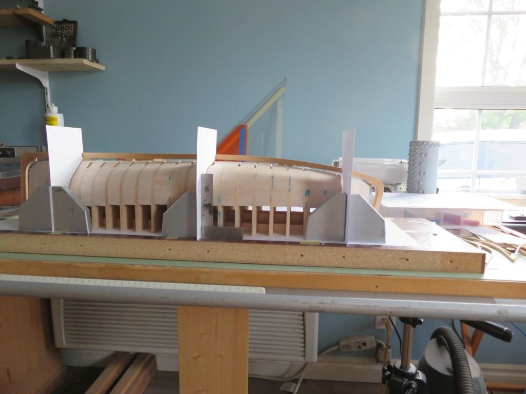
Had a chance in between a few other commitments to get the new clamps made and mounted, I also remade the location strip in order to align the clamps, and so did up a new print while I was at it.
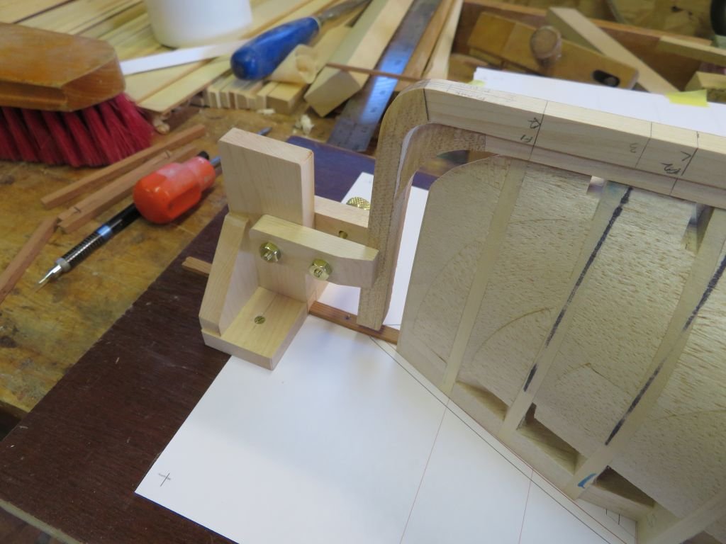
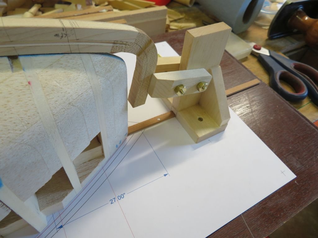
Now I can finish the rabbet and get on with the frames and floors.
Michael
-
Well said Bob.
Michael
- Hubac's Historian, mtaylor, shipman and 5 others
-
8
-
The carving looks good Mark How are you holding the small angel as you carve?
Michael
- EJ_L, FriedClams, Keith Black and 2 others
-
5
-
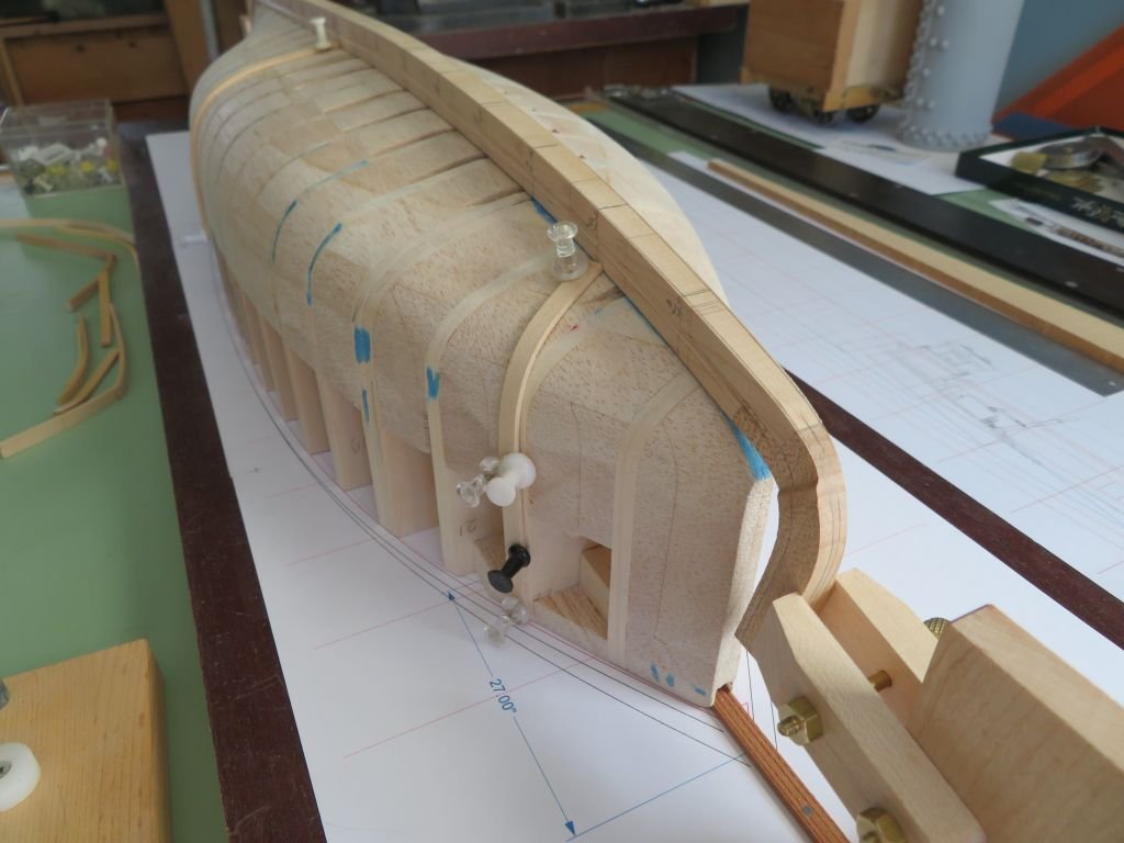
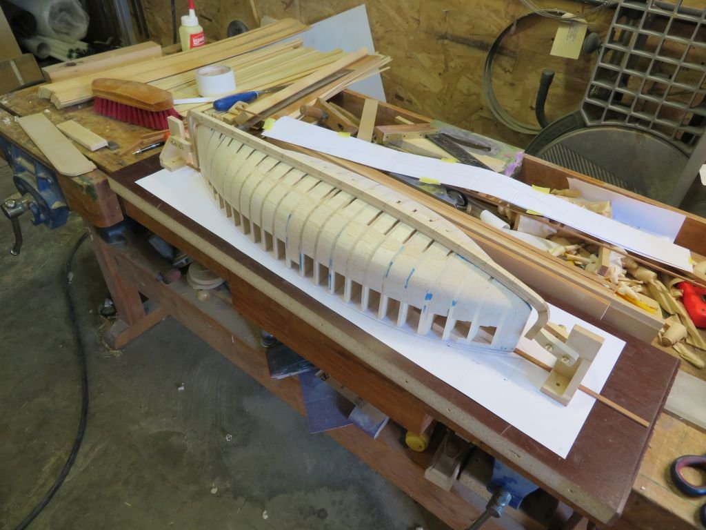
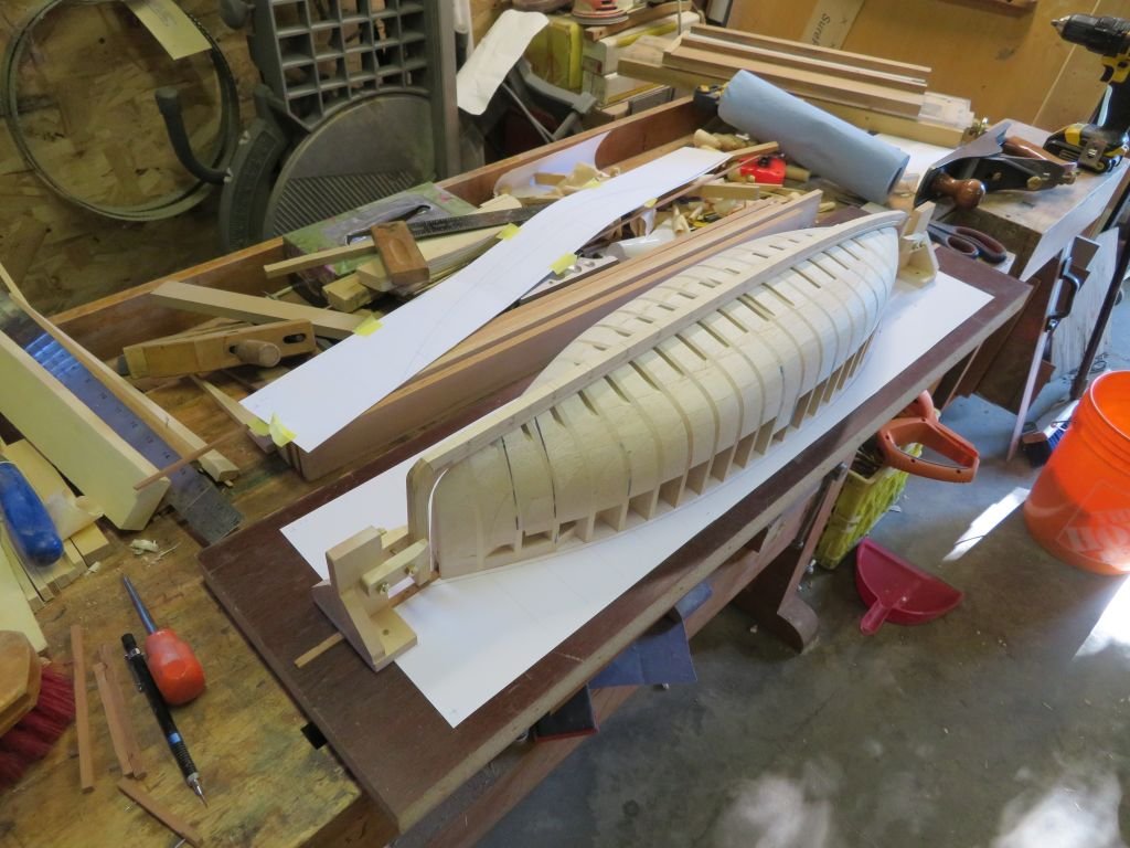
Continued work on the rabbets.
I am going to make a couple of clamps to hold the keel in position while the frames are shaped and fitted there are 15 frames in all so when it comes to adding the floors I will need to cut the slots in the base form. Nothing will get glued until the frames and floors are sorted. The Maple is a little more difficult to work than the Castello, but I am pleased with the results so far.
Michael
Michael
-
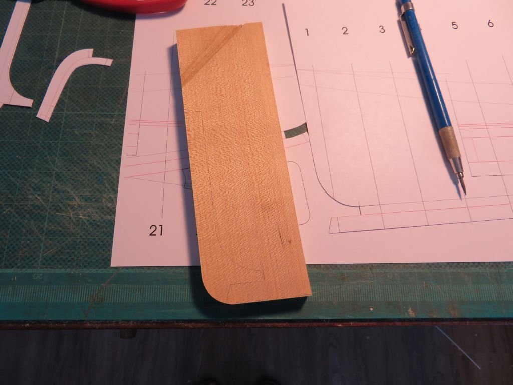
I began the slow work of carefully carving in the rabbet A big thank you to Druxey for comment about the rabbet following the line of the hull less the planking, and to Mark Pearce for the comment about the thickness of the wood at the stem. Obvious to many of you who have built several or more models of boats and ships, but was not to me.
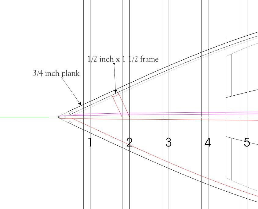
This time I have left the bow at the full dimension of the mid-ship as 3 inches and am working the taper down to the given by Roger as 2 3/8 inches just aft of the bow proper to allow for the clamping while carving.

I am following the templates for each station point along the new keel, and checking it with a small piece of 3/4 inch plank to ensure that the plank fits properly at each station. I am confident that this time I will achieve the results I am looking for.
Once I have the rabbet cut the whole length on both sides I will finish shaping the bow and stern posts.
Michael
-
Looks like you want to get this finished before next week😉
And I have not forgotten the bit O' wood I promised you.
Michael
-
So the keel gods spoke to me in a dream (that's my story an' I'm sticking to it) Turns out that they were not happy about using the foreign exotic wood called Castello.... I know it is a beautiful wood to use and work with. However they suggested I use some of the Maple that I cut from the 24 inch log way back in 1976 and that has been thoroughly air dried for the stem and stern
and the nice piece of rock maple that was in the storage for the long part. So I agreed
Michael
-
-
Beautiful work Druxey!
Michael
- Keith Black, druxey, thibaultron and 2 others
-
5
-
Hi Druxey, Thanks, I have come to basically the same conclusion. I am also guessing that this boat was built over forms with stringers then frames bent to the stingers and then planks to the frames and the stringers removed as the planking proceeded. funnily enough that was my first planned way to build this model.
Michael
- BANYAN, Jack12477, Keith Black and 4 others
-
7
-
1 hour ago, dr_huckin_john said:
Micheal, wondering what software you are using to do your design on?
Hello John, I am using Corel draw X7 because it is easier to generate curves than mu old Autocad 2000lt.
Michael
-
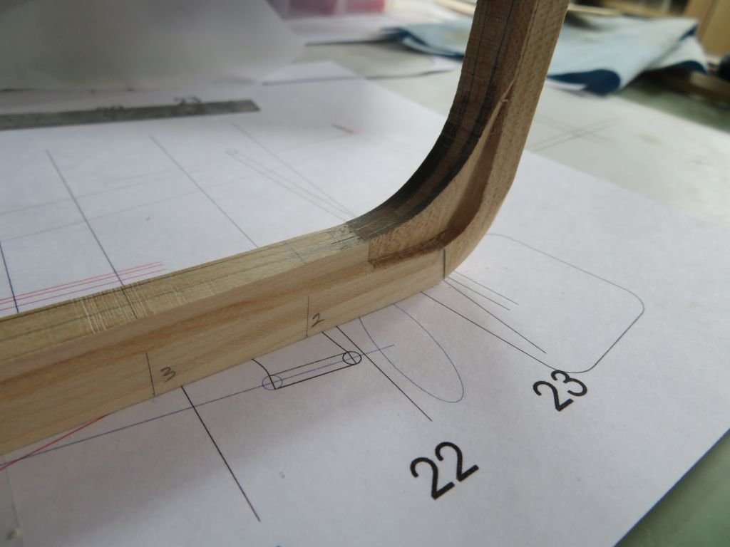
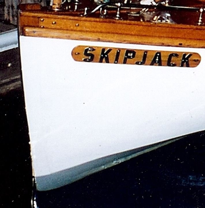
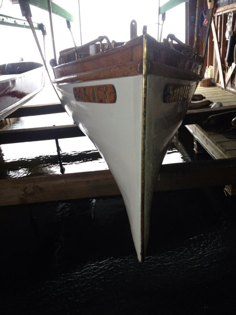
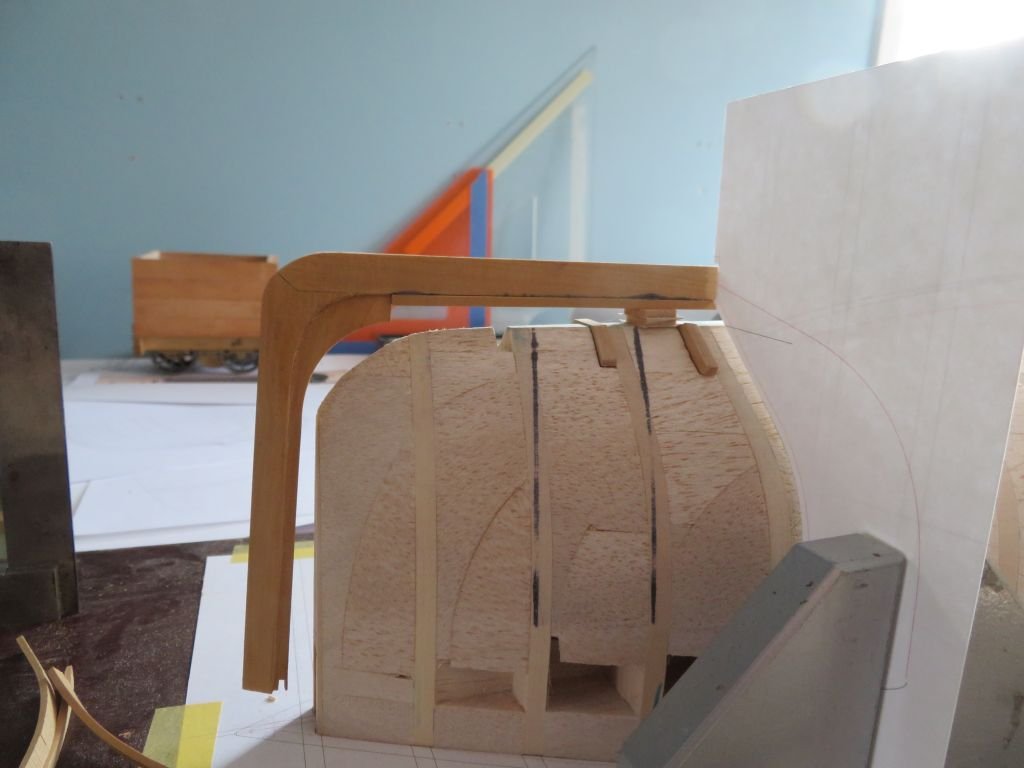
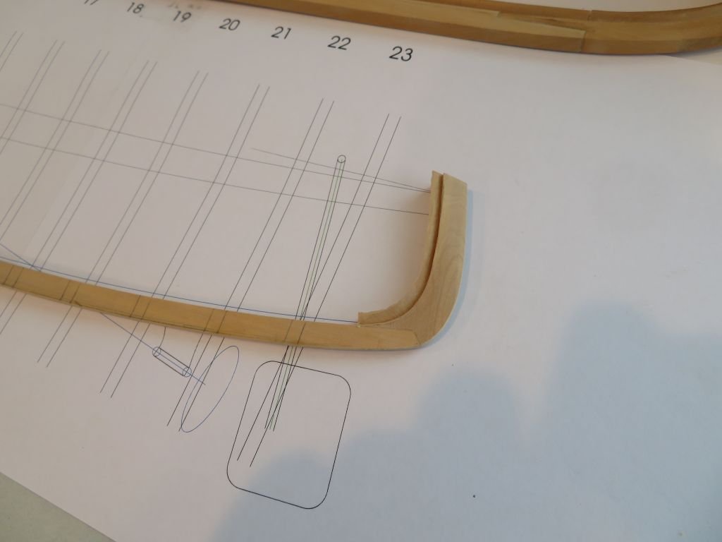
Here is another picture of the bow from inside the boathouse.
I think that one of my problems has been with the placement of station lines and the conjectured placement of the frames at the bow. and thinking that these are one and the same.
I have been trying to reconcile a frame at position 1 and am beginning to think that I have this all wrong it makes more sense that the first frame would be at the place I have marked as 2 in this plan view
Michael.
- mtaylor, G.L., Keith Black and 4 others
-
7
-
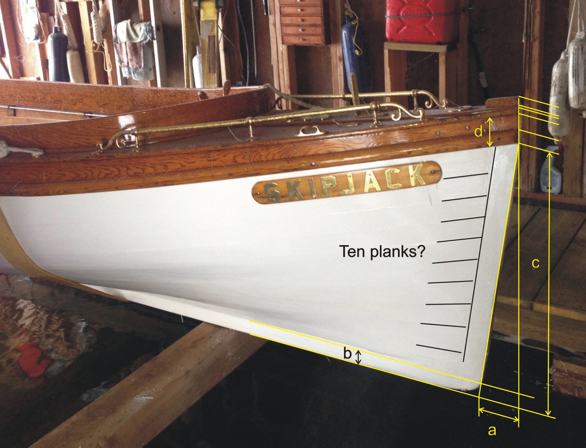
Hi Mark I think I understand what you are saying here is a different picture and the information that Roger gave me way back in the year 2014
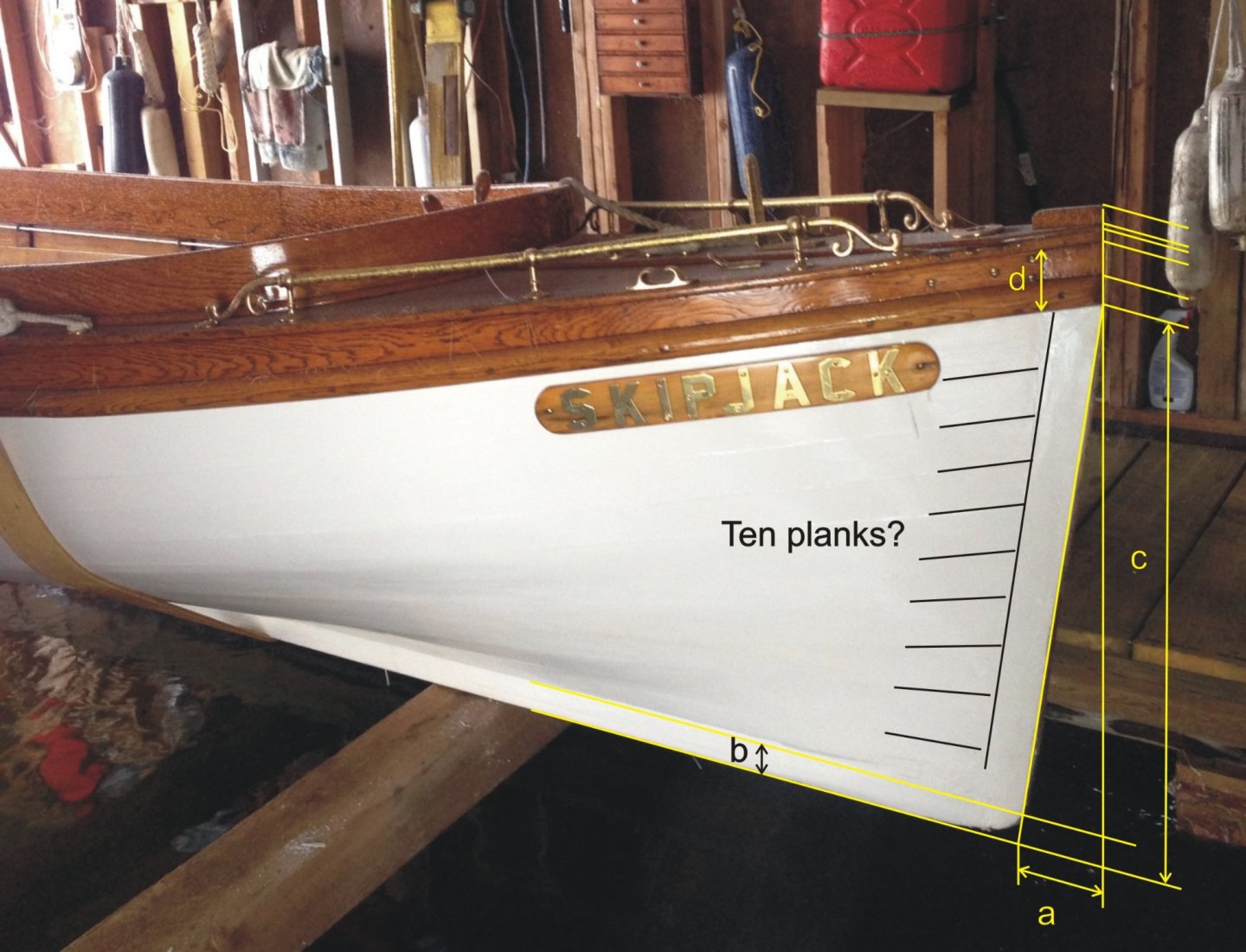
a - 3 3/8
b - 3 inches deep x2 1/8th at the bow 2 inches x 1 3/8 at the stern
c- 31 inches at the bow
- 38 inches at center
- 15 inches at stern
d- 3 inches at bow
- 5 1/4 at midship
`
There are ten planks
All the other dimensions that I have are taken from inside the cockpit ie length of open cockpit width of cockpit height of coaming ,seats etc
regards Michael
- Ryland Craze, Keith Black, mtaylor and 3 others
-
6
-
1 hour ago, druxey said:
Visualize the rabbet as the outside shape of the boat, but less the planking.
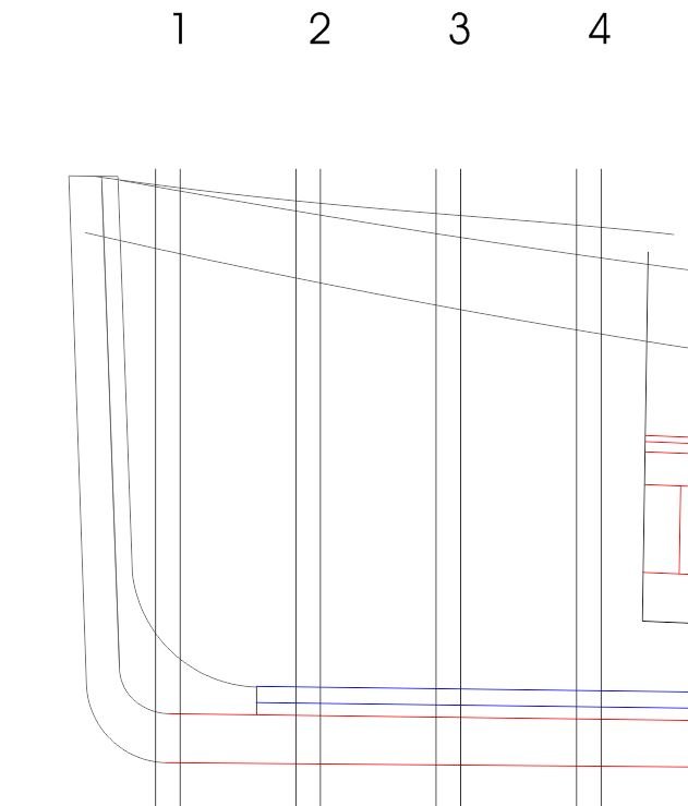
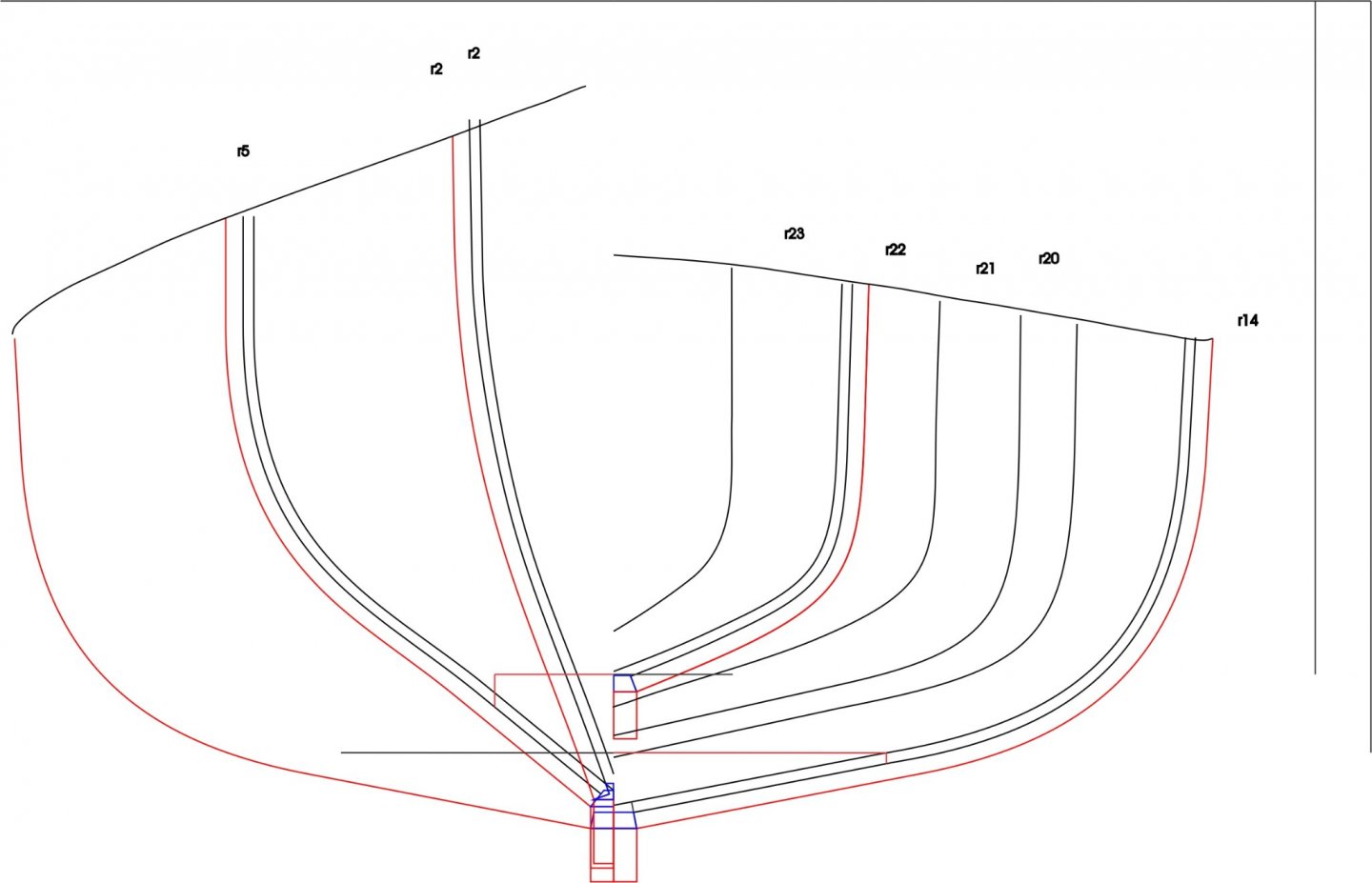
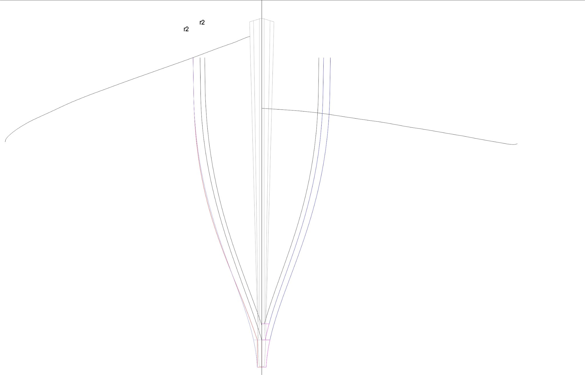
Initially I thought I was on this track, I think that I made the whole keel too small on the vertical size, also I drew the keel as a rectangular section. I am thinking that this was an error. The keel is basically rectangular but not the whole keel the forward portion is most likely shaped to conform to the lines of the hull to create a smooth transition from the Stem to the keel for at least a few stations and gradually transitioning to the more rectangular section.
I have redrawn station 2 to correspond to this notion.
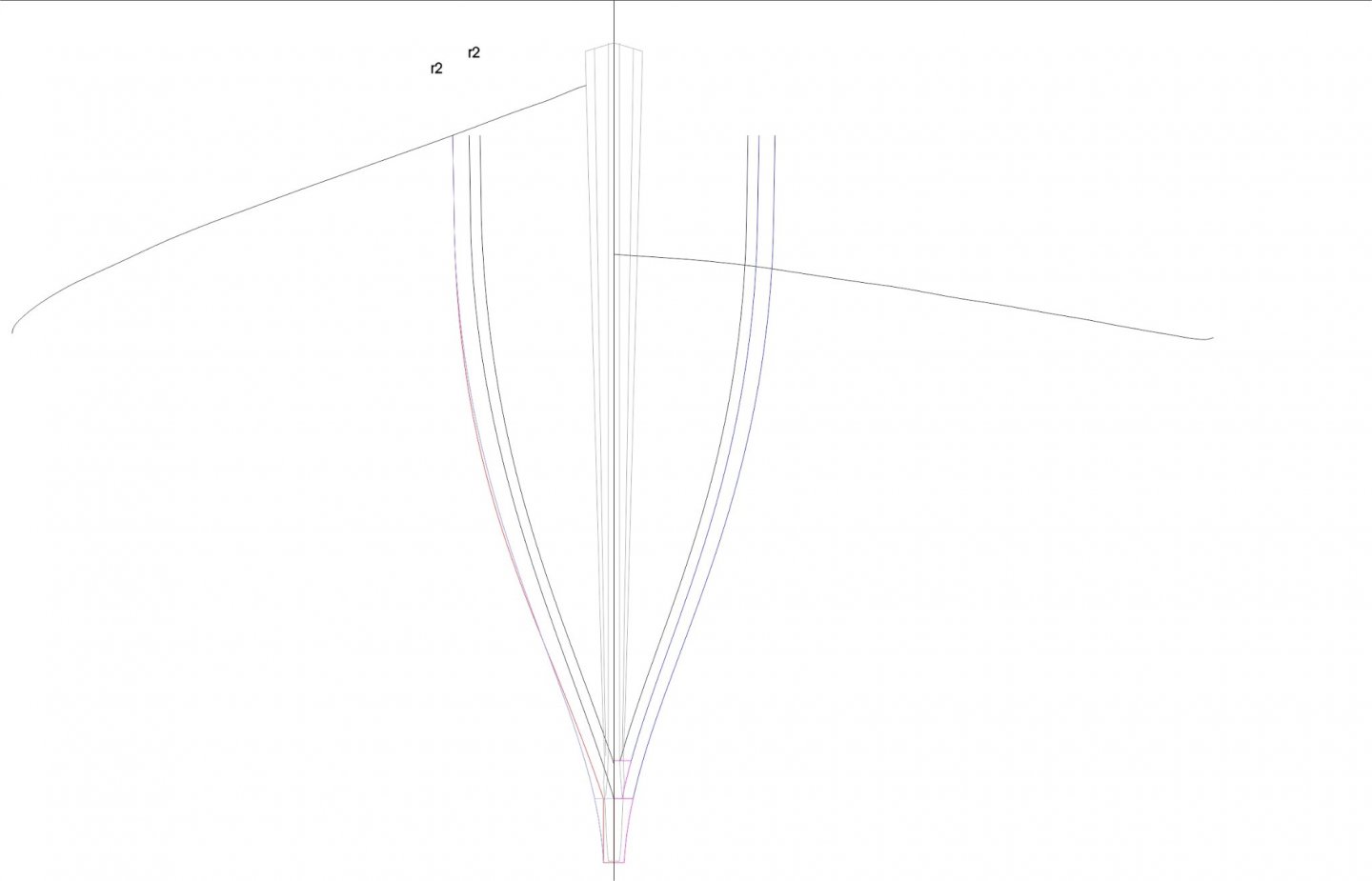
And in this close up of the keel area the right side of the drawing shows the rectangular keel as made in red with the newer profile mirrored on the right. I am guessing that the planking was thinned down to around 1/2 inch as it meets the stem at the keel. It would look quite chunky if it remained 3/4 which is what the thickness of the yellow Cedar is. The magenta line shows the taller keel section with a height of 4 3/4 by max width of 1 3/4.
Why am I getting this feeling that I need to start over,,,,,,,sigh!
Michael
-
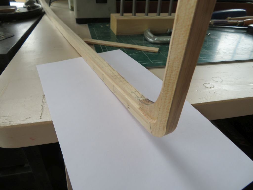
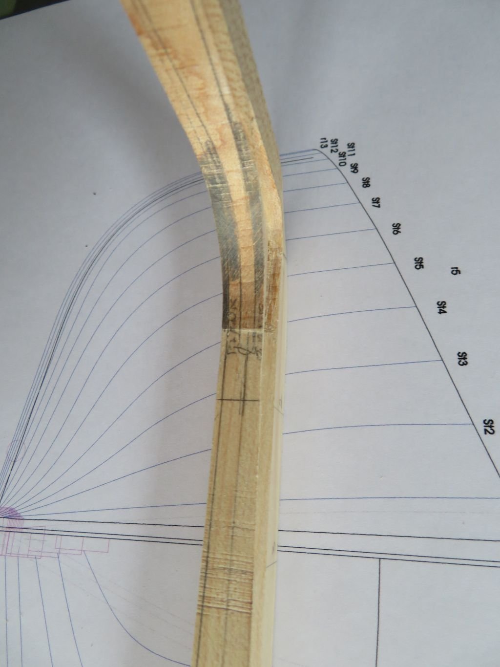
There is nothing like doing a bit O' wood butcherin' to begin to understand the way things work as opposed to how one thinks they are supposed to work.
Trying to really understand the interface between the keel and the Garboard strake. I twisted up a bit of 3/32nd yellow cedar and the plank certainly needed to be thinned a bit at the bow. This is just a basic test to see how the two parts mate and how to cut the rabbet which turned out to be completely different than what I had drawn. The garboard is just sitting there gravity holding in place.
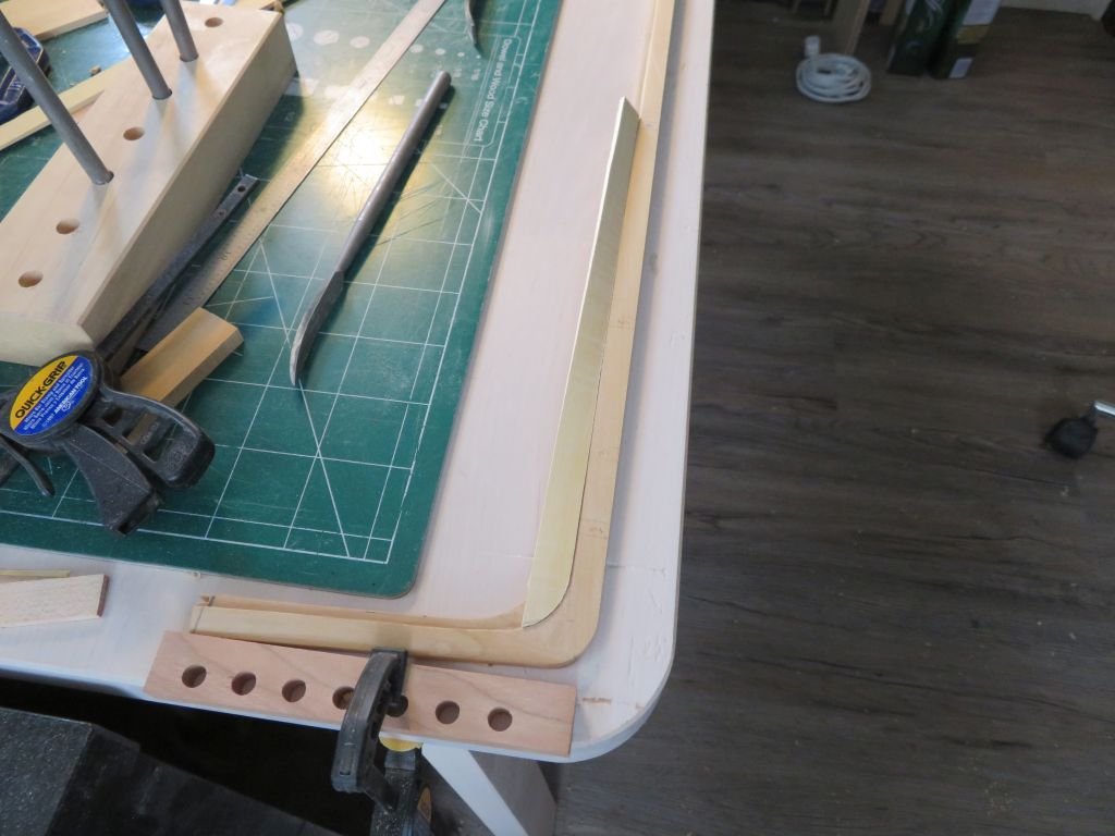
Now I understand it a little better.
Michael
- GrandpaPhil, mtaylor, dvm27 and 9 others
-
12
-
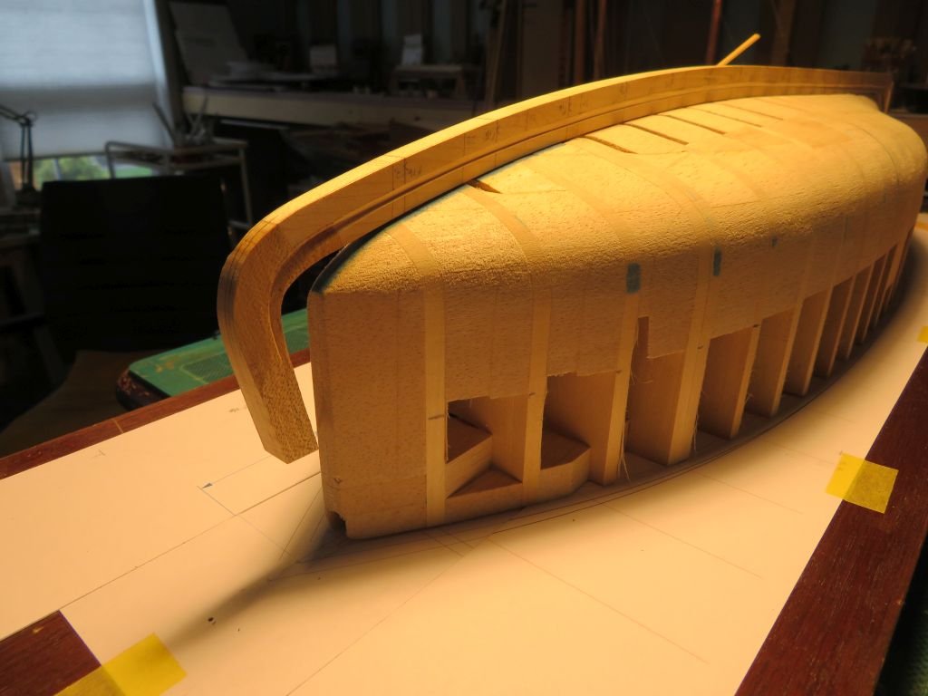
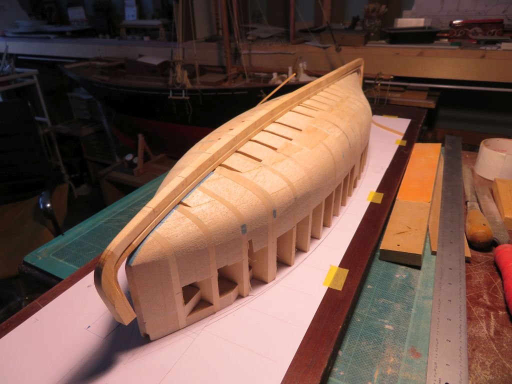
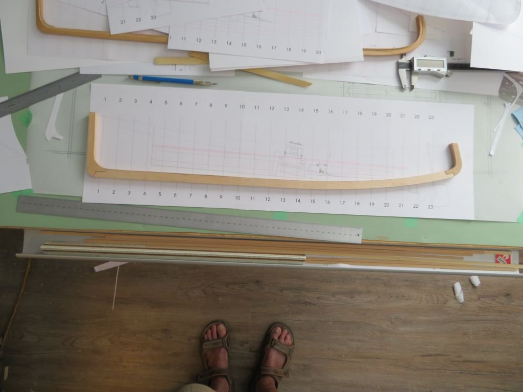
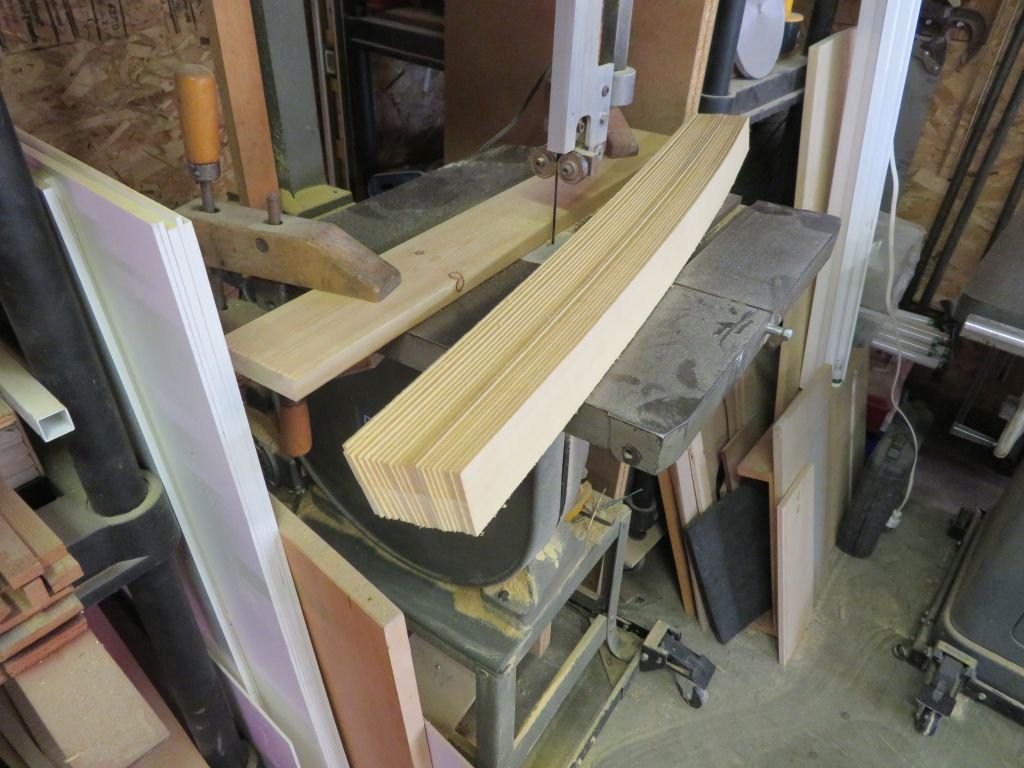
Did not do too much today just a bit of refining of the keel drawing and gluing the top part of the keel to the lower I used a darkened PVA glue in order to see the glue joint as I shape it.
Also rough cut 22 sheets of Yellow Cedar for the planking. There are 11 planks each side. The planks were 3/4 inch thick which makes them 3/32 thick for the model. I used the jointer to plane the edge each time next to the fence.
Michael
- GrandpaPhil, FriedClams, mtaylor and 11 others
-
14
-
Hello Valeriy, like some others I am just catching up. You have a fine touch with the metalwork. I to like your small details such as the chain and shackles. The capstans are small works of art in themselves. I like the method that you used to create the vents as well.
Michael
- mtaylor, Keith Black, FriedClams and 1 other
-
4
-
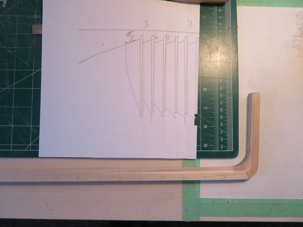
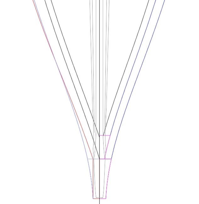
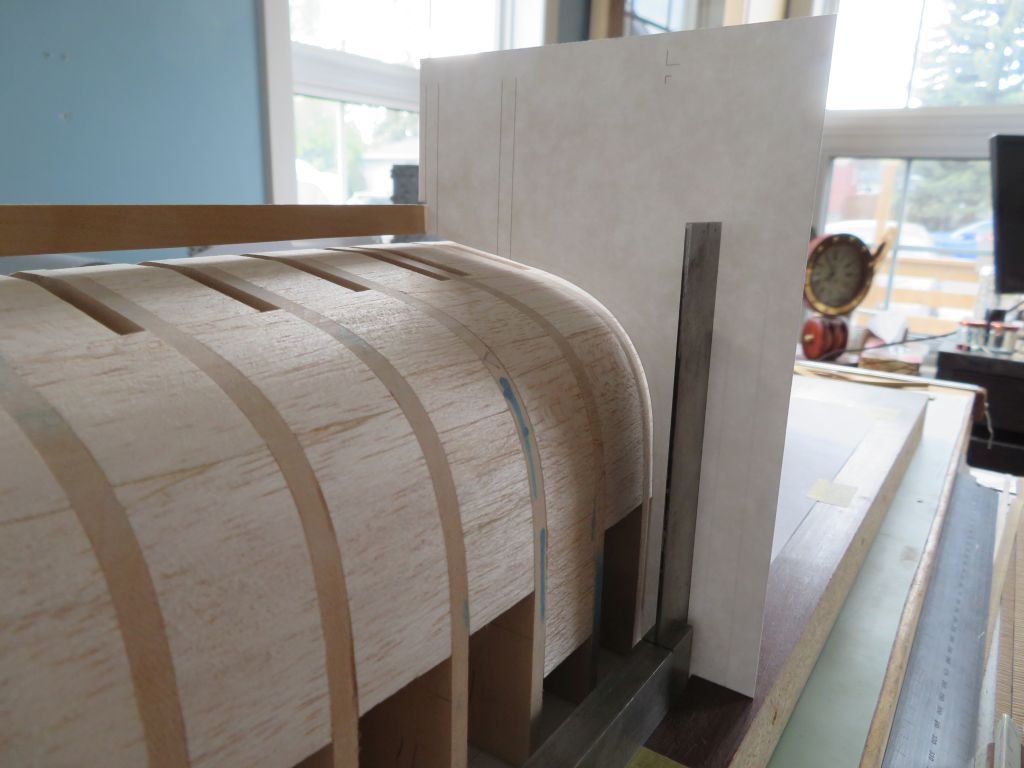
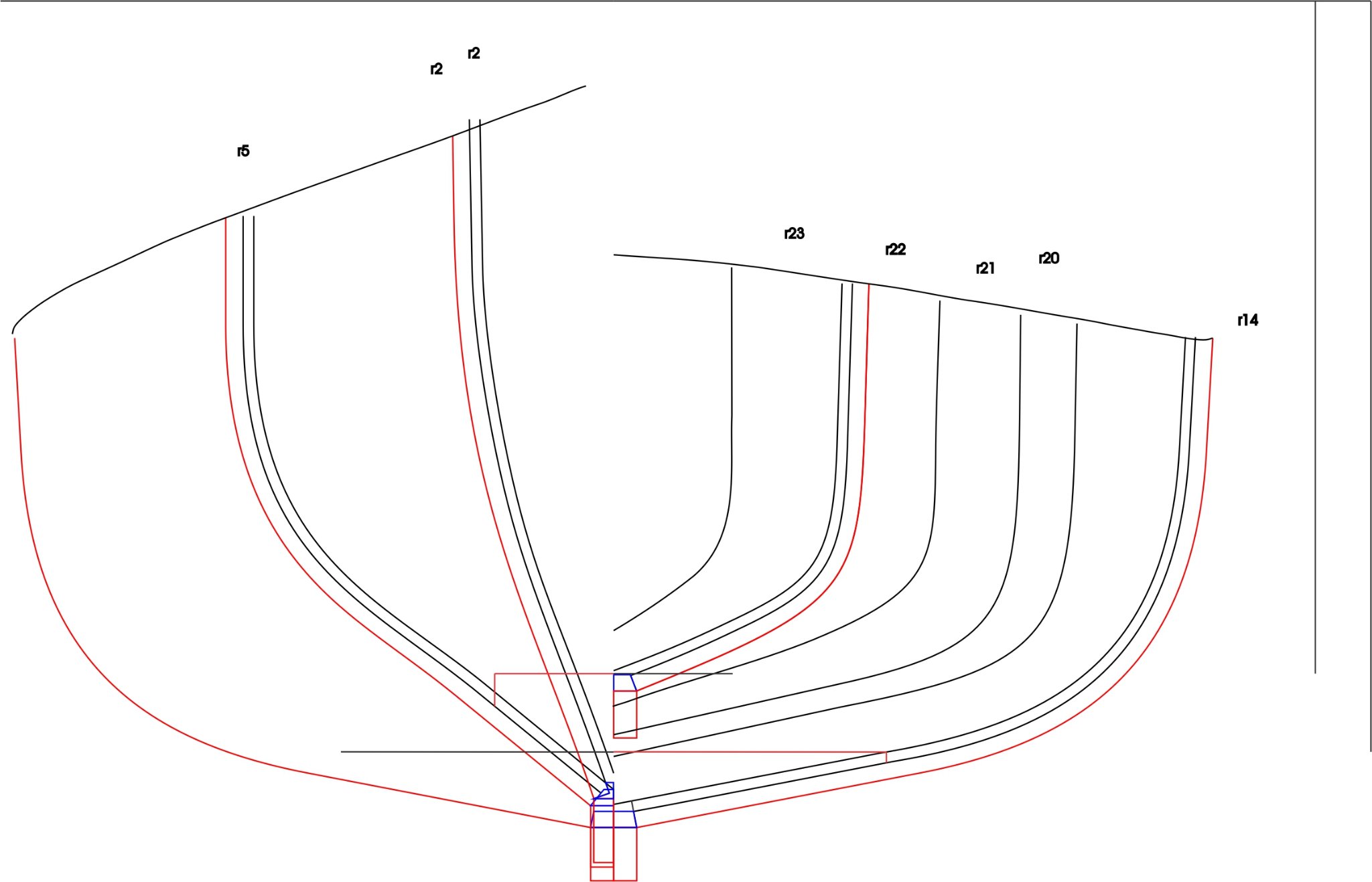
Today was another one of those aha moments when I realized that the top plate of the keel was not drawn correctly, You Know this model shipbuilding from scratch is not for the feint of heart is it! I picked up some printable card stock to cut yet more test templates to see how the frames and keel and planking all intersect at the keel.
This was the Aha moment.
The red line is the outside of the planking , the two black lines represent the frames and the blue represent the top layer of the keel. These test templates match up with station lines 2 ,5,14, and 22. Also the two positions of the floor of the open cockpit are shown as the horizontal lines and how the interface with the frames at #5 and #14 which is where the floor steps up around the engine. I am really hoping that this all comes together as a model that looks like the real boat!
#5
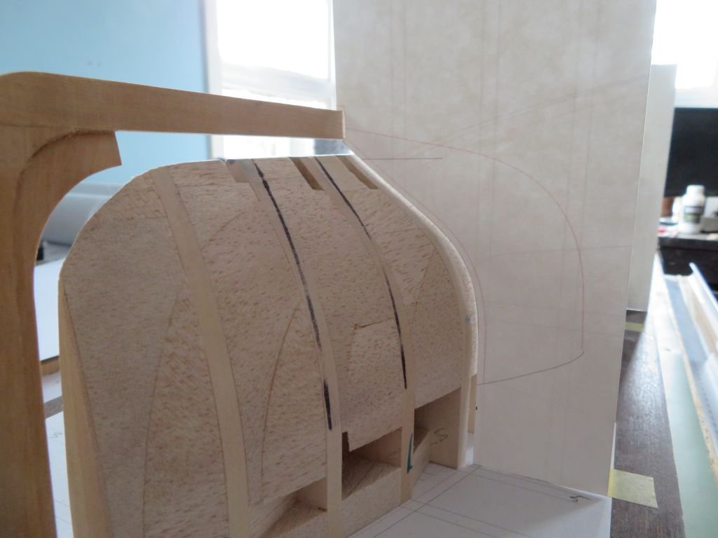
#14
# 22
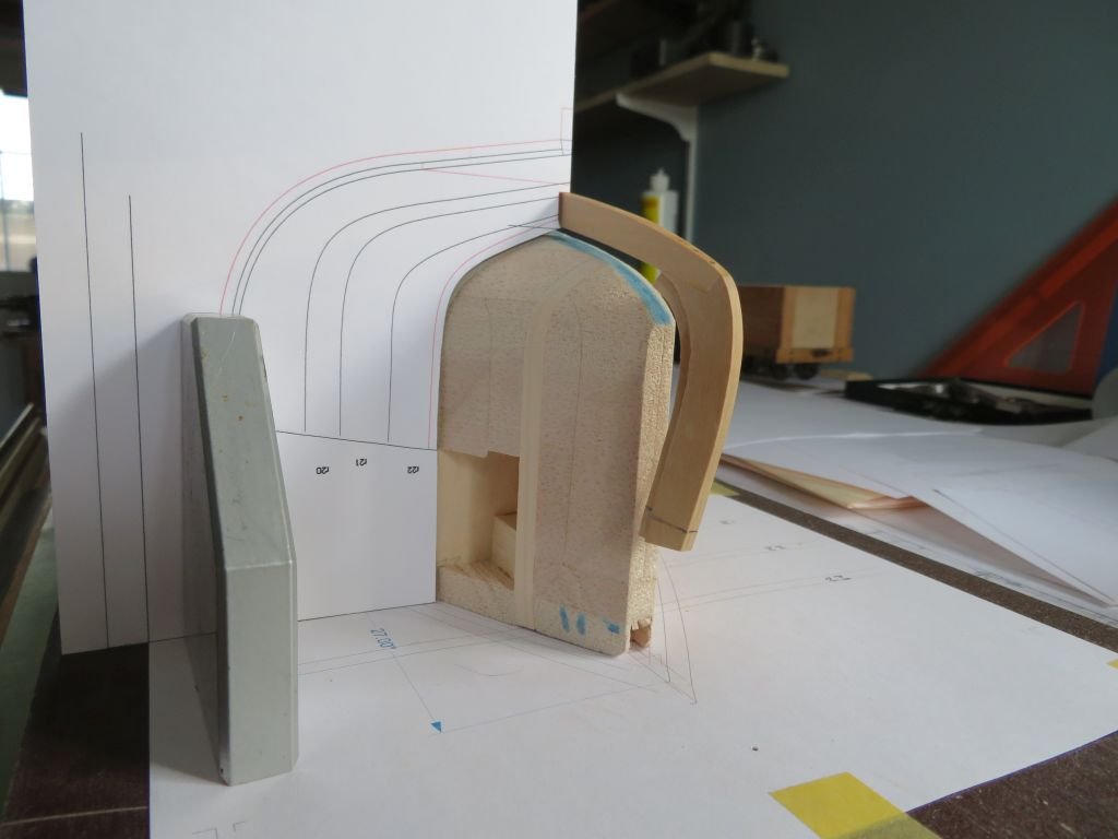
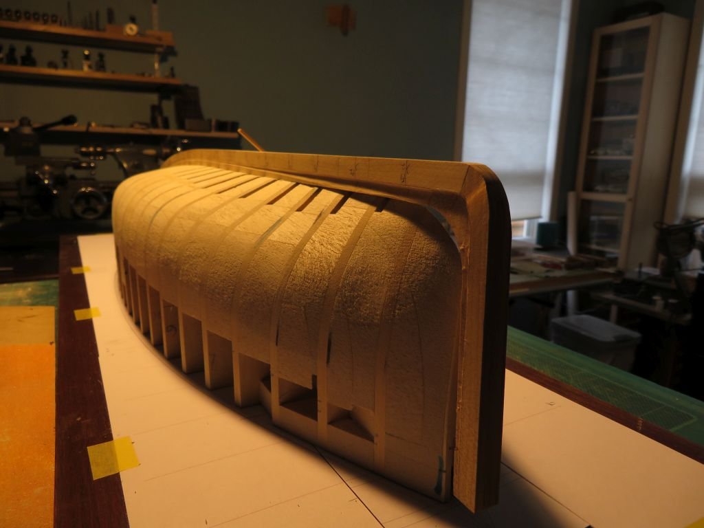
From the side the space is clear that I now need to add the top part of the keel which is much narrower that I had originally envisioned.
That enough for today.
Michael
-
Models like this from you Druxey is why we turn to you for advice and inspiration. simply outstanding workmanship raised to the level of fine art!
Michael
- bruce d, thibaultron, drjeckl and 7 others
-
10
-
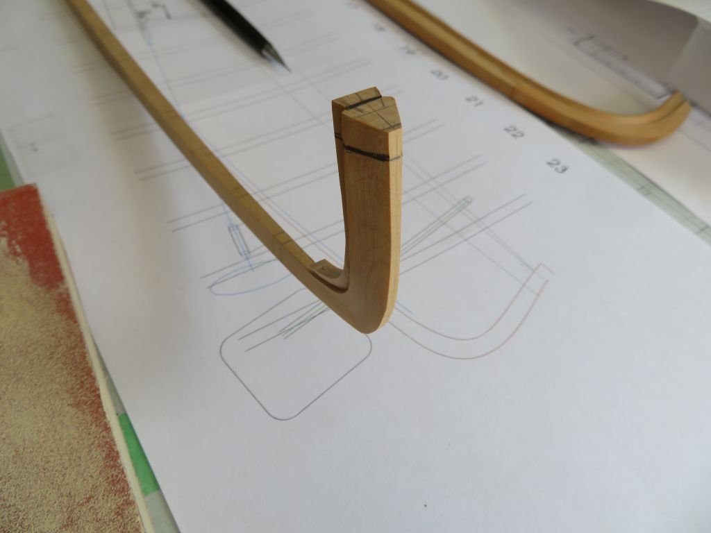
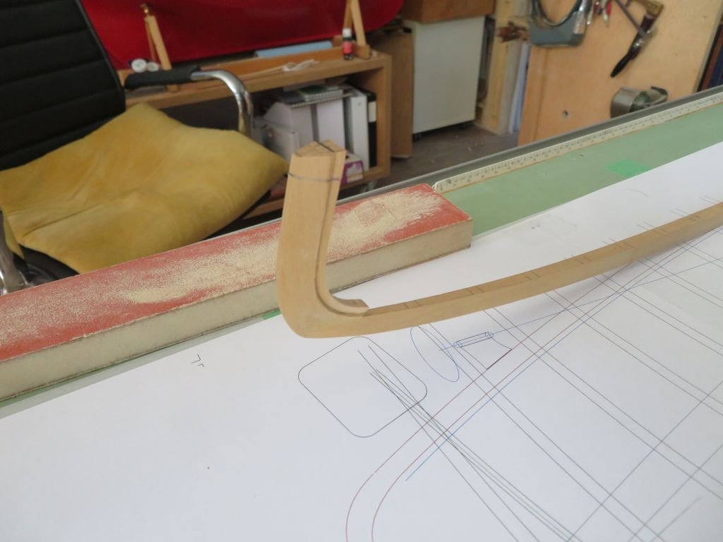
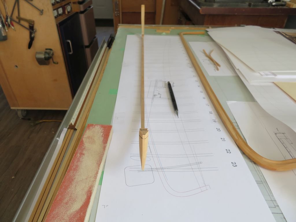
I am so glad that my little model shop is air conditioned, it was 31C here today and anything above 20-22C I find uncomfortable.
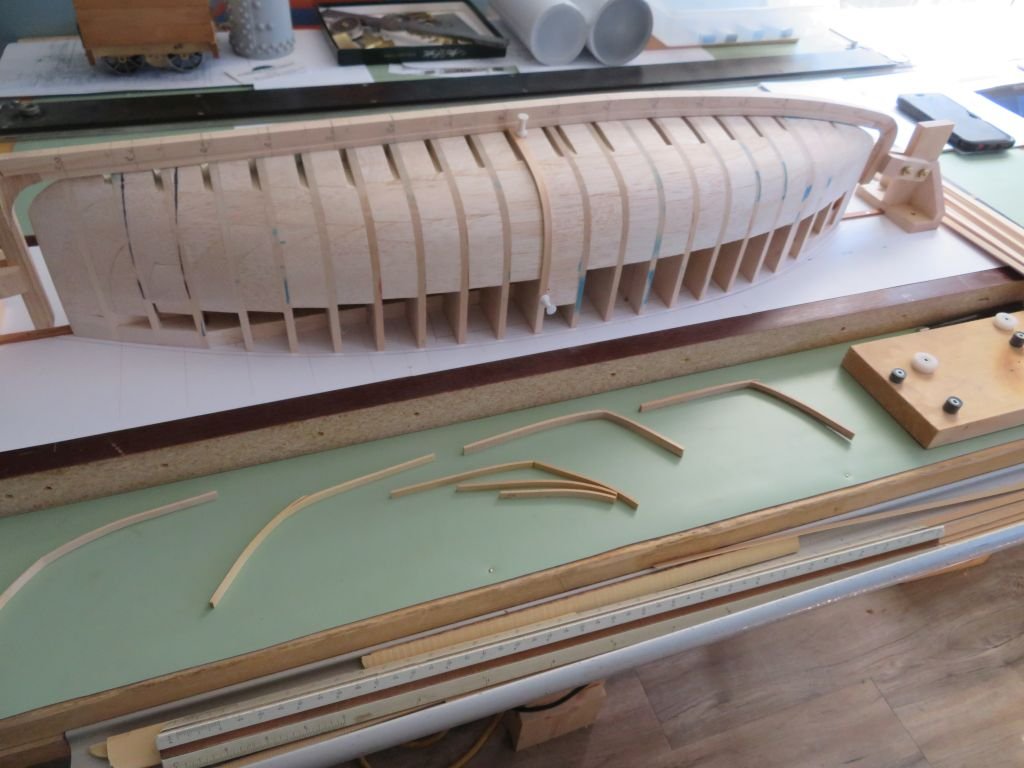
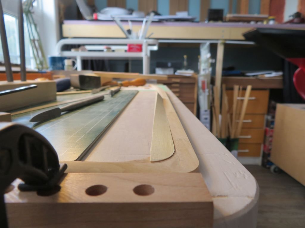
Finished rough shaping the stem today so now I can concentrate on the frames and floors.
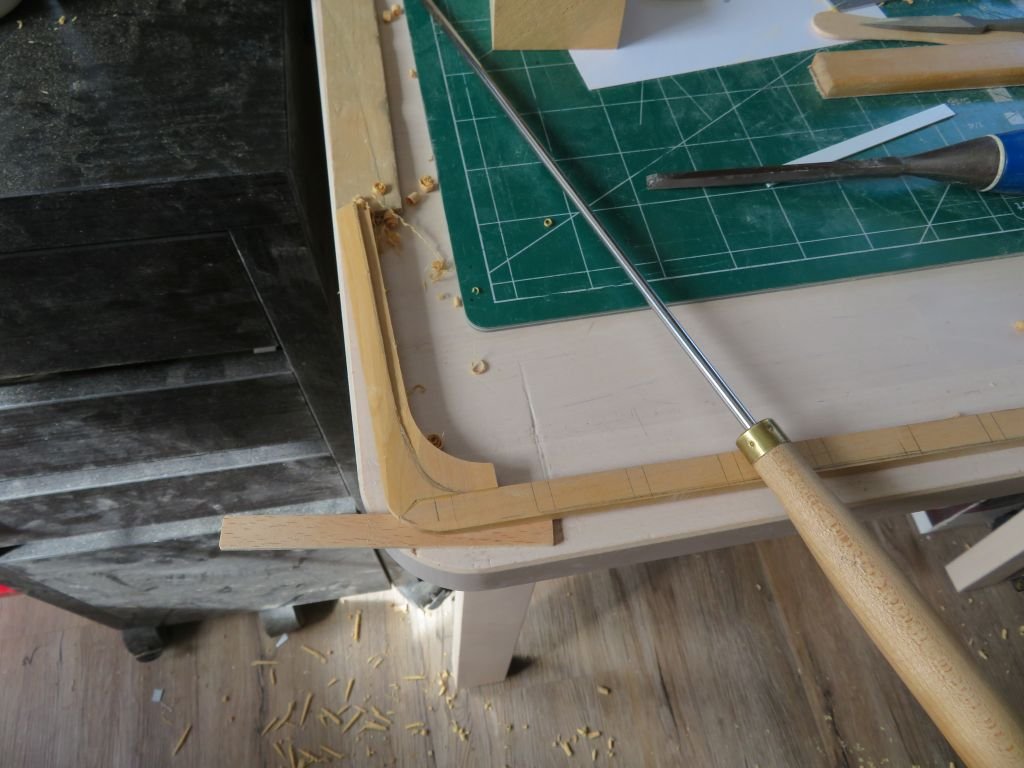
I am quite happy with it
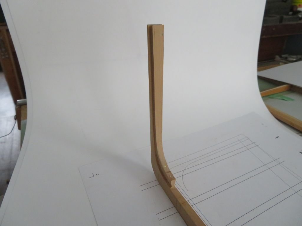
Her is a comparison between the first keel and stern and the new one, Although I do like the overall shape of the first Perhaps I can build a freelance model on it at some later date or lifetime.😉
Michael
- GrandpaPhil, G.L., vaddoc and 9 others
-
12
-
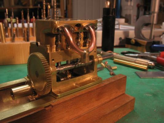
Eberhard, Yes the engine is mostly built there is quite a lot about it earlier. here is a teaser image.
Michael
-
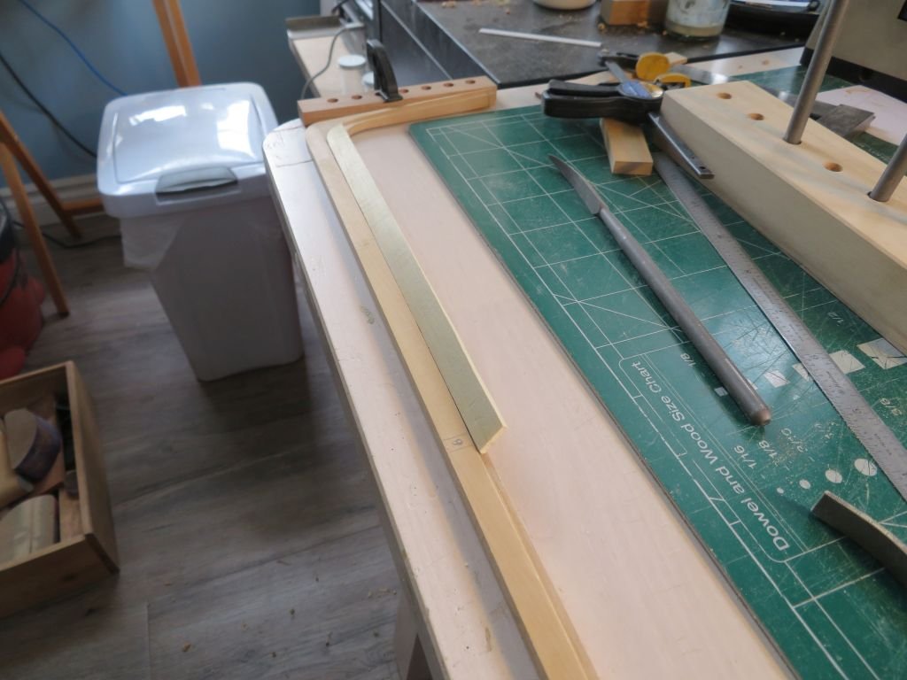
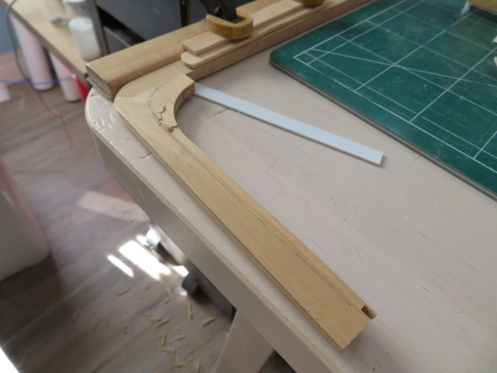
Worked on a bit of carving the stern today. first I set up to add the (bronze drift bolts) brass .046" dowels these were angled differently from each other, similar to a dovetail
Then using riflers to rough shape, along with some careful #11 exacto work the stern is done far enough for the moment.
Tomorrow the stem.
And as an aside I was able to book my second Covid Vaccine for Friday the 5th June, this afternoon, when I logged onto the AHS site there were only 21,000 ahead of me with a wait time of 26 minutes till it was my turn to book.
Michael


28 foot American cutter by druxey - FINISHED - 1:48 scale
in - Build logs for subjects built 1851 - 1900
Posted
There is something very appealing about these smaller models, and it is a testament to your skill and ability to be able to create such a gem.
Michael