


michael mott
-
Posts
5,195 -
Joined
-
Last visited
Content Type
Profiles
Forums
Gallery
Events
Posts posted by michael mott
-
-
Tom I spent a lot of time contemplating the purchase of the hex plate, it certainly was not cheap but has 20 different hex sizes and for me it has enable me to create both nuts and bolts of many scale sizes out of a few diameters of rod. The scale threads are a hole different matter and are a limiting issue.
Michael- Keith Black, druxey, mtaylor and 9 others
-
 12
12
-
Not a lot more progress to report on this project which has been challenging I feel that it will not be worked on much over the next few months as a couple of commitments that need to be completed by the new year take precedence. A few more pictures of the work done over the last year.
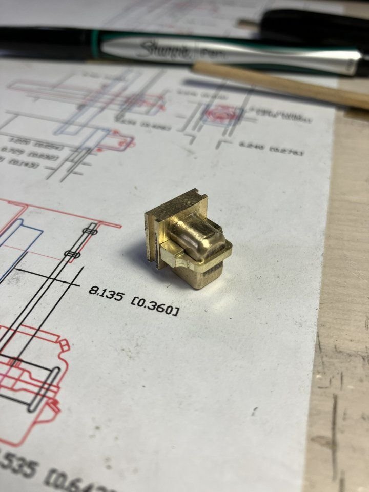
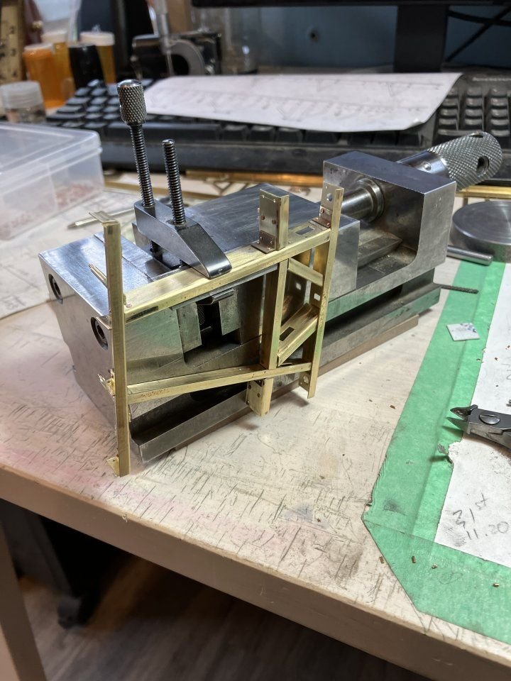
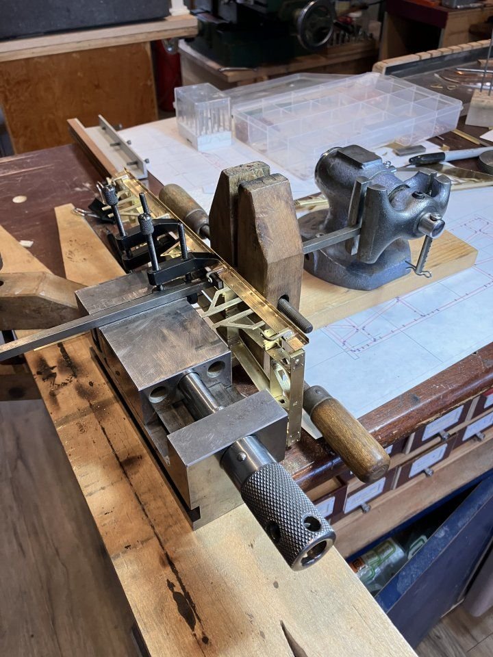
After the springs were completed the next work involved preparing the wheel bearings These are basically a solid block of brass with some additions added to dress it up. the first picture shows the basic block with the initial shaping and fitting to ensure a good slide fit into the "W" irons.
The prototype is manufactured out of two castings bolted together and to replicate this I slotted a piece of brass into the block with the thicker area that would hold the bolts.
The insert and a top block were soldered together using some high temperature soft solder, my third hand has been very handy during this entire project so far.
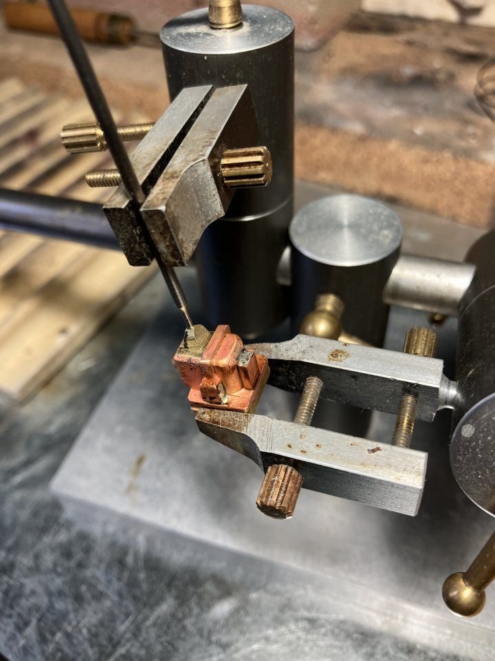
Once the soldering was done and cleaned up holes were drilled for the various bolts and oil caps, these were formed from a few different diameters of brass rod annealed and pulled through my Hex draw plate. the bolts are glued in place with AC glue.
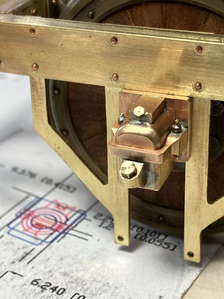
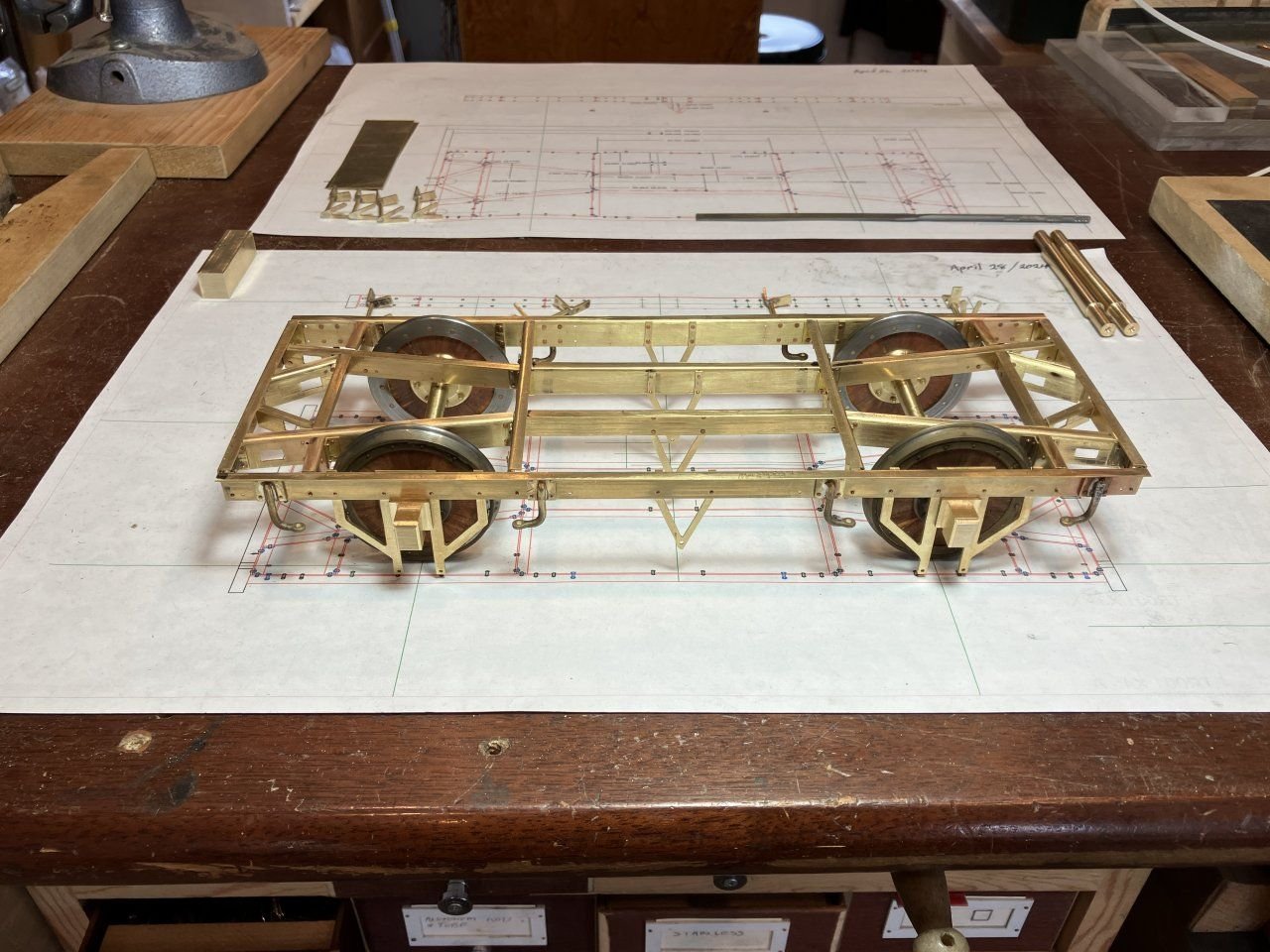
Now with the springs and bearings the under-frame is beginning to look like the contemporary frames of the period.
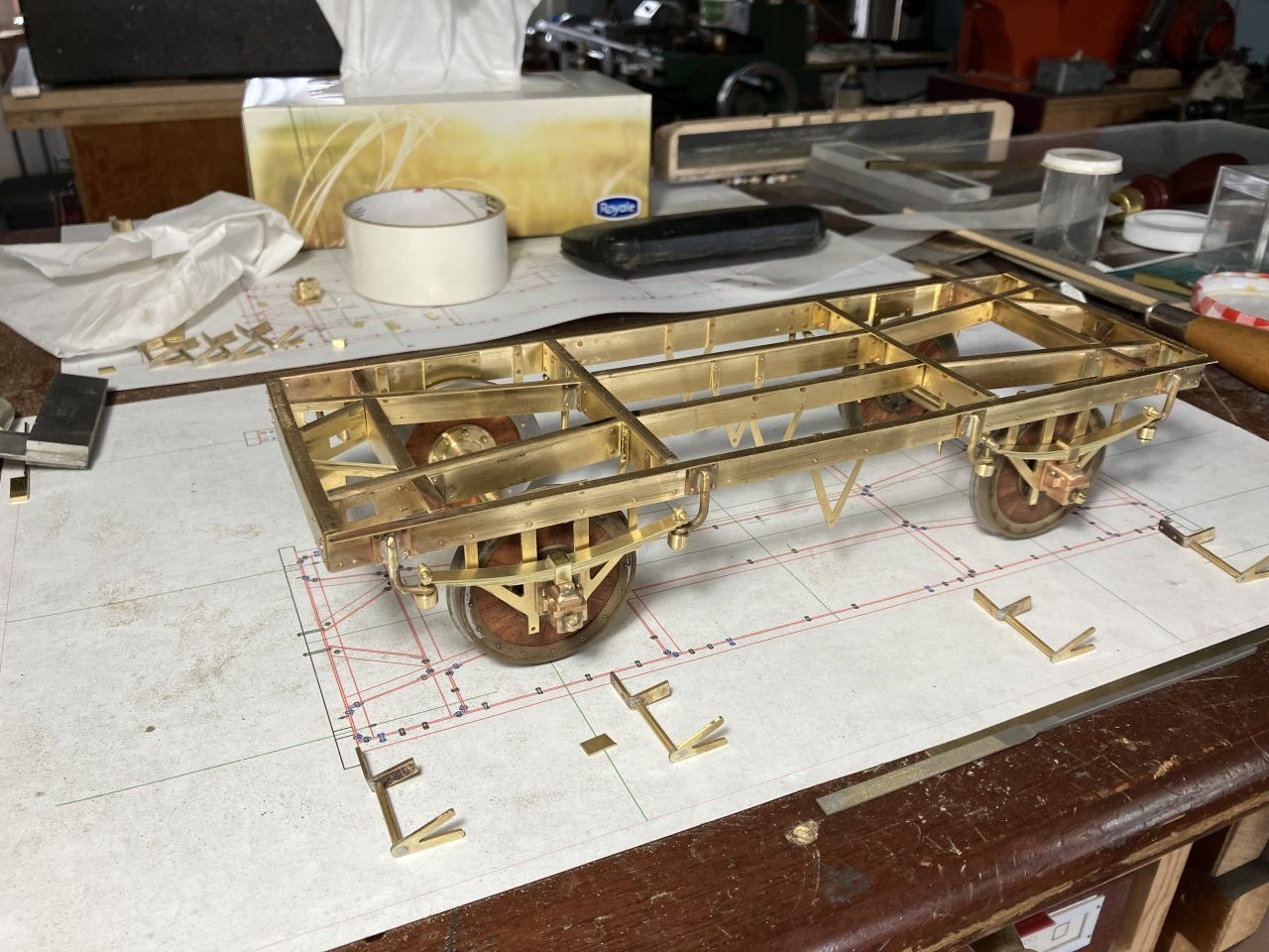
The frame has a decent amount of springiness.
to be continued
Michael
-
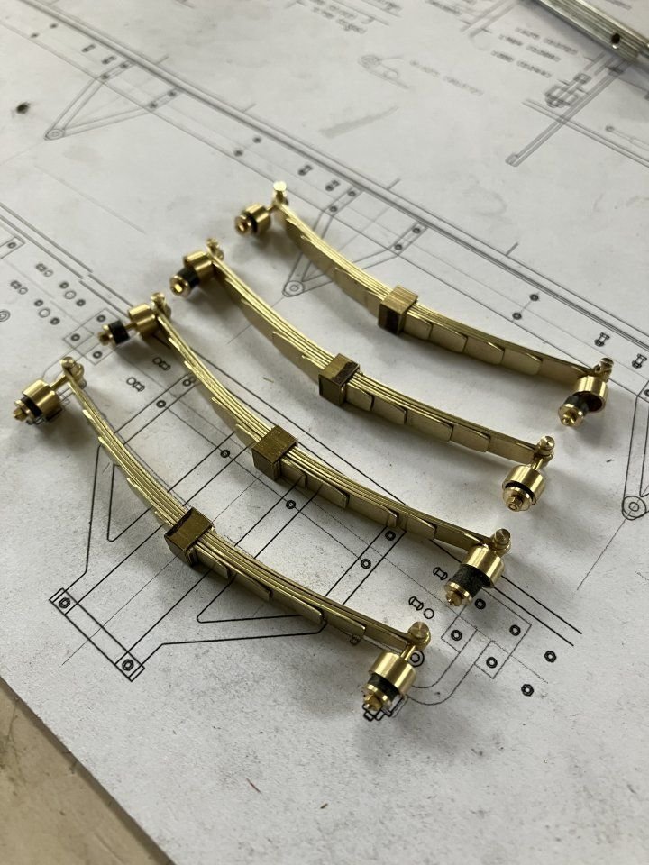
A few more pictures of the progress of the van. The next area to tackle was the springs, I thought about this for a while, and decided that because this van would not get a lot of use in a real sense that I prefer building to running the models, that Hard brass sheet would be sufficient for the springs. The top leaf is the most complicate I had to make a small jig to ensure that the loops at the ends were consistent, but rather that a fixed jig I opted for an adjustable one.
first yo bend the strip to length and then using the jewelers saw to cut the excess off
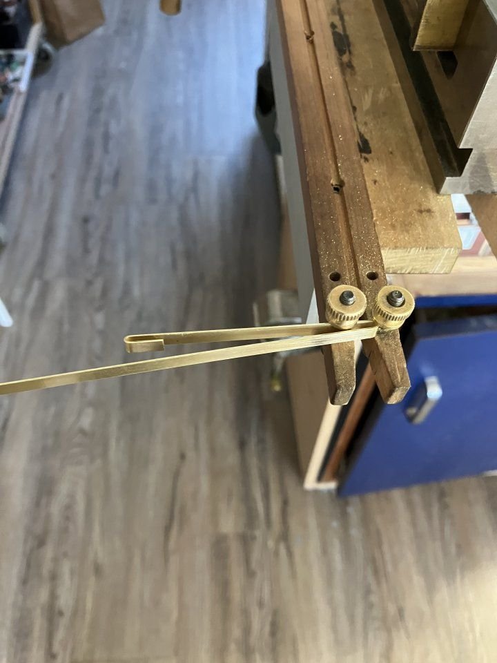
then to close the loops with some parallel jaw pliers
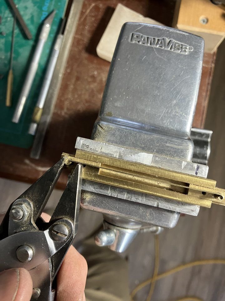
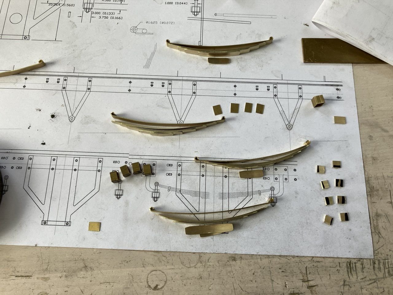
The rest of the leafs were straight forward , to get the correct curve was a trial and error wood jig reducing the diameter of the curve until the correct bend was achieved then it was just a matter of cutting to length and drilling the hole in the centre after bending. The reason for bending the curveafter was to avoid the kink in the middle that was caused by there being less material and so it bend more easily at that point.
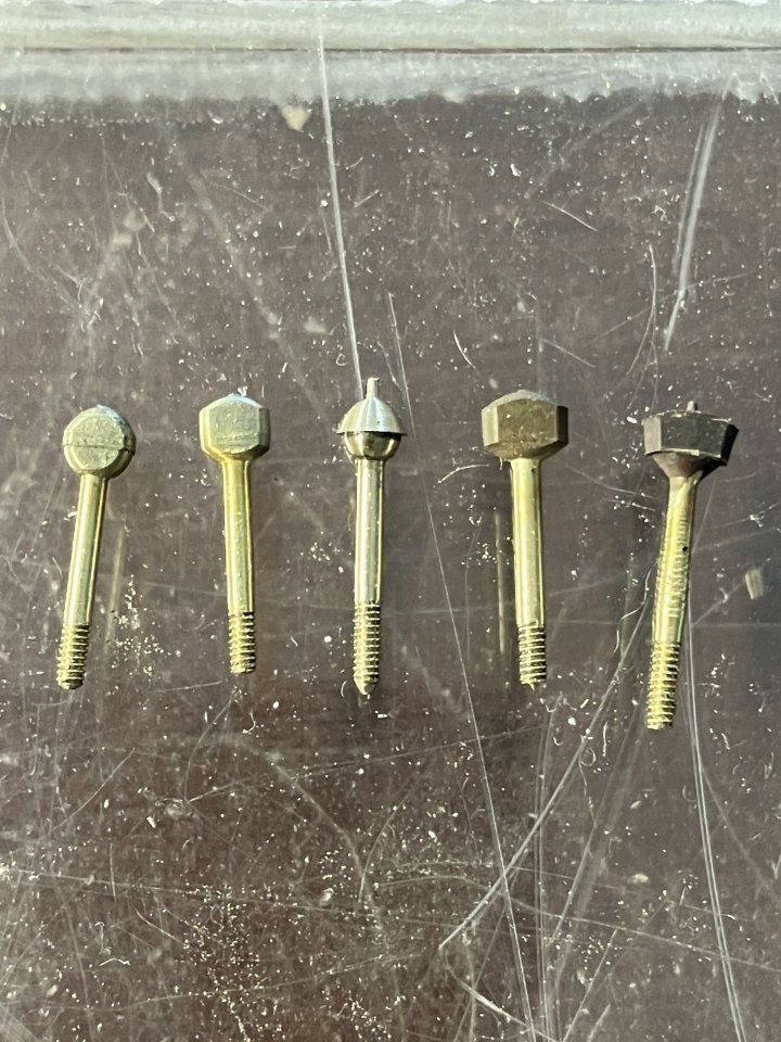
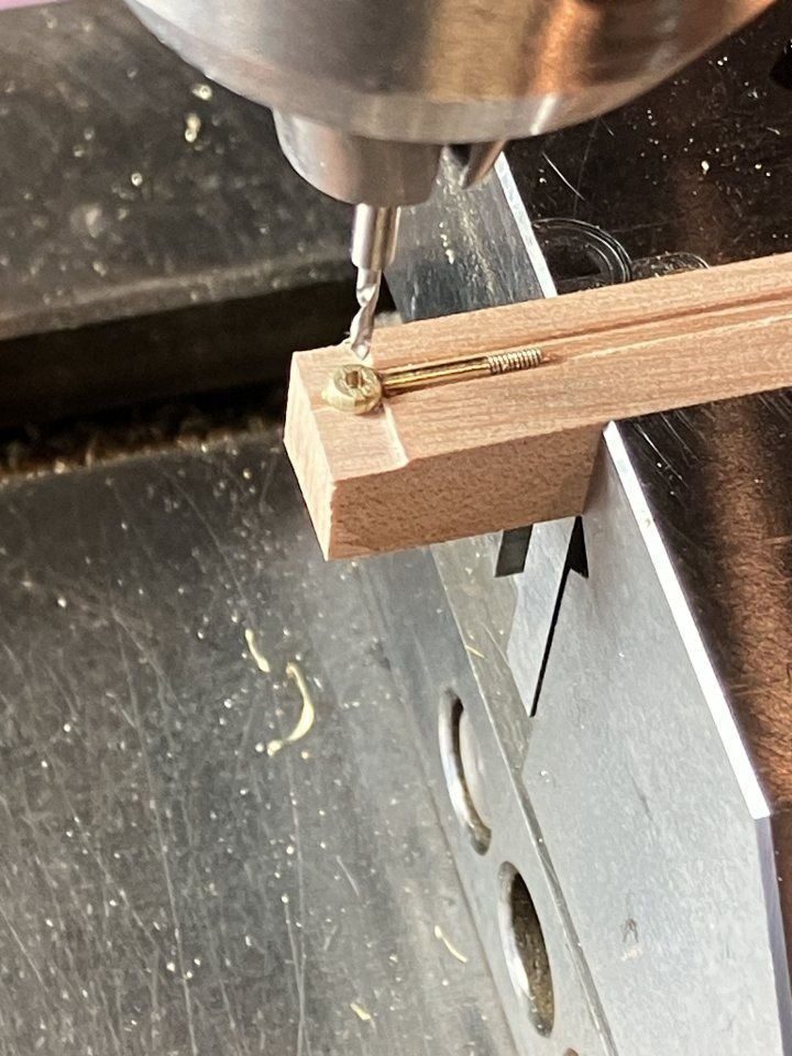
Next were the spring hanger bolts, I used the similar method to the one I used to make the shackles for the Cutter only I also needed a thread and only one forged end.
Beginning with 1/8th hard brass rod I used a single form tool in one pass to reduce the diameter and form one end of the bulb that would get flattened, and in order to thread the end 00x90.
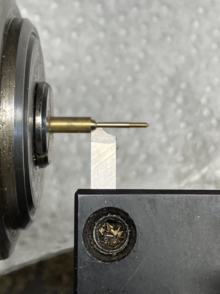
Then after indexing the tool forward ised it to form the other end and part off in one motion, a little crude but it worked.
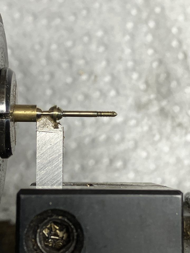
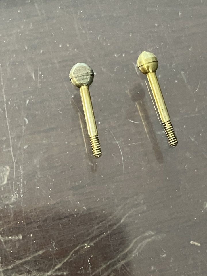
A picture showing the evolution of the method arrived at above.
a simple wooden holder to drill the holes before they were added to the top leaf.
The rest of the hanger bolts was a simple inverted cup to hold the 3/16 section of "O" ring with an .047 inch hole drilled through it to represent the rubber dampening part a flat washer and nut completed the assembly.
a bit of square tube was used to form the central keeper and a pin through to keep it all aligned.
to be continued
Michael
-
13 hours ago, TBlack said:
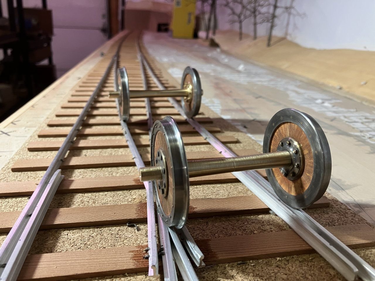
Nice work on those wheels/axles. Dimensions spot on. But I’m worried about those railroad ties not being treated.
Tom
I am still working out how to obtain miniature creosote barrels in order to treat them😉
18 hours ago, druxey said:Terrific, Michael! Your metalwork is equal to that of the late, great Gerald Wingrove.
Druxey I am honored to be thought of in the same vein as Gerald Wingrove , I have been an avid admirer of his incredible work for over 50 years, thank you.
Michael
- thibaultron, Jack12477, Egilman and 7 others
-
10
-
Continuing on then here is a bit more of the progress much of this work has been done over the last year.
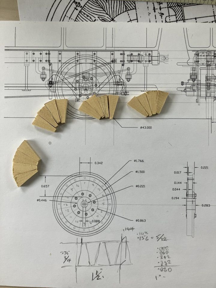
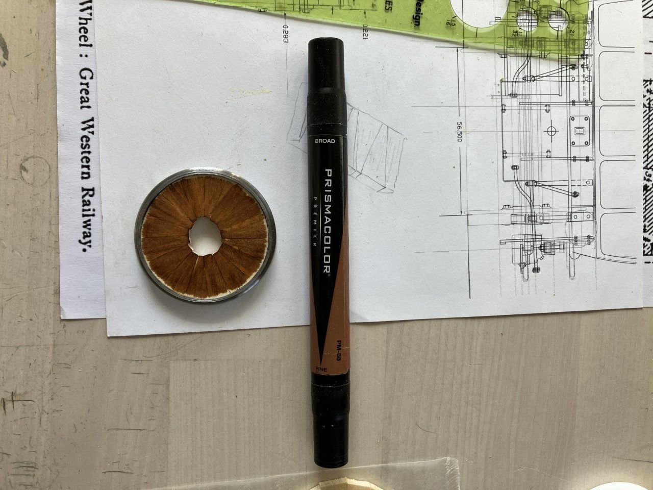
The wheels are a combination of wood and steel the wheels used on passenger vans etc were Maunsell wheels the idea that by insulating the steel tyres from the hubs with hardwood would eliminate the noise generated by steel on steel over the joints etc.
after choosing some yellow ceder for texture and ease of working I cut four sets of 16 oversize in length wedges and began gluing them together in pairs.
after a while the set of pairs became sets of four,
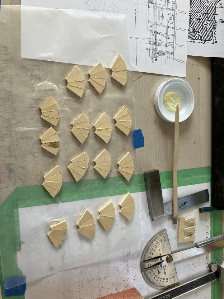
and so on until I had two halves that were easy to get flat to match and then glued those together, these were then trimmed on the outsdide diameted with a jewelers saw and slowly sanded with sanding sticks until they slipped snugly into the tyres, then colored with the pentel pen.
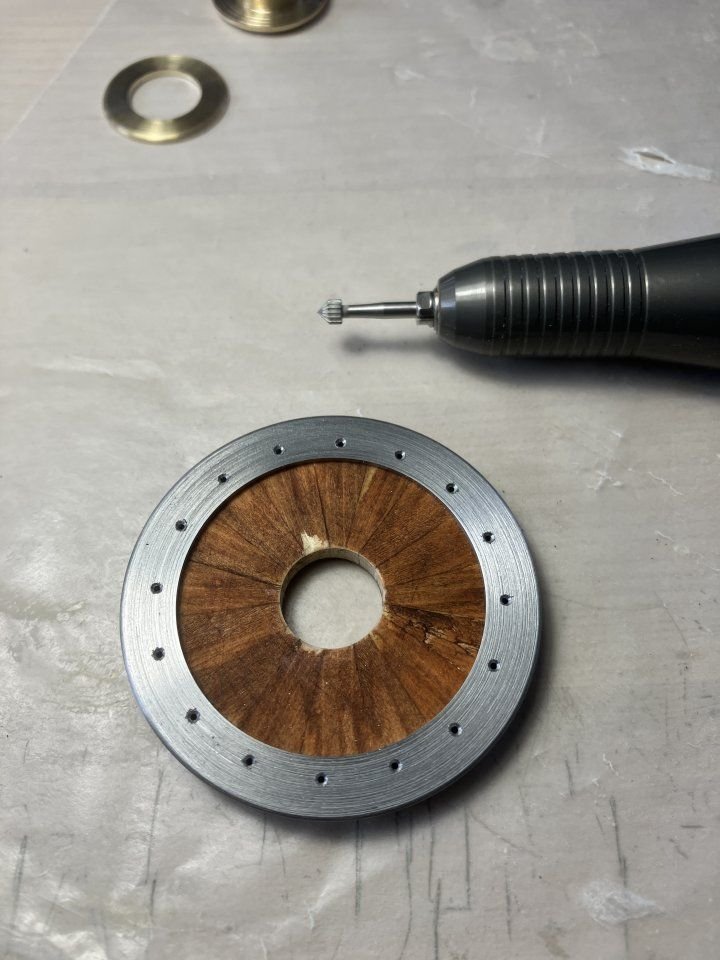
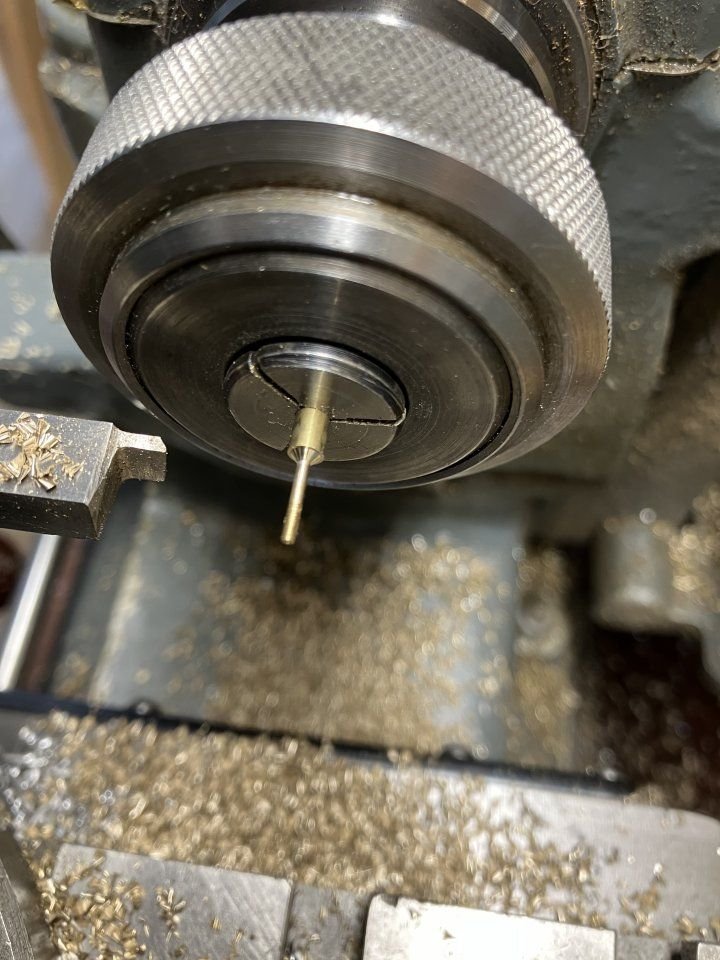
After the wood had been glued to the tyre I was able to bore the centre hole for the hubs, the wheel was then set up on the rotary table to bore the holes through the steel ring on the front face through the wood and the tyre for the 1/32 copper rivets. ( eventually had to make them from brass because I did not have enough of the right length so they were turned and annealed ) the backside was countersunk with the small hand held tool.
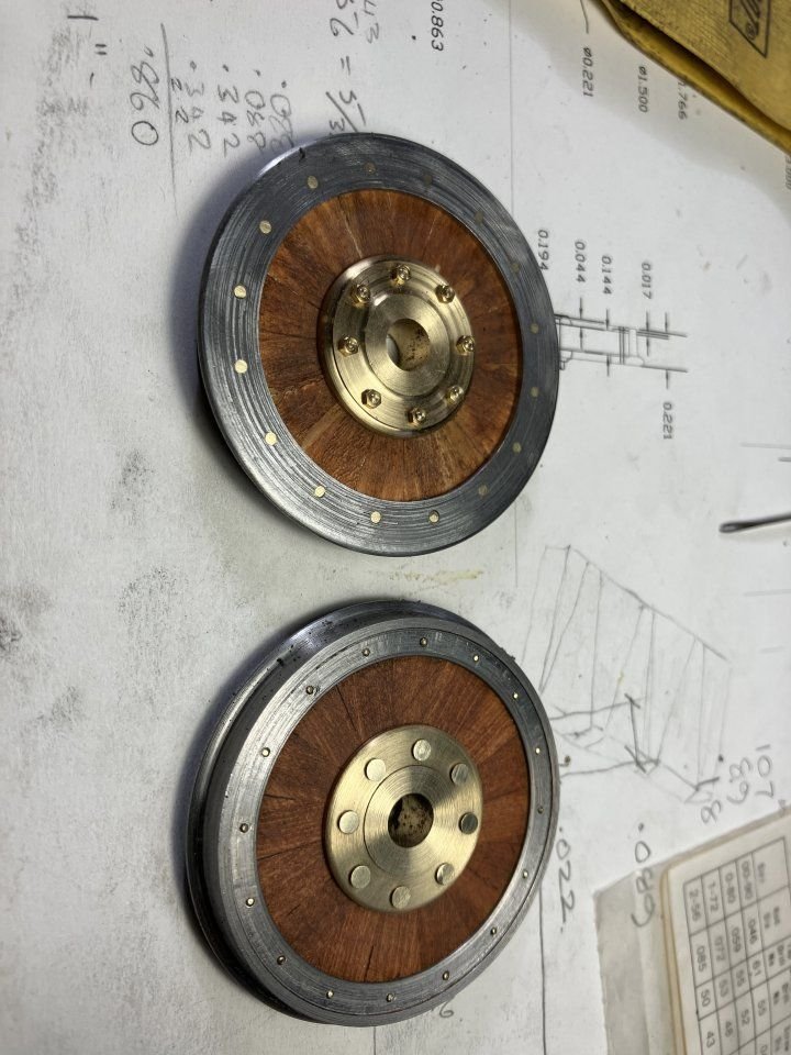
the first wheel with some copper rivets from the back and then flipped over to show the front side with the retaining ring
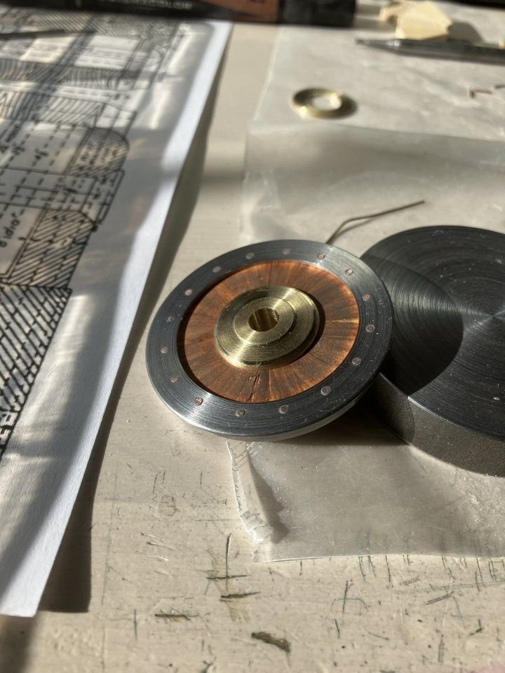
Using the same method a the sets of turned brass rivets I machined up some flat-head brass 00x90 bolts to assemble the hubs.
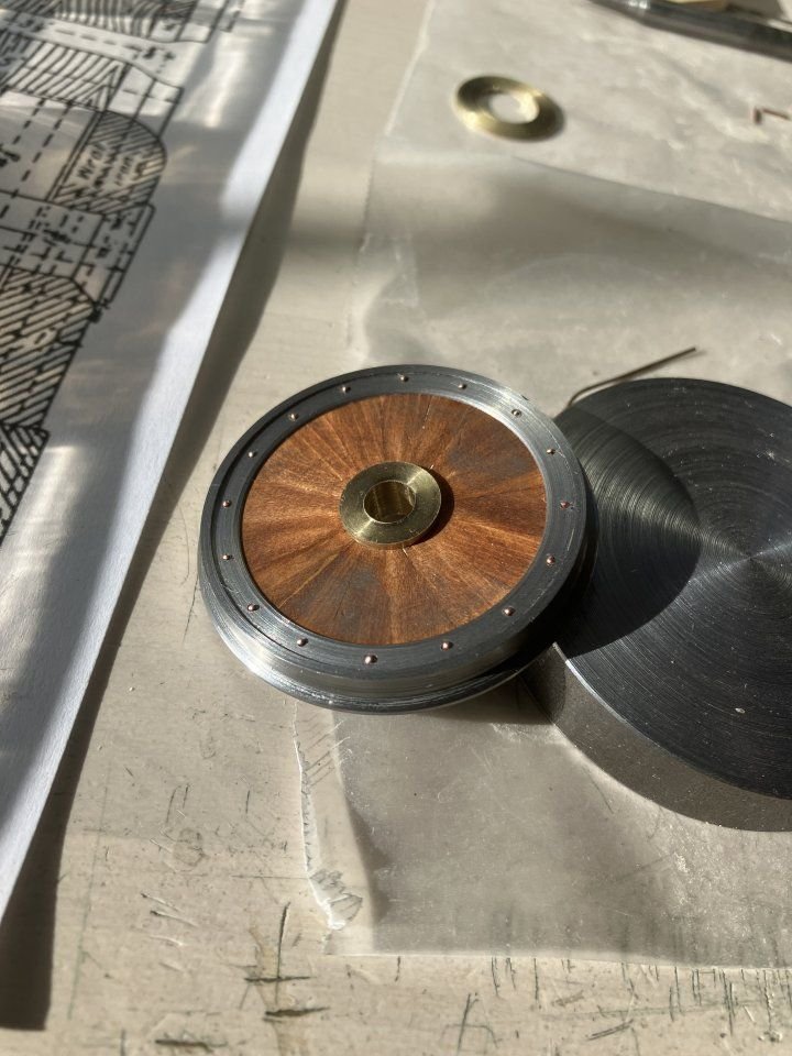
then bolted them together.
and finally set loosely on the axles.
to be continued.
Michael
I chose brass because I had the right diameter to do the work.
-
Lovely work Kieth.
Michael
- TBlack, Glen McGuire, mtaylor and 3 others
-
6
-
Thank you all for your kindness and welcomes. Here are a few more pictures of the restart as Druxey so aptly called it.
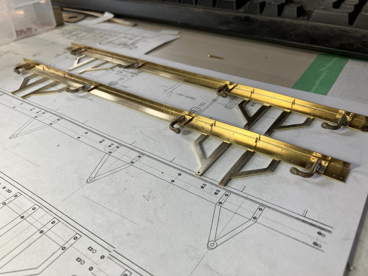
After bending up the angles I then used a vice and a little work with a chunk of mild steel flat bar and suitable hammer to tighten up the corner. Next a set up on the mill to cut each leg of the Angle to the scale 3 inch x 9 inch accurately this was a slow process and a couple of hiccups before all the needed section was produced.
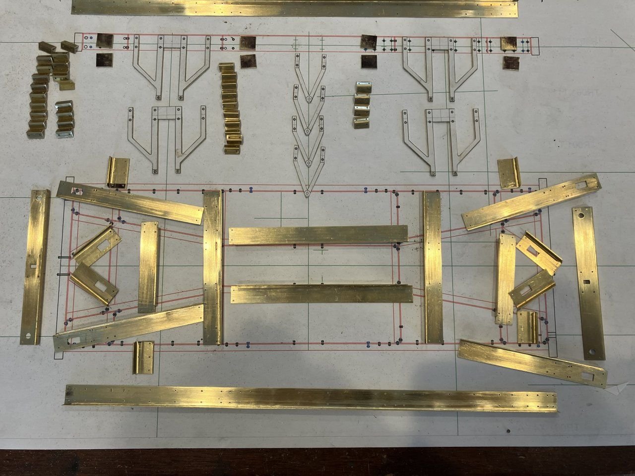
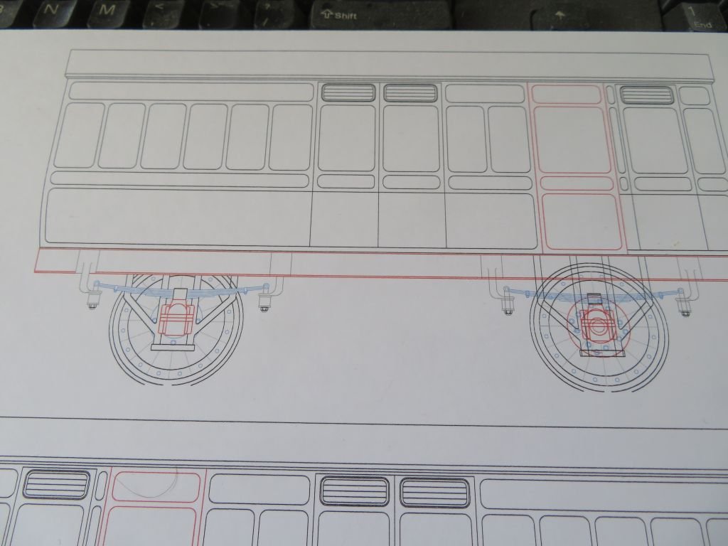
The individual parts were marked out and cut to length with the inevitable mistakes because of the right and left handing of angles and holes. I now have a number of extra parts for some other purpose down the road so to speak. A few test samples were made of the riveting of corners a couple of which were very challenging but I wasn't giving up. ( More trinkets in the spares bin.) One of the reasons for some of the changes was my changing the layout of the frame as there is no extant drawing of this particular under-fame and during the late 1800's the Great Western Railway was undergoing all sorts of developments with the design of their rolling stock and Locomotives, as were all the other companies.
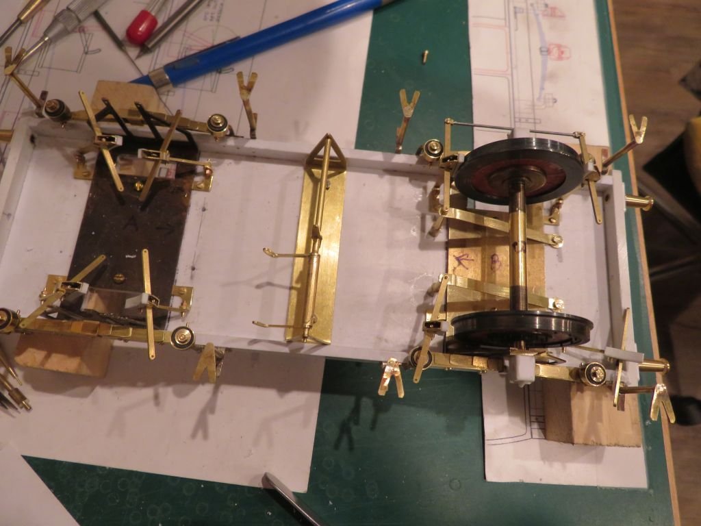
Once I was happy with my conjectural configuration based on the best practices and closest other frames of the same era I began riveting the frame together with 1/32 copper rivets.(very challenging indeed)
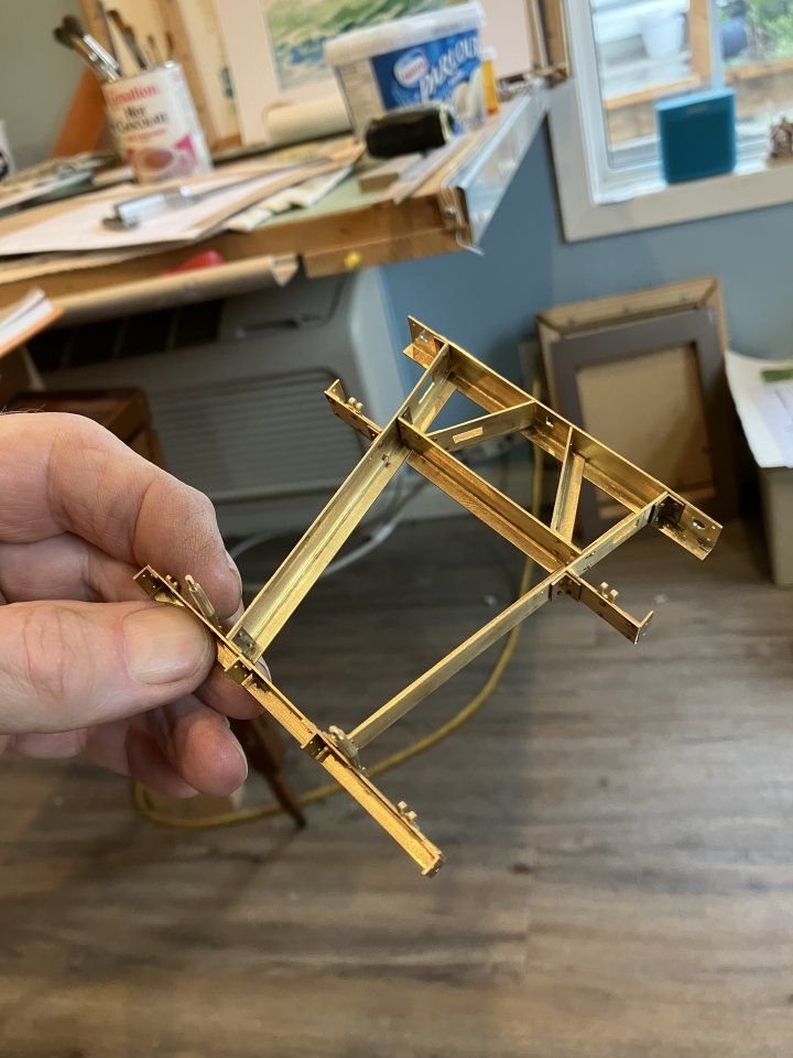
I ended up with all sorts of oddball configurations of vices clamps and bars in order to sequentially put it all together in all it took a few weeks and even then a couple of time I had to chisel off a connection because I had boxed myself in or the holes did not quite line up.
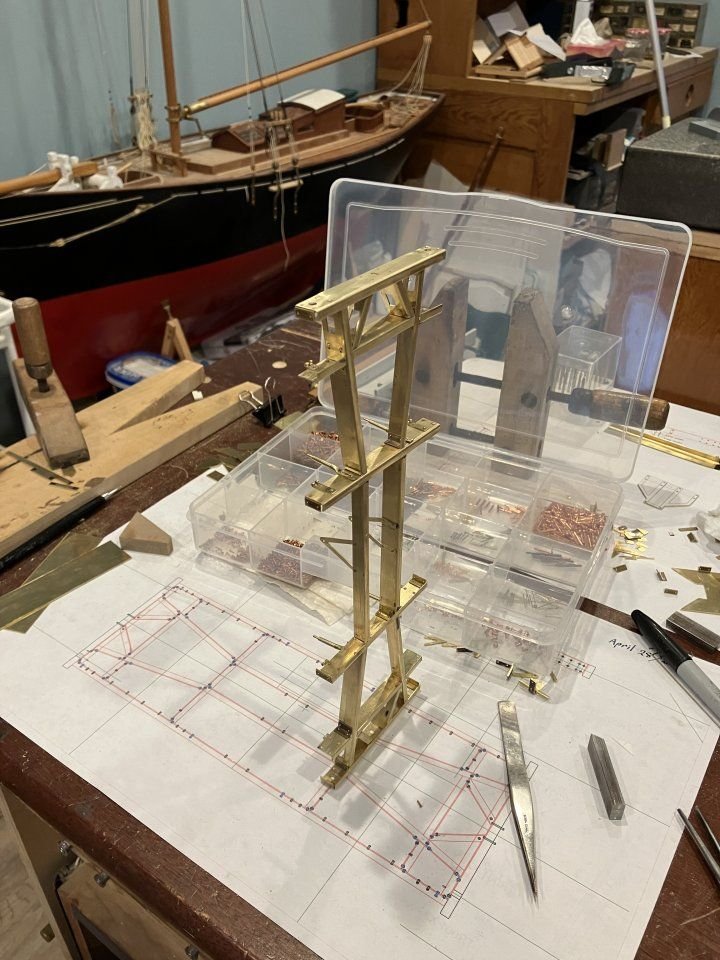
The sole bars were the last parts to add to complete the main structure and again I ended up taking a long time thinking about how to get these parts together.
Another oddball combination of vices and clamps allowed me to get the job done. (where are those nano robots when you need them?)
we are getting there......
to be continued
Michael
-
OK, here is what has been occupying my muse recently. It is a parcel van that is for Gauge 3 (63mm or 2.5 inch between rails) I challenged myself to attempt to build it using the same processes as the original with obvious substitutions regarding some of the materials for ease of building in some areas and for economical reasons, using what I had on hand rather than purchasing more materials.
I did start building this model at the Gauge 1 scale (45mm or 1.75inch between rails) but changed after getting bogged down with wanting to make the undercarriage fully working including brakes.
This is as far as the first model went, as many will already know I have no problem starting things over or changing up elements.
Next was to make the metal structural parts for the frame this meant making a bunch of scale 3 inch by 9 inch angle, I cut strips of .020" brass and folded them on the brake.
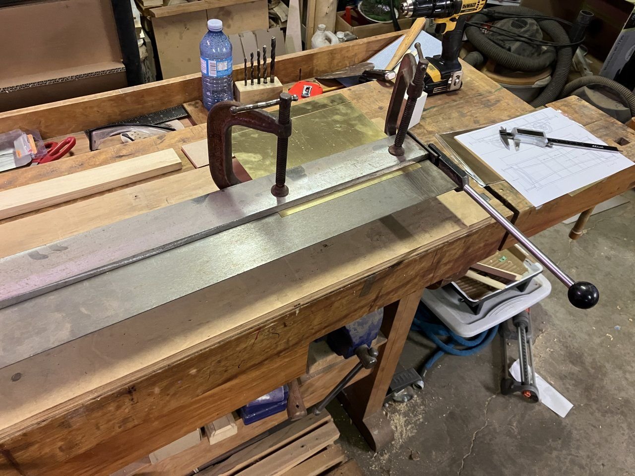
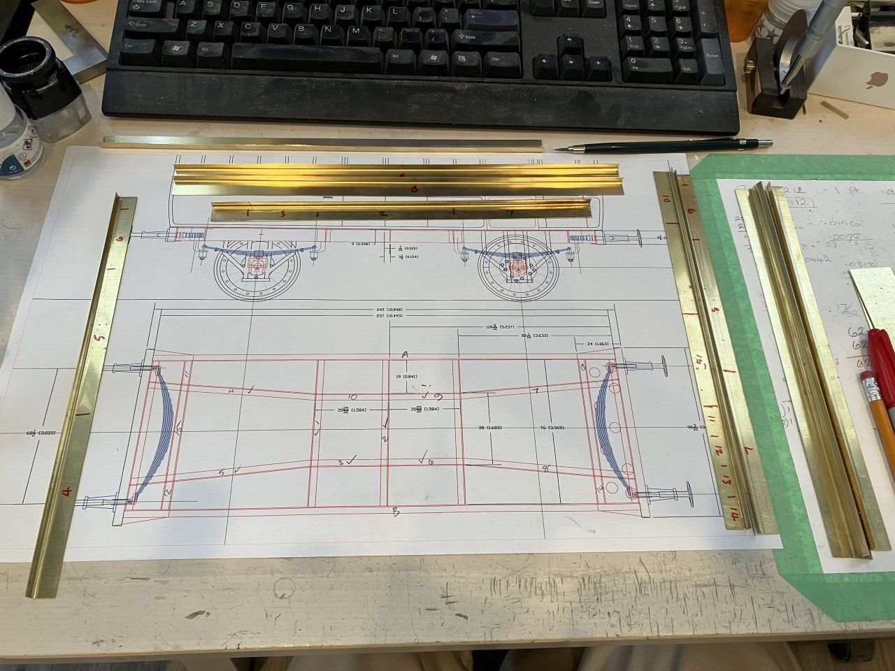
The angle needed more work to get it a bit more sharp in the corner.
to be continued.
Michael
- wefalck, Old Collingwood, Haliburton and 21 others
-
20
-
 4
4
-
Good morning everyone, I have not stopped building models just have been busy with my masonic duties I am again the Master of my lodgeand have other duties in some concordant bodies. What little time I spend in the workshop these days requires walking past the cutter which sits waiting patiently for my energy to return to it. I have been doing little work on my model railway endeavors particularly an 1876 great western parcel van which has been particularly challenging. I could post a picture or two if anyone is interested.
Michael
-
These sorts of little jigs are so satisfying because as you demonstrate they are so helpful and easy to make.
Michael- FriedClams, Keith Black, mtaylor and 3 others
-
6
-
Hi Nils one method I have found for creating curved U channels is to first anneal some thin wall brass tube then fill it with the appropriate diameter of styrene rod then bend it to the curve with finger’s then use a torch to burn out the styrene the file away the top slowly. And it would also work by just filing the top without the burning anyway.
Michael
- Mirabell61, Canute and Keith Black
-
3
-
Hi Nils just finished going through your build, wonderful creative work. I’m amazed by how fast you get the work done.
Michael- Canute, mtaylor, Retired guy and 1 other
-
4
-
Great to see another one taking shape Mark.
michael
- druxey and Mark Pearse
-
2
-
Love the lines drawings Keith, it is so satisfying hearing a pencil slide across the paper! And congratulations on the new addition to your family keen looking lad.
Michael
- KeithAug, Retired guy, Keith Black and 1 other
-
4
-
-
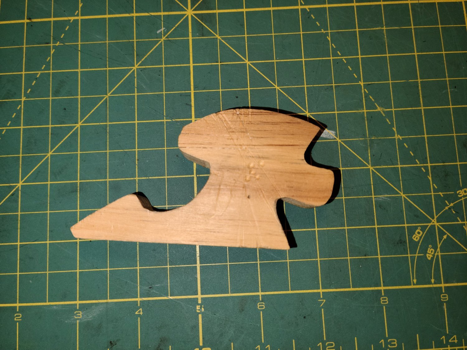
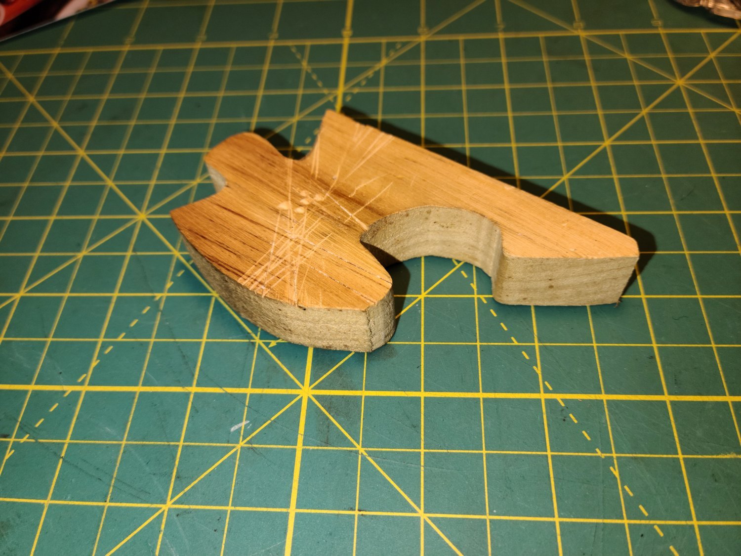
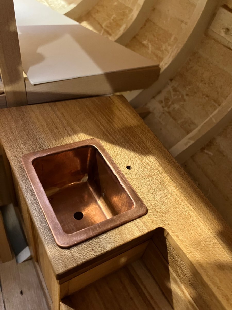
Starting the back of the galley now.
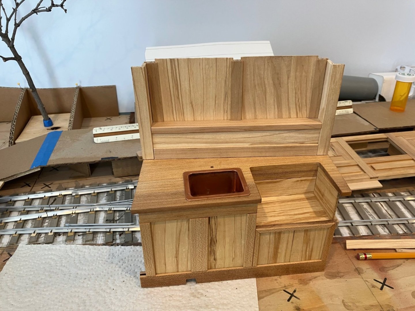
It is easier to work on it outside of the hull, l am amazed at how nice the maple that I cut from the big log 50 years ago still works and planes up with such a lovely lustre. I’m guessing it is because it has been air dried.Michael

-
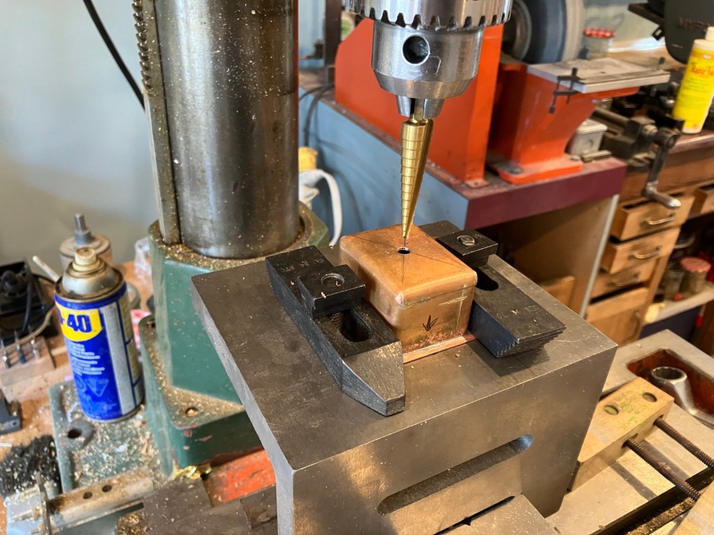
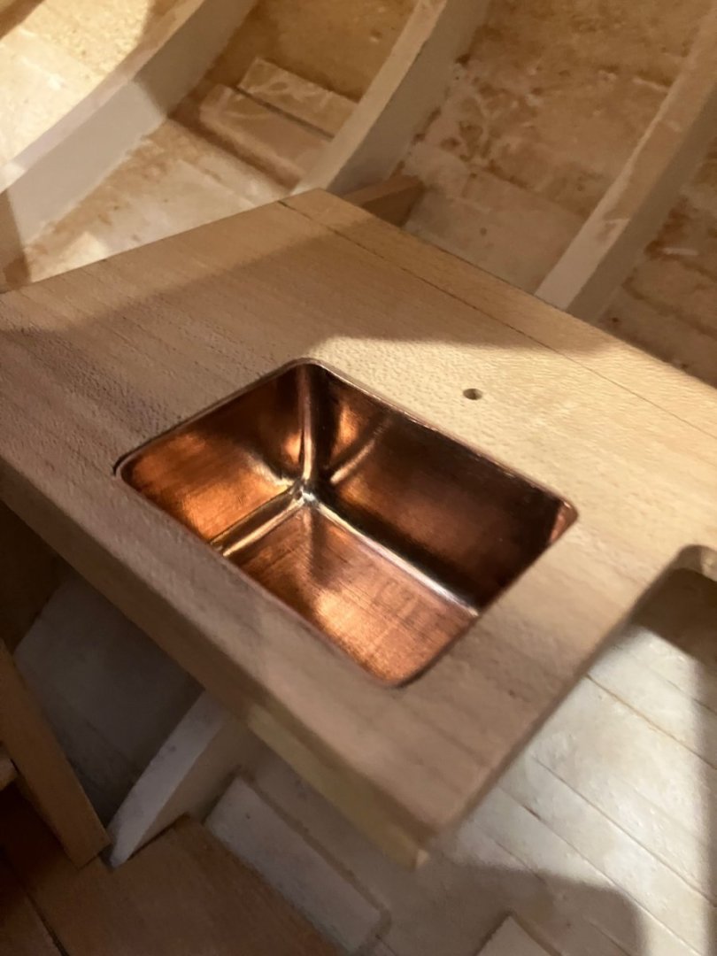
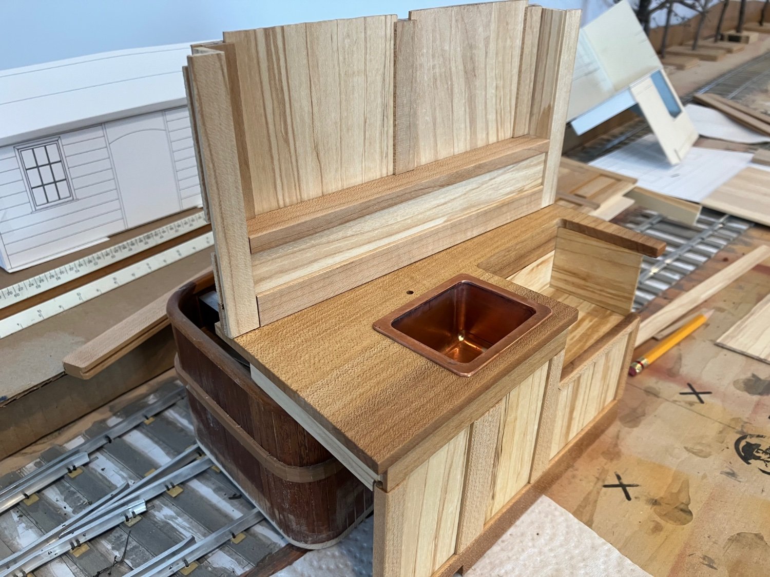
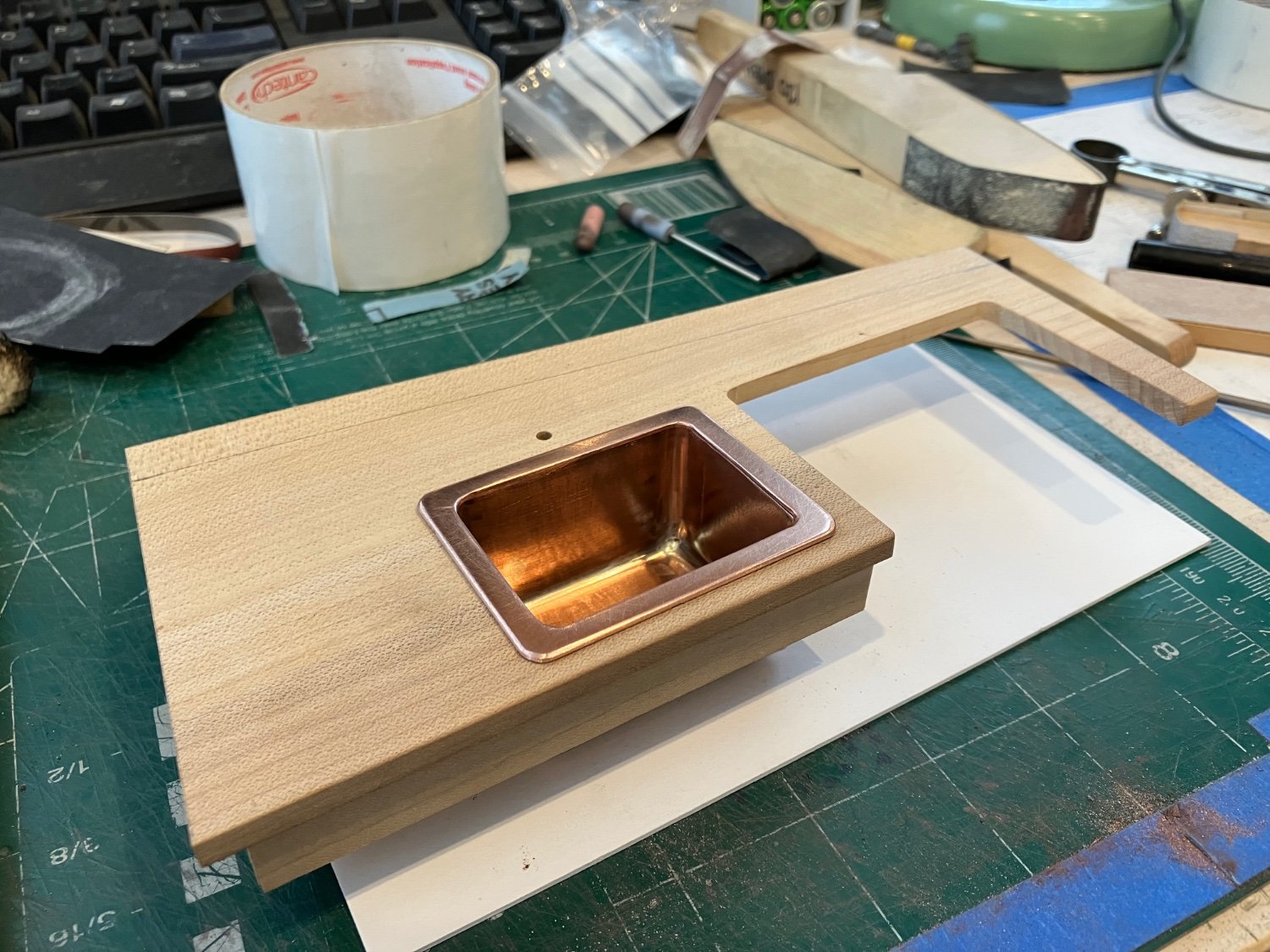
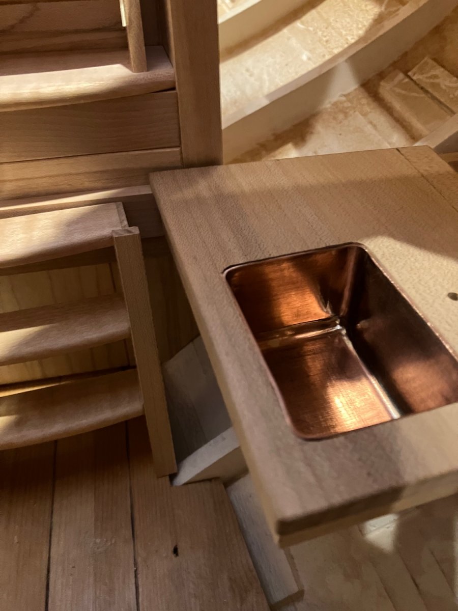
Thanks Tom I appreciate that. Thanks to everyone for your kind comments. I did some more work on the galley and have soldered the top to the sink and used the sheet metal drill for the drain pipe.


I have given the wood a good coat of tung oil and will give it another coat later.
Michael
-
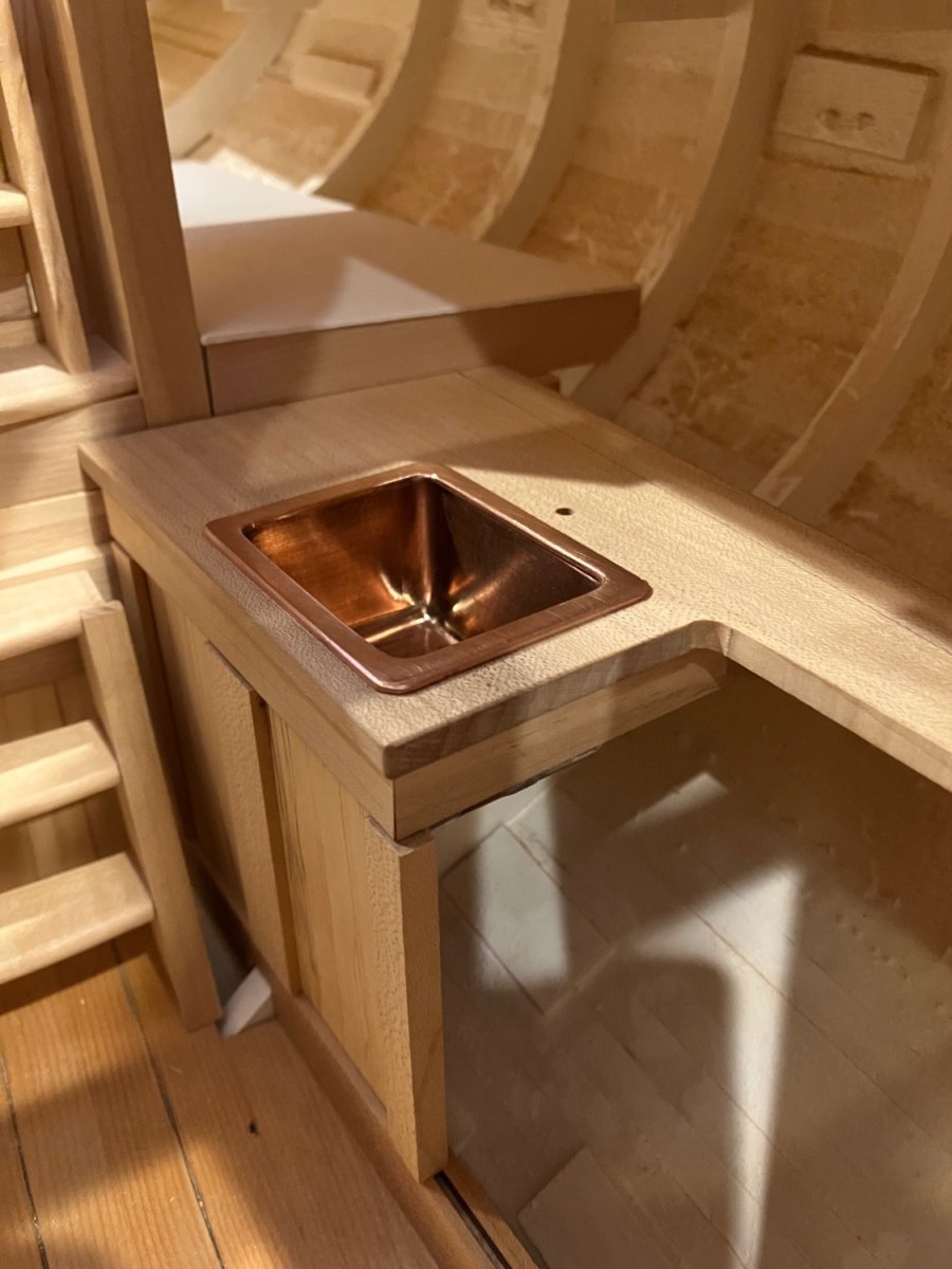
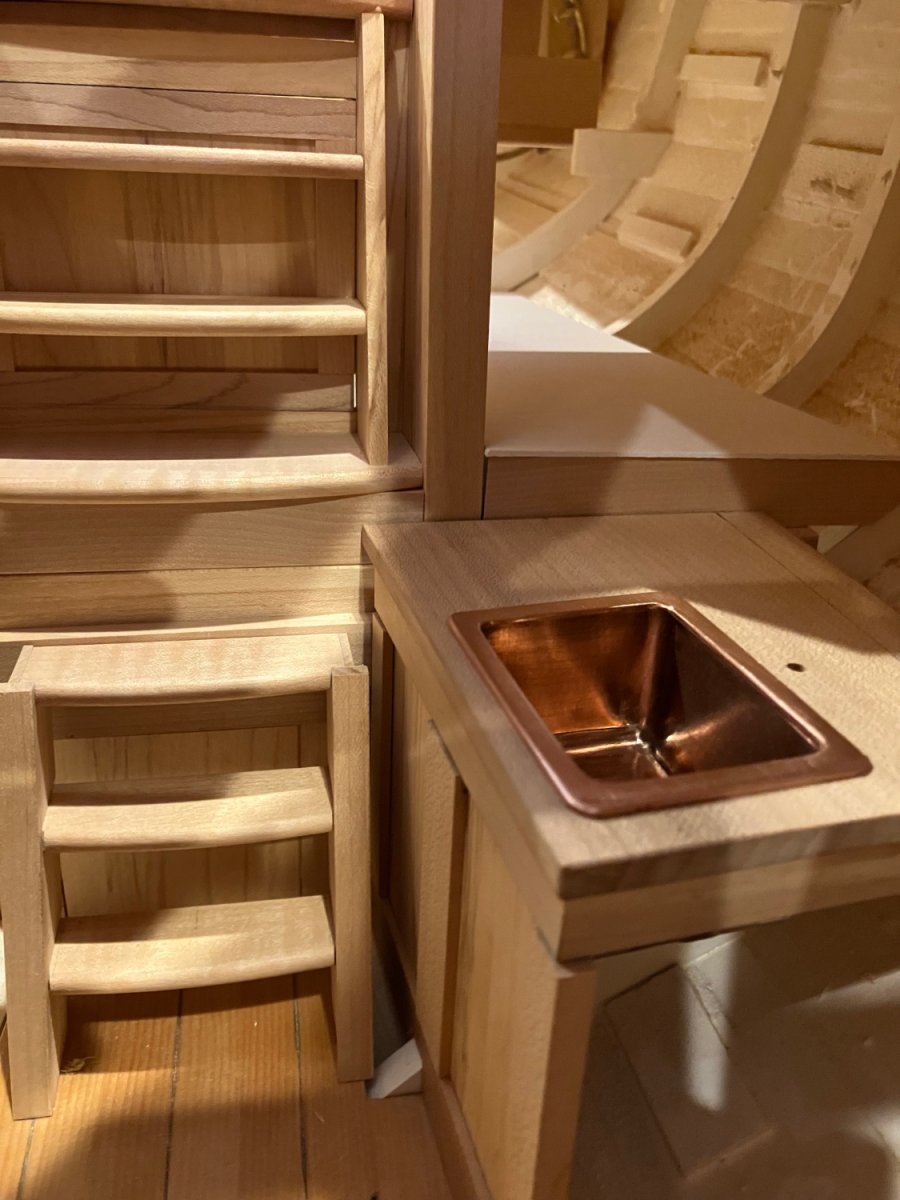
Fiddling with the galley cabinets today.


michael
- MAGIC's Craig, JpR62, KentM and 18 others
-
21
-
-
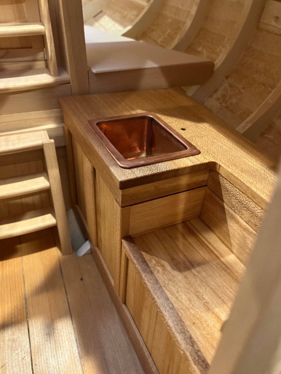
The lip is now cut and rounded on the edges

I will be raising the top when I get it back in the boat.
Michael
- Wintergreen, Mark Pearse, wefalck and 15 others
-
18
-
On 6/6/2022 at 3:13 PM, Richard Dunn said:
Ha, yeah I bet
The answer is yes but its grown for the purpose of marine fitouts, many of the super yachts still use it although it's a 5mm veneer not solid so it goes further.
Anyone can correct me if I am wrong but nowadays there are products to keep teak in good order instead of washing and scrubbing, and those that have it can afford to pay someone to look after it.
The burmese teak is what they use nowadays still (Tectona Grandis).
There is an alternative wood that has been used in place of it for several decades now and that is Iroko, its horrible stuff, we used some on a boat 20 years ago and its terrible to work, it also has dust that causes your throat to close, its very course grained and splintery stuff, it shares the oily nature of teak though which is why they use it.
Mahogony depends what species, their are over 30 species of mahogany, but the one i think you are referring to is Brazilian mahogany or Swietenia Macrophylla its been the staple for guitar builders for centuries for necks and bodies.
thier is also sepelle and many others which are still grown for the purpose but solid has become harder to get as veneer is seen as a better usage and less wasteful way of extracting the wood.
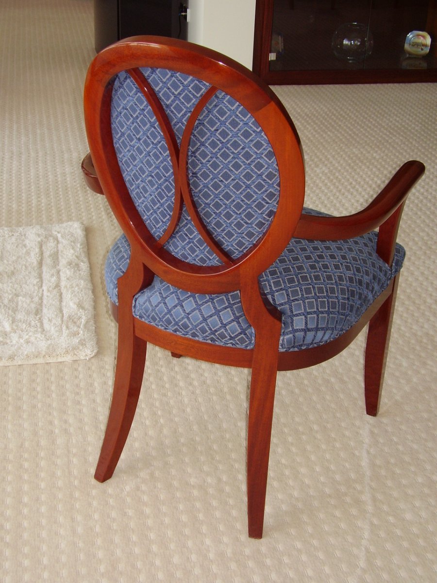
In Australia we have a few identical looking timbers that are actually better, Queensland maple being the most common, its beautiful stuff and you cant tell the difference. here is a chair I made with it, as you can see it looks like Mahogony.
Anyway I don't want to hijack this post.
Lovely work Richard also the cabinet in your earlier post. I am always on the lookout for salvageable wood for my model projects, it always breaks my heart to see an old house being crushed into matchsticks by huge machinery when much of the wood used could still be salvaged! The time is money myth will become apparent one day, but I digress.
I am still using some of the eastern sugar maple that I acquired in 1973 as a six foot long green log after slabbing it up into quarters after taking a three inch plank from the centre for a coffee table and air drying the rest. It is what I am using for the interior of my Bristol pilot cutter.The deck is close grained salvaged old growth clear Douglas Fir.
michael
-
Hi Rob just catching up with your work, nice mod on the bow.
The water reminds me of my immigration journey from the UK back in September 1967 we were on the Cunard ship the Sylvania during a force 10 for three days in the North Atlantic. 40 foot waves.
Michael
-
Keith , having spent the last hour and a half starting at the beginning, it looks like a marvelous project. I will most certainly be following along and gleaning tips from your ingenious problem solving skills. The comment about the breakfast counter made me laugh. It looks like you will have some fun with the bright-work and all those panels.
Good to hear you are well, and getting stuck into the prep for the start of keel laying.
Michael
- FriedClams, MAGIC's Craig, mtaylor and 2 others
-
5
-
Just need to solder the top lip on and drill the hole for the drain the the sink should be ready, presently the countertop is at 28 1/2 inches I am wondering if it is a bit too low.

Michael


HMS Bellona 1760 by SJSoane - Scale 1:64 - English 74-gun - as designed
in - Build logs for subjects built 1751 - 1800
Posted
Mark having just spent the better part of the morning catching up with your work on this amazing model, I fell like going and sitting in the corner and rethinking my approach to all things model related. Your tenacity to solve the methods of construction and details are enviable, I wish I had the patience.
Have you found a bit of proper English boxwood yet? if not send me a pm as I have a reasonable amount still and depending on the size of what you need I could send you some.
I have really enjoyed catching up on your build, love all the ways you use your tools and organize them as well.
Michael