gjdale
-
Posts
4,894 -
Joined
-
Last visited
Content Type
Profiles
Forums
Gallery
Events
Everything posted by gjdale
-
 This is a wonderful thing you are doing Bug. Good on you for taking this on - I know you will do Augie proud.
- 2,191 replies
-
- 8
-

-
- confederacy
- Model Shipways
- (and 1 more)
-
I have this kit in my stash too, so I might pull up a chair and follow along. Looks like you're off to a good start already.
-
Phil, I'm sure that any wood filler will do the job for you, but try to use one that claims not to shrink. A product I came across recently that works very well and is easy to use, is Durham's Rock Hard Water Putty. It comes in powdered form, which you mix with water to a consistency of your liking. Once dry, it sands very easily, producing a dust that is similar to talcum powder. It leaves a beautifully smooth finish for painting. If you are trying to simulate a steel hull, then I'd recommend using an undercoat. While there are as many opinions on paints as there are brands, Krylon does a range of spray cans for a variety of metal finishes that look really nice.
-
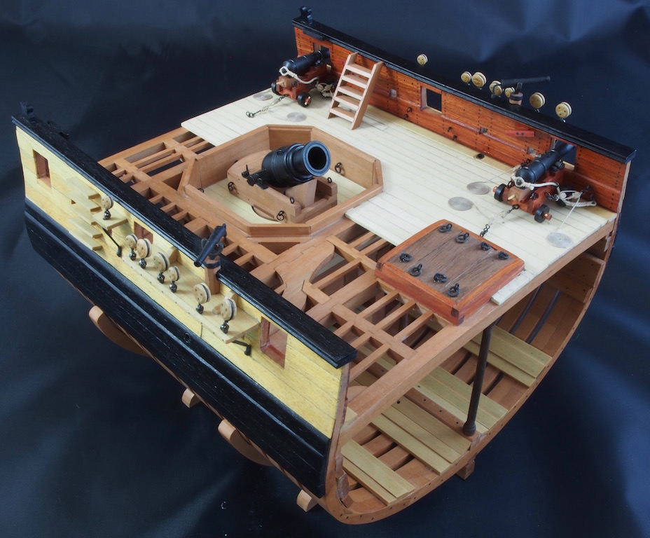
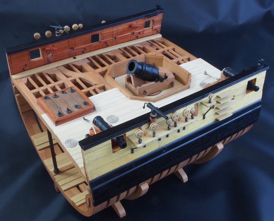
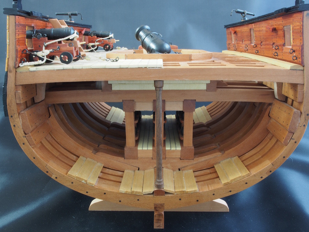
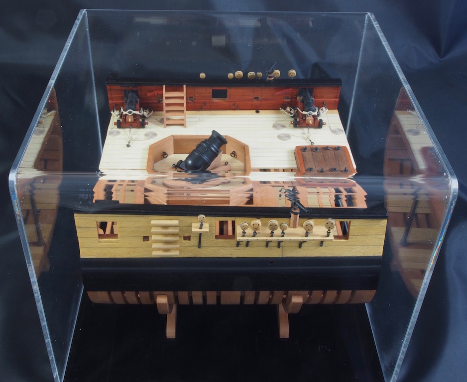
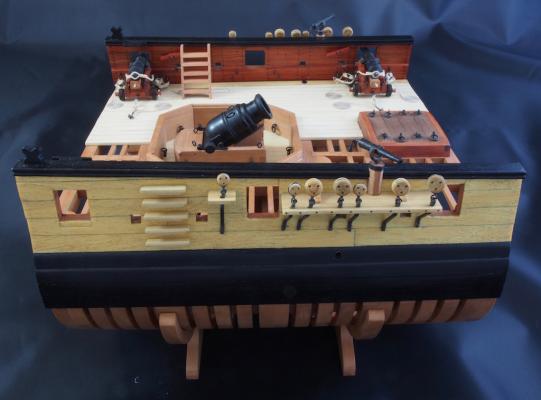
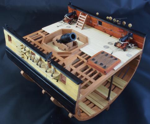
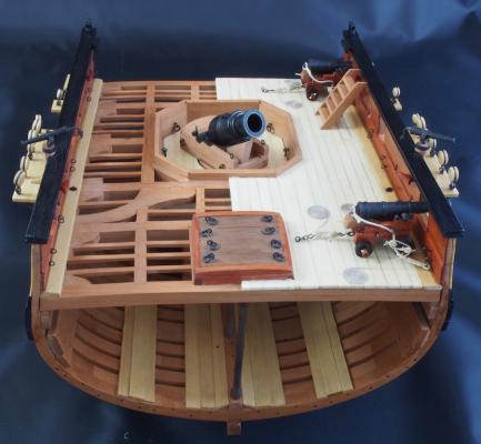
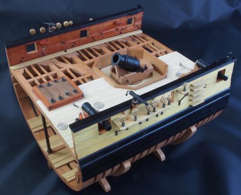
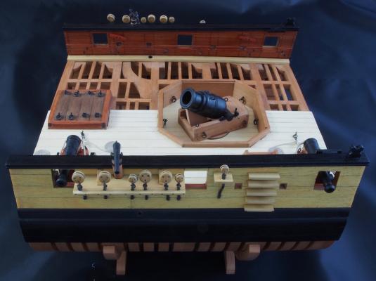
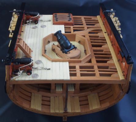
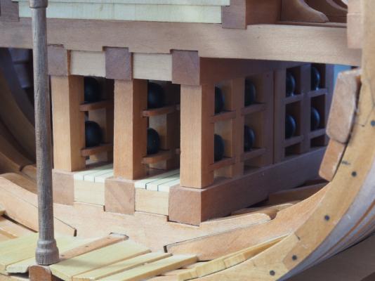
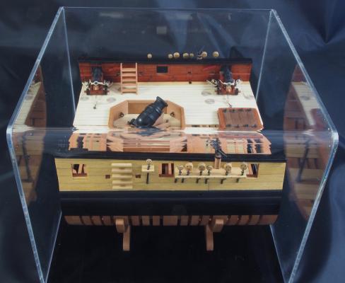
Once again, thank you all for all the kind comments and the "likes". Finishing Up Well, I decided not to go ahead with the Mortar Pit Housing, for the reasons previously described. In the meantime, my display case has been finished and I picked that up this week. As usual, he has done an excellent job with this. The case is 3mm Perspex, with the front/top/back being all one piece bent to shape. This gives a nice clean look. The base is gloss black Perspex, which he has routed to provide a nice rebate for the cover to sit on. I think it looks great! Yesterday I made the final version of the display cradle, using Pear stock. Just as Mobbsie found, our timber supplies couldn't quite cater for the size as drawn by Jeff Staudt in his excellent set of drawings. My recollection of my discussion with Jeff Hayes (HobbyMill) when I was ordering the timber, was that he couldn't quite get the width required, although he did manage to get close. Instead, following Mobbsie's lead, I trimmed down the drawing to fit within the timber that I had available. The effect of this is to make the stand a little less chunky, which makes it blend into the frames a little more - so it's probably a good thing. With that, I’m calling “done” on this project. It has taken just over 15 months to complete and it has been a lot of fun. It has provided some great learning opportunities, and while it has provided its fair share of frustrations, the opportunity to work from such great drawings/plans and with such wonderful timber, have far over-shadowed any set-backs. It has also been fun building this in tandem with my mate Mobbsie in the UK. We have often discussed challenges over Skype or email before one or other of us was the guniea pig for the next step – usually Mobbsie, as he’s so much faster than I am! To celebrate completion, I broke out the serious photo-tent and lighting to try and do her justice. Even though I spent some time cleaning her up for the photo shoot, the close-ups show that there is still a bit of dust here and there. Anyway, here she is in all her glory. The last photo shows her in her case at last. Before I close off this log, a few thank you's are in order. Firstly to Jeff Staudt for producing such an excellent set of drawings that even a first-time scratch builder can make a decent job of it! Secondly to Jeff Hayes of HobbyMill for his patience and advice when working through the timbering needed for this project, and also for producing such wonderful quality timber to work with - and for being so generous in his allowances! I swear I have enough timber left over to make another whole model!!! I'd also like to thank my build-buddy, Mobbsie for agreeing to take on this project with me. It has been a lot more fun being able to toss ideas around together when facing a particularly challenging part. On that note, I'd also like to particularly mention the assistance provided by Rusty. I have a very lengthy set of PMs exchanged with Rusty, as whenever I got really stuck I would refer to Rusty's log and if the answer wasn't there, I'd PM Rusty with a question or follow-up and he never let me down with his replies - thanks Rusty. And of course, I'd like to thank everyone who has followed along with this journey. Your support and encouragement means more than I can say. Thank you one and all. Now, it's time to dig out that other "concurrent" project - the Dumas Chris Craft RC build. It was supposed to be built in tandem with this cross-section, but in reality hasn't been touched since about March last year. There is a link in my signature block if anyone is interested in having a peek at that one.


- 456 replies
-
- 25
-
-
- finished
- bomb ketch
- (and 2 more)
-
Cutter Cheerful 1806 by rafine - FINISHED
gjdale replied to rafine's topic in - Build logs for subjects built 1801 - 1850
I can thoroughly recommend the Bomb Vessel Cross Section, Bob. The plans by Jeff Staudt are excellent and at 1:48 scale is easy enough to work with while not producing a "monster" to house on completion. I have found it to be a most enjoyable build.- 525 replies
-
- 4
-
-
- cheerful
- Syren Ship Model Company
- (and 1 more)
-
Cutter Cheerful 1806 by rafine - FINISHED
gjdale replied to rafine's topic in - Build logs for subjects built 1801 - 1850
Very nice Bob! Finish line is in sight and approaching quickly. So what IS next?.........- 525 replies
-
- 3
-
-
- cheerful
- Syren Ship Model Company
- (and 1 more)
-
At the risk of repeating everyone else - just WOW! Such ingenious fabrication, and a real joy to follow this.
-
Sorry to hear that Charlene has felt it necessary to stop work on the Bounty Jerry - she was clearly enjoying learning from you. I'm sure your build buddy will return in due course.
-
Frustrating - yes. Time-consuming - yes. Valuable learning along the way - absolutely! Good on you for your perseverance Dan. You will be very pleased you bit the bullet at this stage when you see the end result!
-
Blackening brittiana fittings ?
gjdale replied to Senior ole salt's topic in Masting, rigging and sails
Jax Pewter Black will work on Brittania castings. -
Looks like you're off to a good start Phil, and I see you're already receiving plenty of good advice. Just remember to take your time and enjoy the journey. Mistakes will most certainly be a part of the process and re-dos are simply an opportunity to do better. I look forward to following your progress.
-
Nice to see you back Harvey!
-
That's a very nice planking job so far Ken!
-
And me Bob! I have one of these stashed away with a Boxwood timbering set from Jeff. I'll be really glad to follow your progress with this.
-
Cutter Cheerful 1806 by rafine - FINISHED
gjdale replied to rafine's topic in - Build logs for subjects built 1801 - 1850
Congratulations on reaching this milestone Bob. She looks terrific, and that windlass kit from Chuck looks to be well worth the investment.- 525 replies
-
- 4
-
-
- cheerful
- Syren Ship Model Company
- (and 1 more)
-
That's looking really nice Jack. Clearly your painstaking preparations are paying off.
- 170 replies
-
- 3
-
-
- gokstad
- dusek ship kits
- (and 1 more)
-
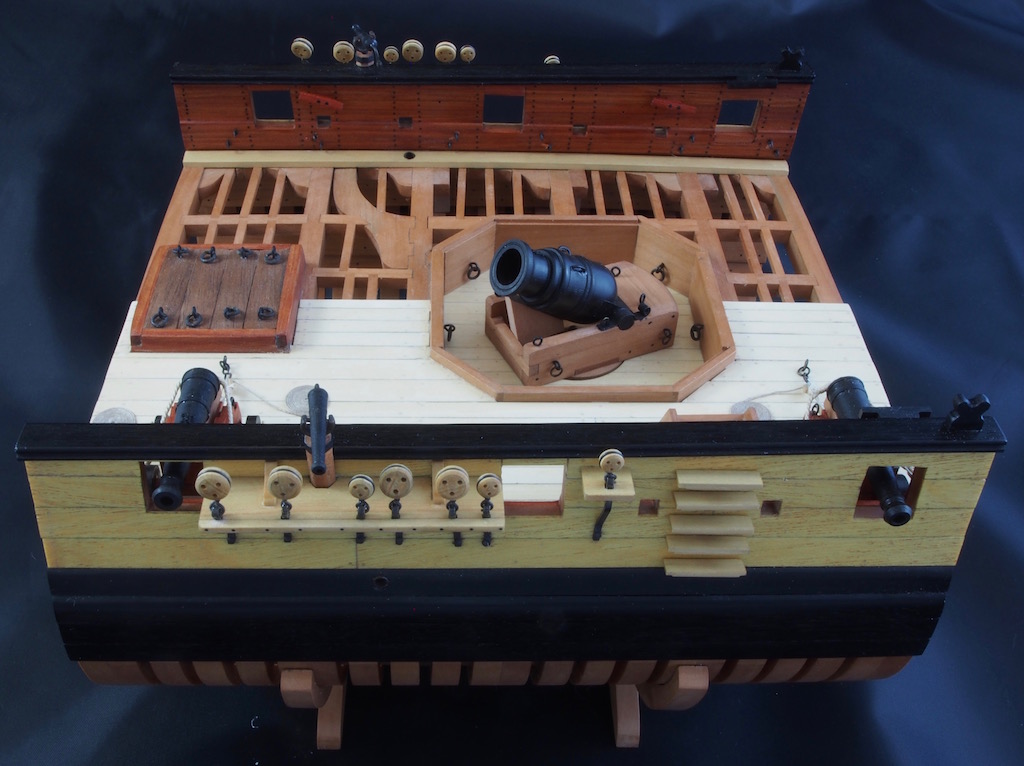
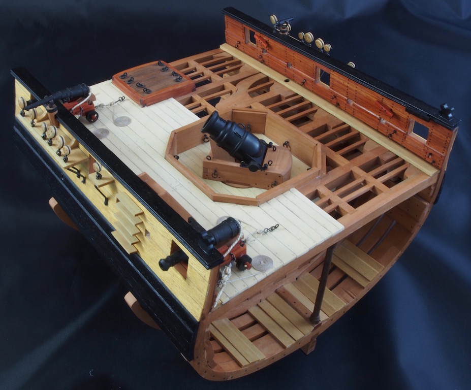
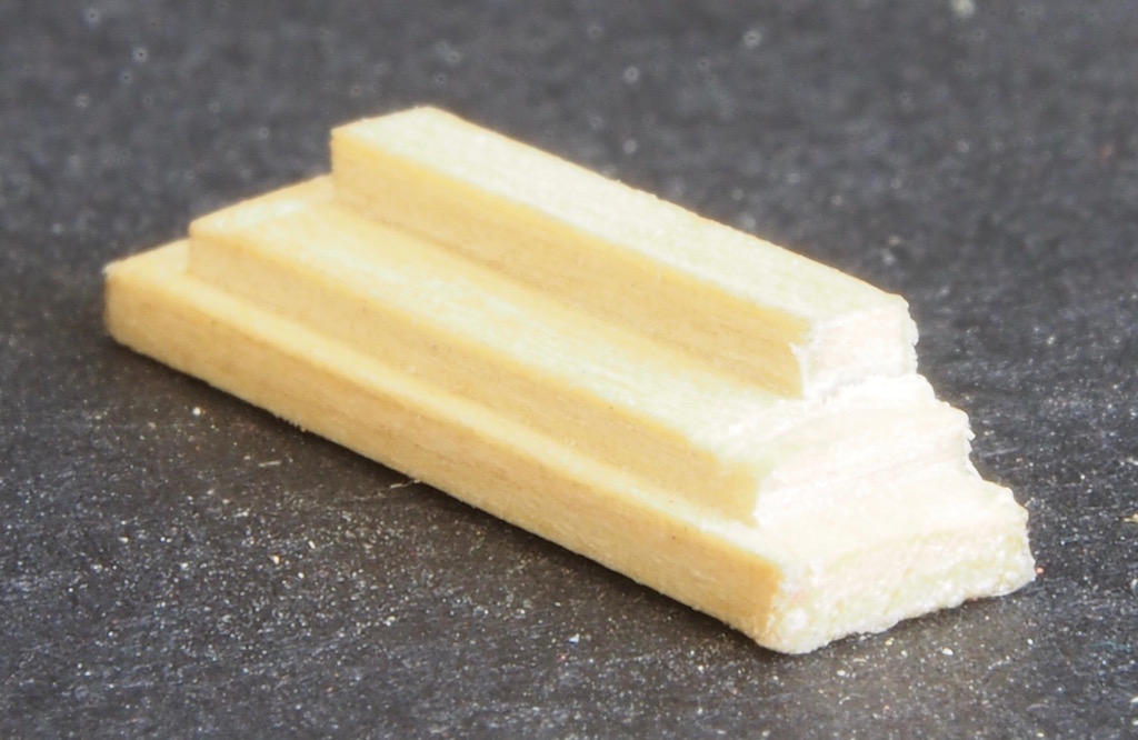
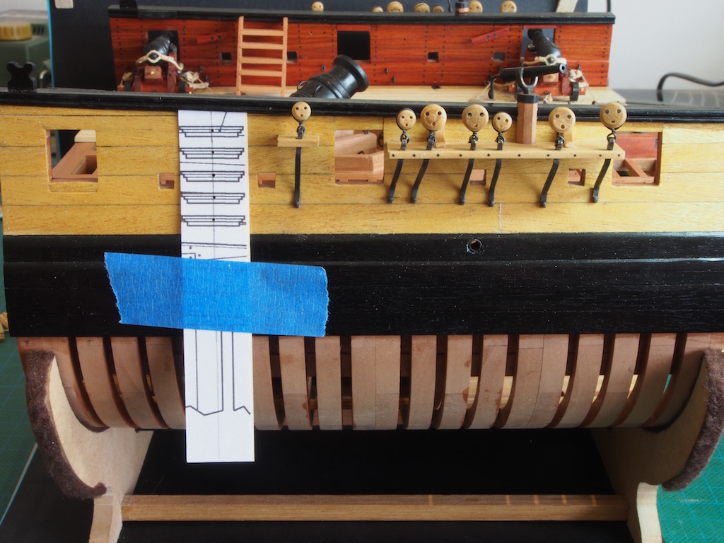
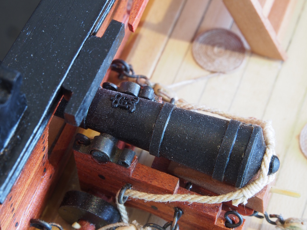
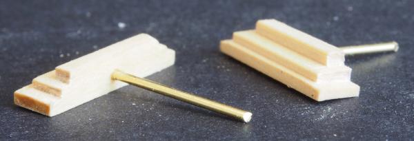
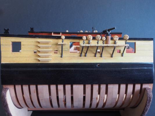
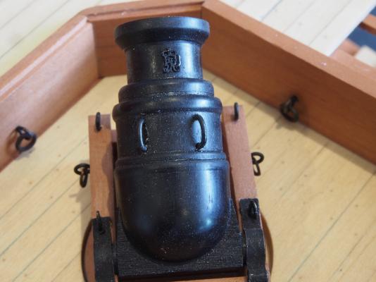
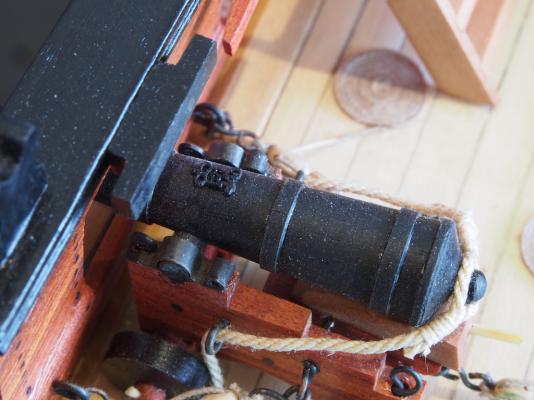
Thanks again folks for all the kind comments and the "likes" - they really do encourage me to keep striving to do better. The home straight is in sight! Entry Port Ladders The entry port ladders were fairly simple to make – once I used the right timber, and the right method. My first attempt was using 3/16” square stock Yellowheart, and using the Mill to cut the stepped profile. I quickly discovered that while Yellowheart is fine for planking, it is very difficult to use in other applications. It is very coarse grained, and very brittle, meaning that it will splinter as soon as look at you. I also decided that this task would be better accomplished using the Byrnes table saw rather than the mill – quicker, easier, and cleaner. I decided to use Castello Boxwood for the task as it still retained a pale colour to blend in with the external hull planking, and at the same time was consistent with the timber used for the Channels. These two decisions made the task very simple. The profile along the long edge of the ladder steps was cut very quickly onto longer lengths of stock. I decided to add a degree of difficulty by continuing the stepped profile onto the short edge of the steps. The pieces are too small to safely attempt this with the table saw, so they were individually cut using a chisel and finally cleaned up with a file. This last task was also much easier than I had first thought – perhaps I’m starting to develop my skills with the hand tools too! Here is what the steps looked like after profiling: I decided that they would be easier to mount on the hull if they had a locating pin, so I made up a very simple length jig for the drill press to ensure that all steps had a hole exactly in the middle of their lengths, then inserted a long brass pin “handle”. This handle was a useful holding aid while applying a coat of Wipe-on Poly to the non-glued surfaces, after which it was cut off to a more appropriate length. To aid in placing the steps accurately on the hull, a template was printed from the drawings and attached to a piece of card stock. This was taped in place on the hull while the centres of the steps were marked through with a brad point. The locating holes were then completed by very carefully hand drilling, and the steps glued in place. PVA was used for gluing, which gave ample time to ensure that each step was aligned parallel to its neighbour. Also during the week, my shipment of monograms from Chuck’s Syren company arrived – I think mine may have been the very first order placed, or if not, it was very close. I have to say that I am delighted with the product. The larger size is just right for this scale – a side-by-side comparison with the Russian-made (? or perhaps Ukrainian?) guns that Danny had given me previously showed that Chuck’s monograms were pretty much identical in size, and they also match really well against Jeff’s drawings. Well done Chuck! I gave them a coat of Floquil Engine Black prior to cutting from the sprue, and then put a tiny dab of CA glue on the barrels before placing the monograms ever so carefully with a pair of very fine pointed tweezers. This job would of course have been much easier to do prior to mounting the guns. Anyway, here’s a couple of shots showing the monograms in place on both the Mortar and Gun barrels. Unfortunately, the photos also show just how badly the model needs cleaning up prior to completion. I have been working on the "optional" Mortar Pit Housing over the last couple of days. Not sure if I will complete this yet or not for two reasons. Firstly, as I have been doing this, I have discovered that the recesses I cut into the top of the Mortar Pit are not actually the right size - I didn't appreciate at the time how everything worked together, so I went with something that looked "about right" at the time. If I had studied the plans more thoroughly, I might have realised this and been in good shape at this point. The other reason is that as far as display goes, it really needs for the Housing to be completely on or completely off - there doesn't seem to be a 50/50 option. So, I may just continue to make the parts for the heck of it, or I may get to the point where I simply call "done". I ordered the display case this week, so I've got until that arrives to finish this task, make the final display cradle/stand, and apply some Wipe-on Poly finish to the external lower hull. Oh yes, and clean the pesky dust off !!!!!


- 456 replies
-
- 21
-
-
- finished
- bomb ketch
- (and 2 more)
-
Sorry to hear about the Half Moon, Sjors, but do I recall correctly that Anja has a scratch build Hannah package waiting in the wings? Could be just the excuse needed to start on it!
- 1,616 replies
-
- 3
-
-
- caldercraft
- agamemnon
- (and 1 more)
-
Ken, You could always try "ebonising" your wood instead of painting it. The process is described quite well in this video:
-
Very clever indeed Nils - they look great!
- 2,625 replies
-
- 4
-
-
- kaiser wilhelm der grosse
- passenger steamer
- (and 1 more)