Hubac's Historian
-
Posts
2,943 -
Joined
-
Last visited
Content Type
Profiles
Forums
Gallery
Events
Everything posted by Hubac's Historian
-
 Hi Dan, Superlatives are all spent, at this point, but the project remains of tremendous interest and I really appreciate your sharing of technique for the stropping and seizing of blocks. Your visuals go a long way toward de-mystifying this for me. Thank you!
 -
Thanks Druxey! The top would definitely have been black. Conventionally, speaking, gold or a simulated gold would have been likely for the moulded edge, but I am sticking with the latter 17th C. mandate to reduce gold work. I will match the ocher on the outboard profile, and save gold strictly for ornaments. I have chosen this approach largely for the high-contrast impact that allows the ornaments to really stand-out.
- 2,444 replies
-
- 3
-

-
- heller
- soleil royal
- (and 9 more)
-
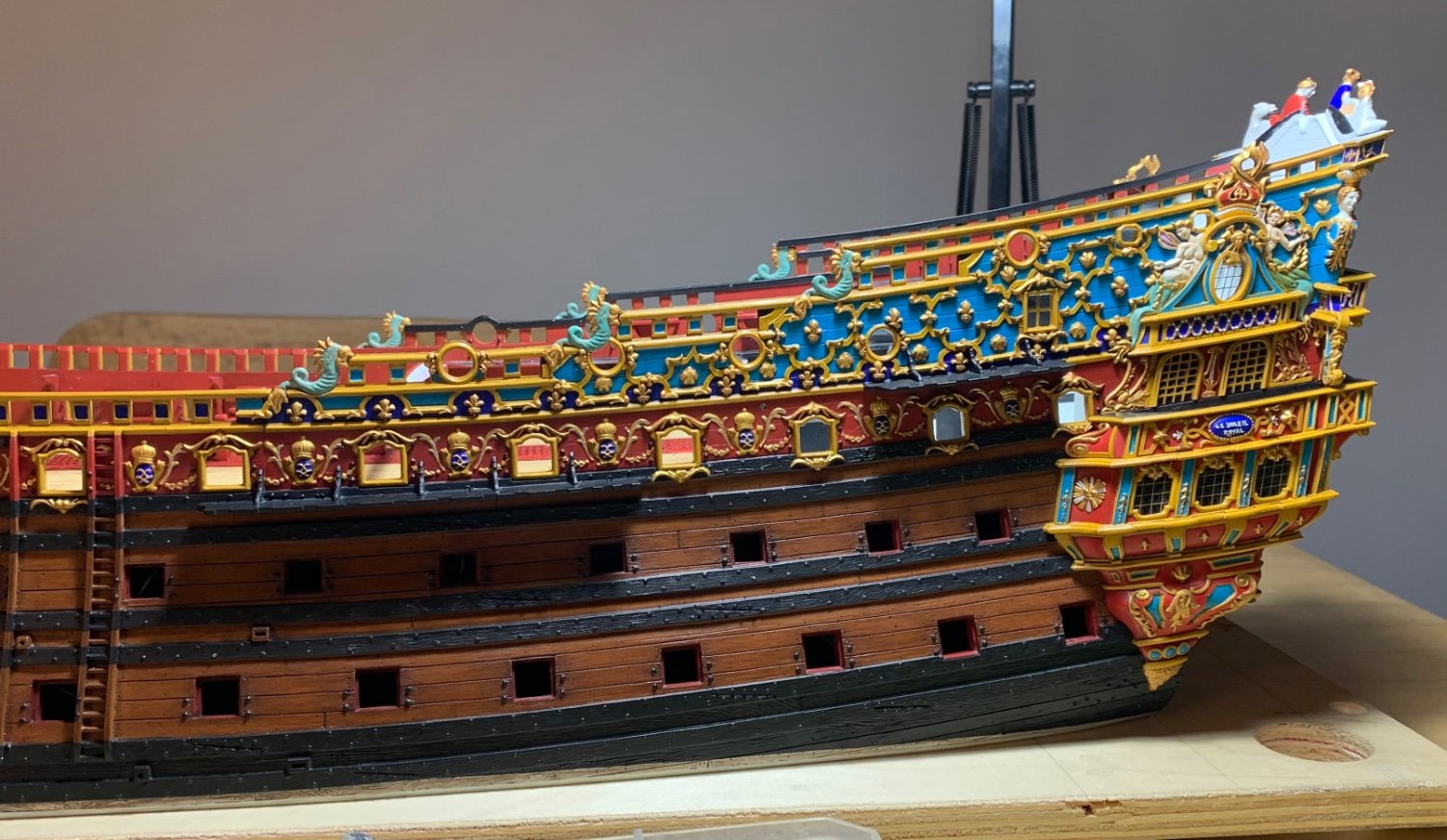
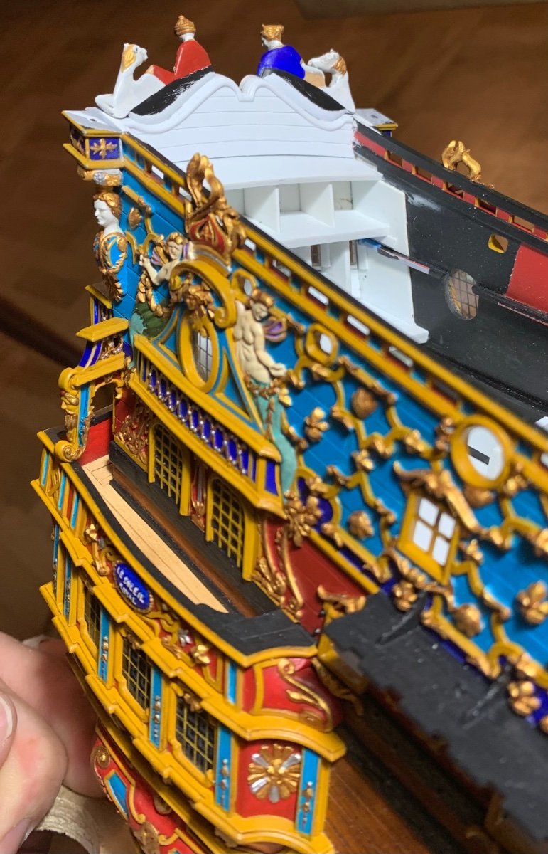
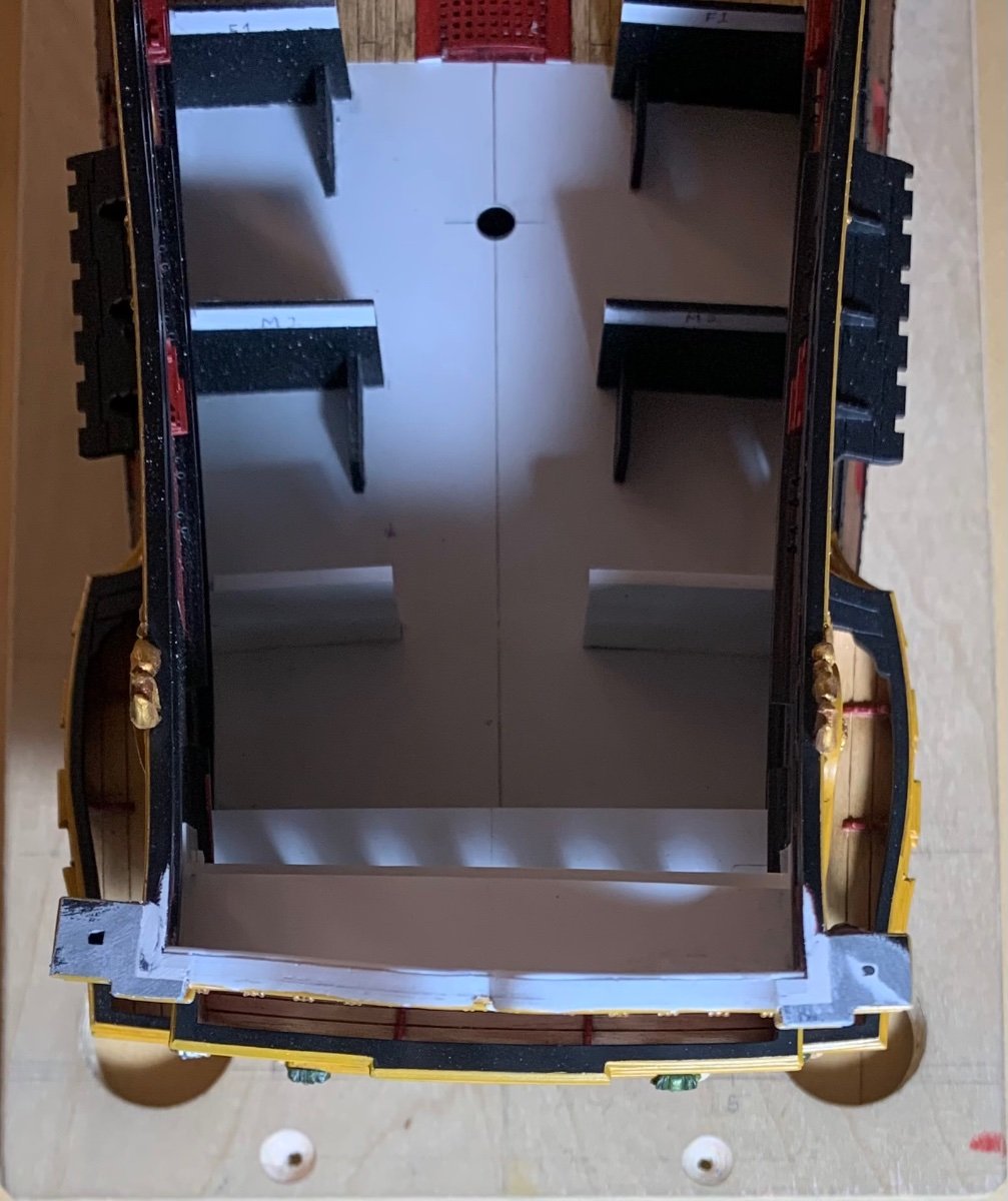
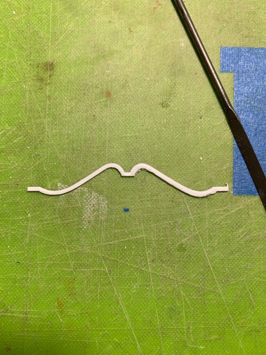
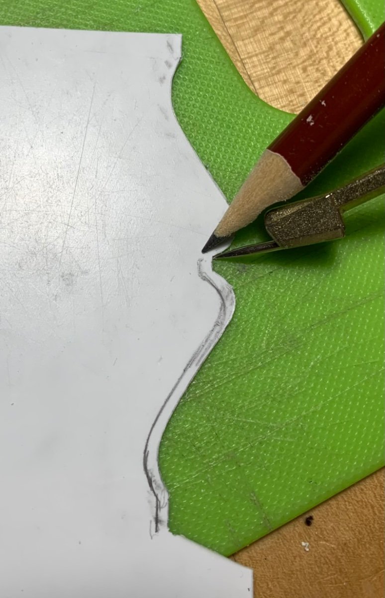
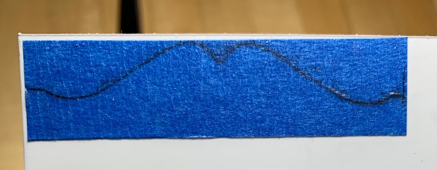
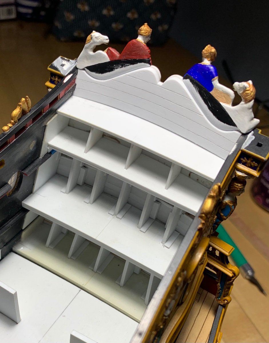
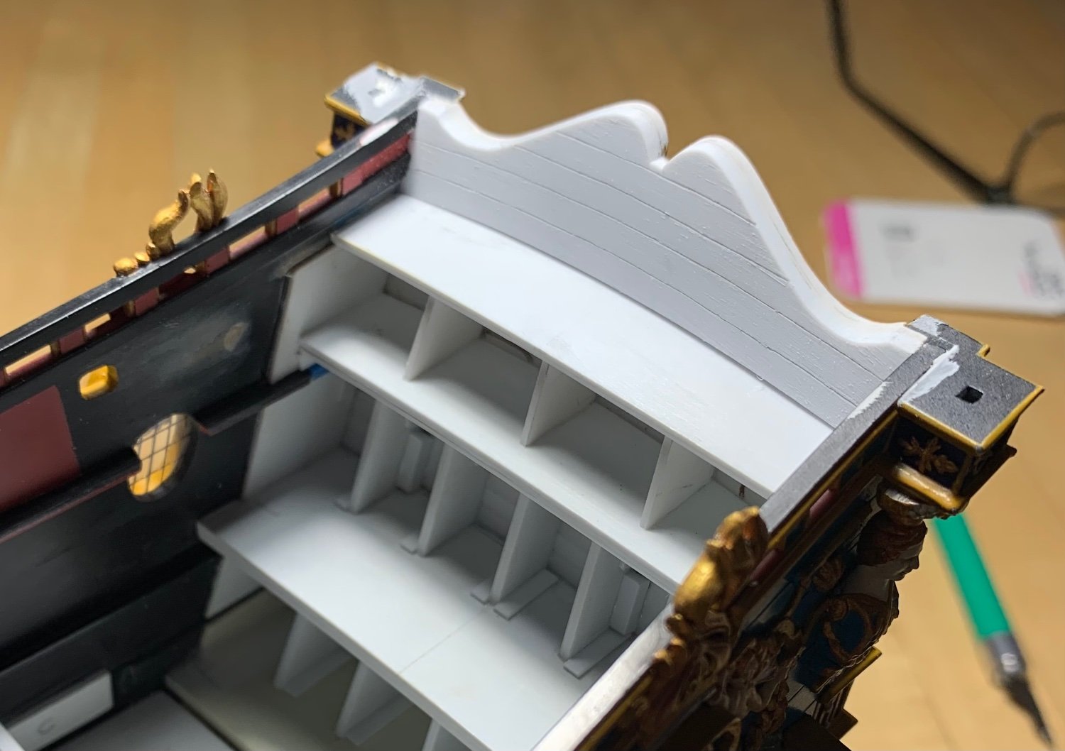
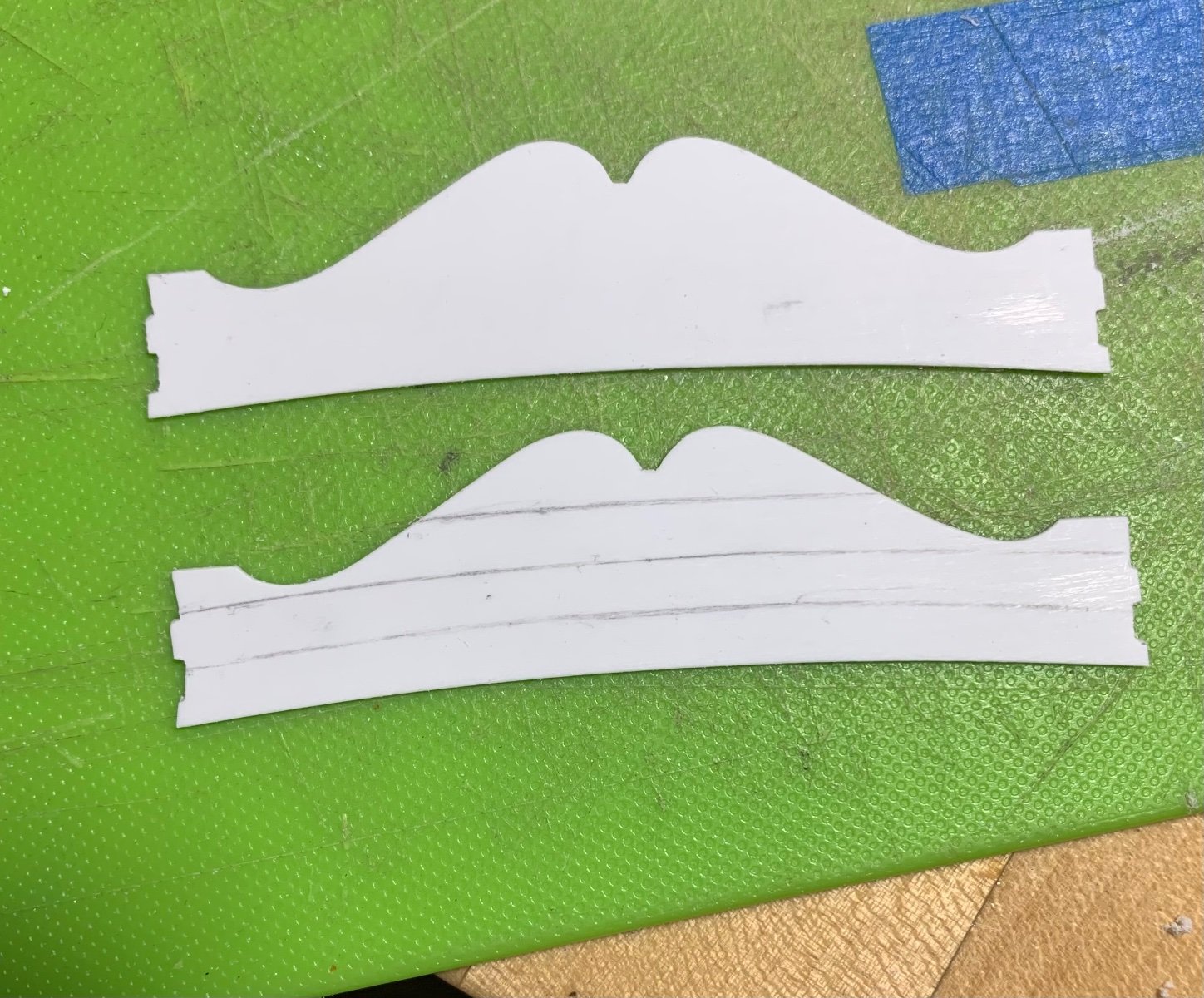
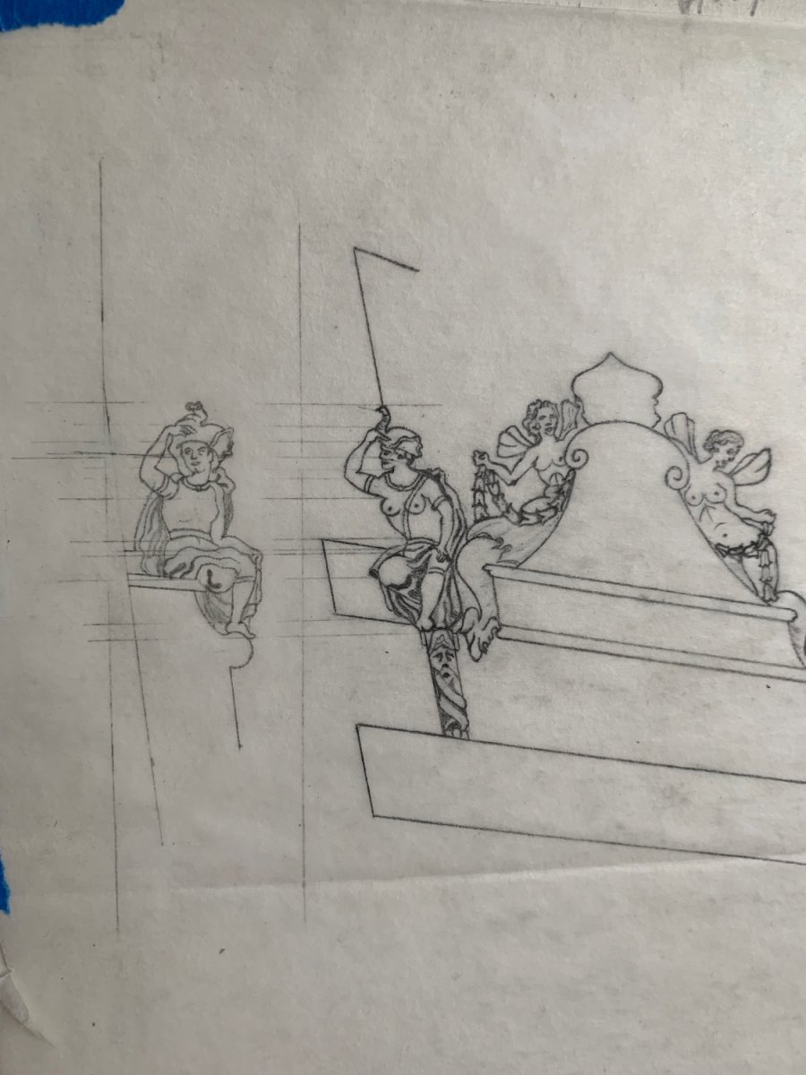
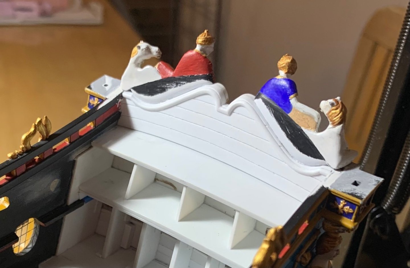
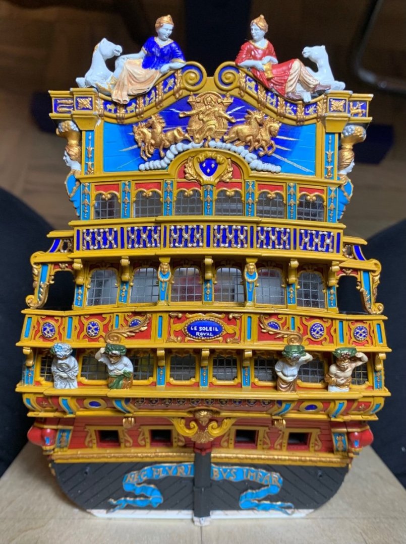
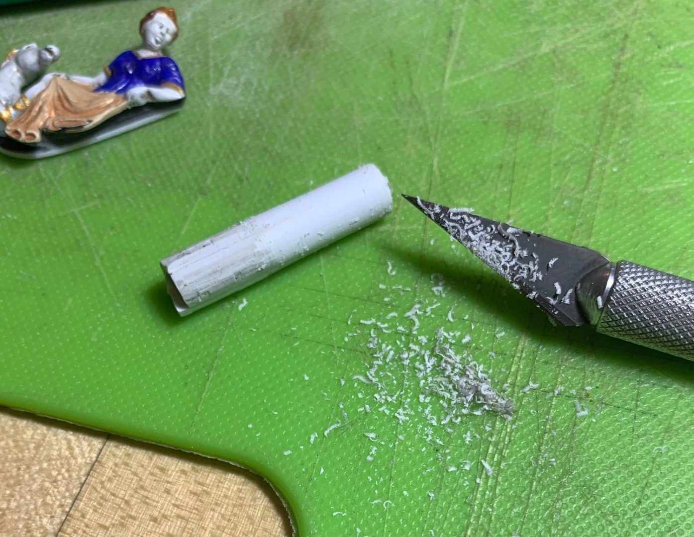
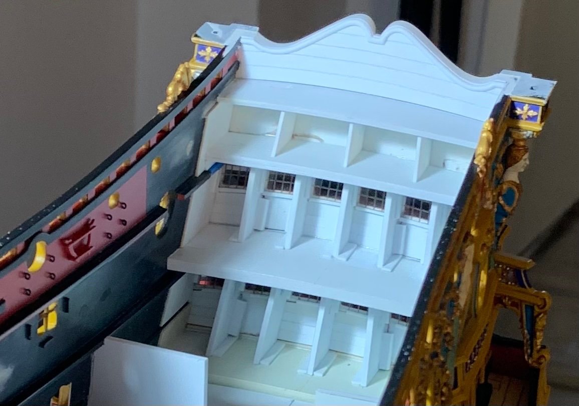
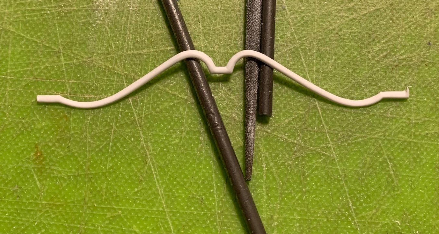
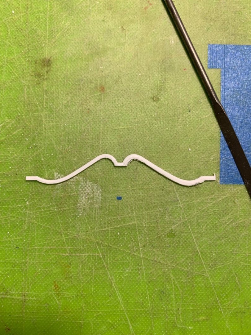
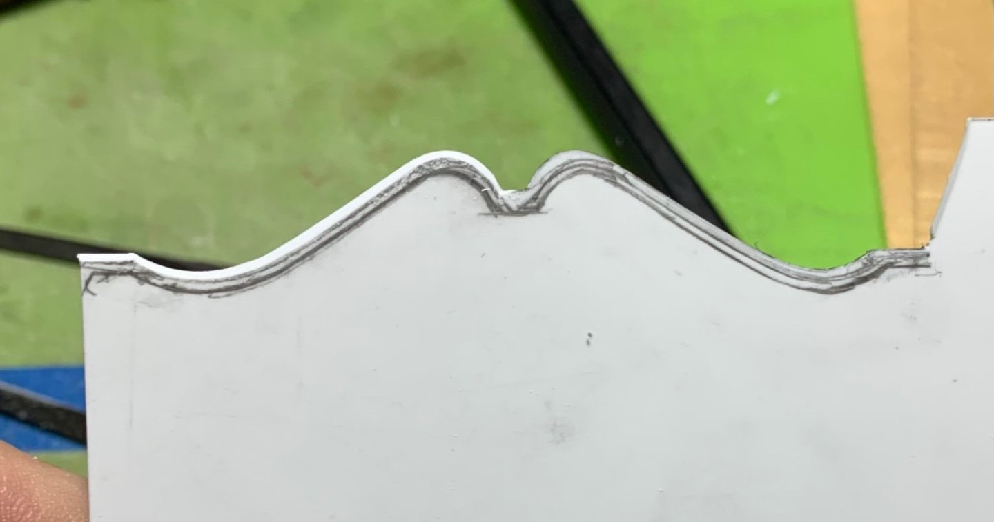
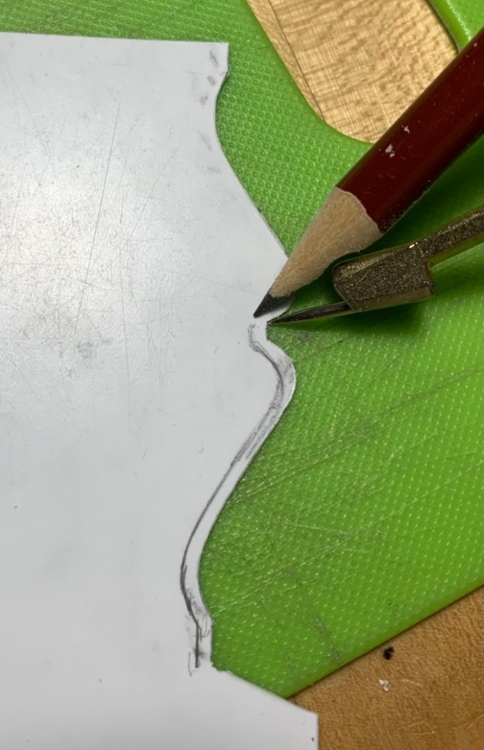
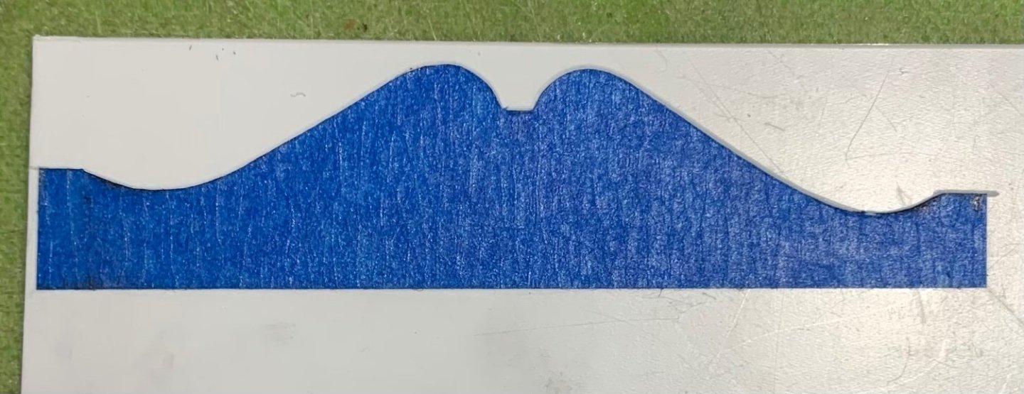
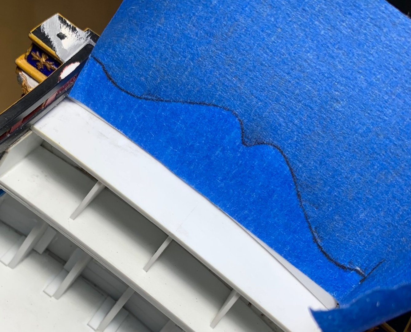
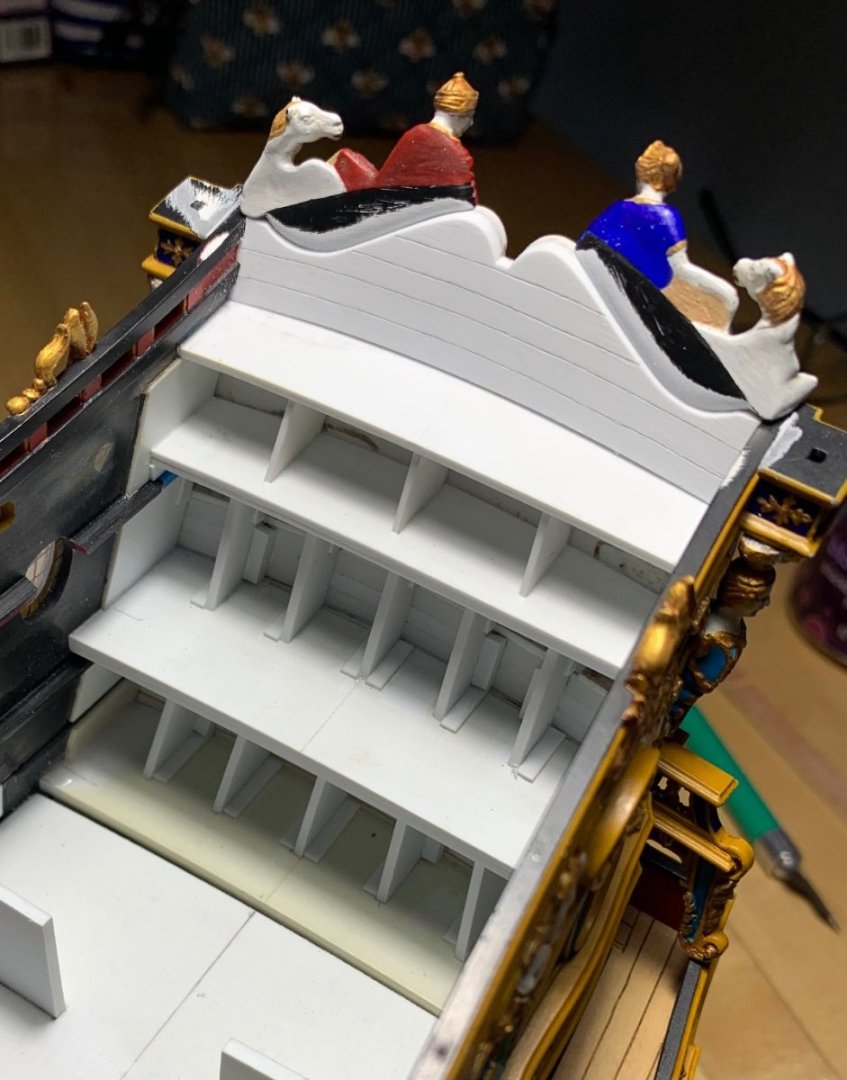
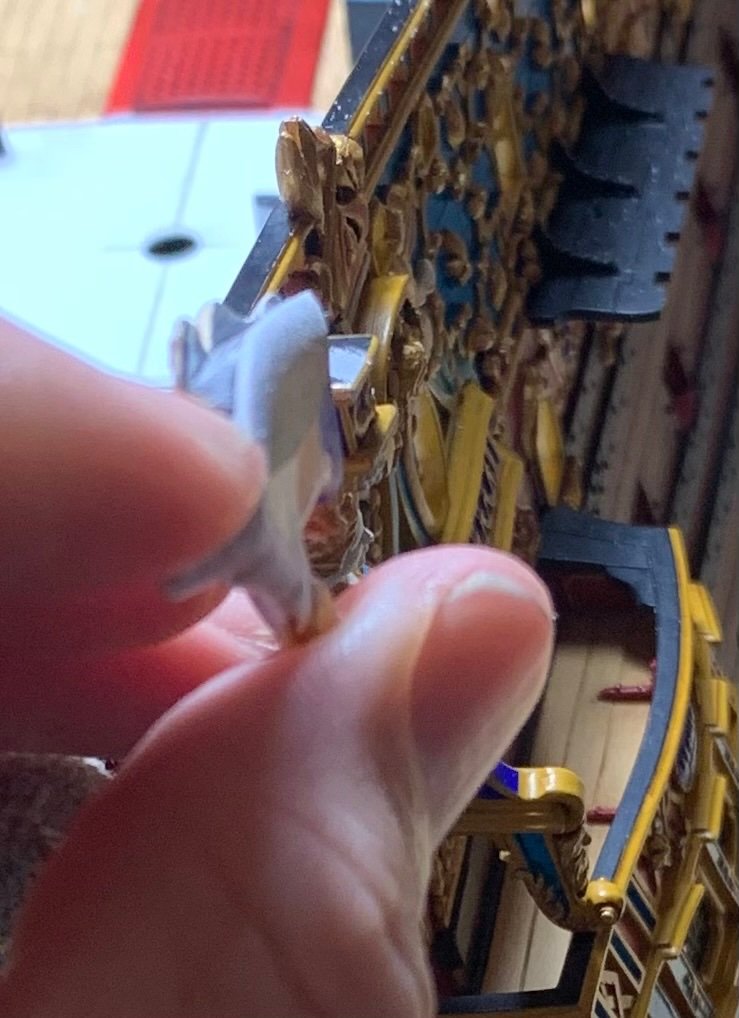
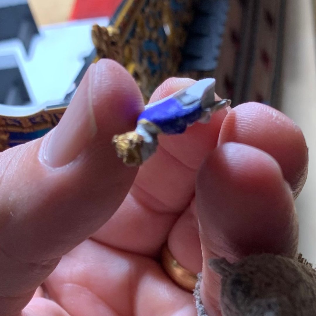
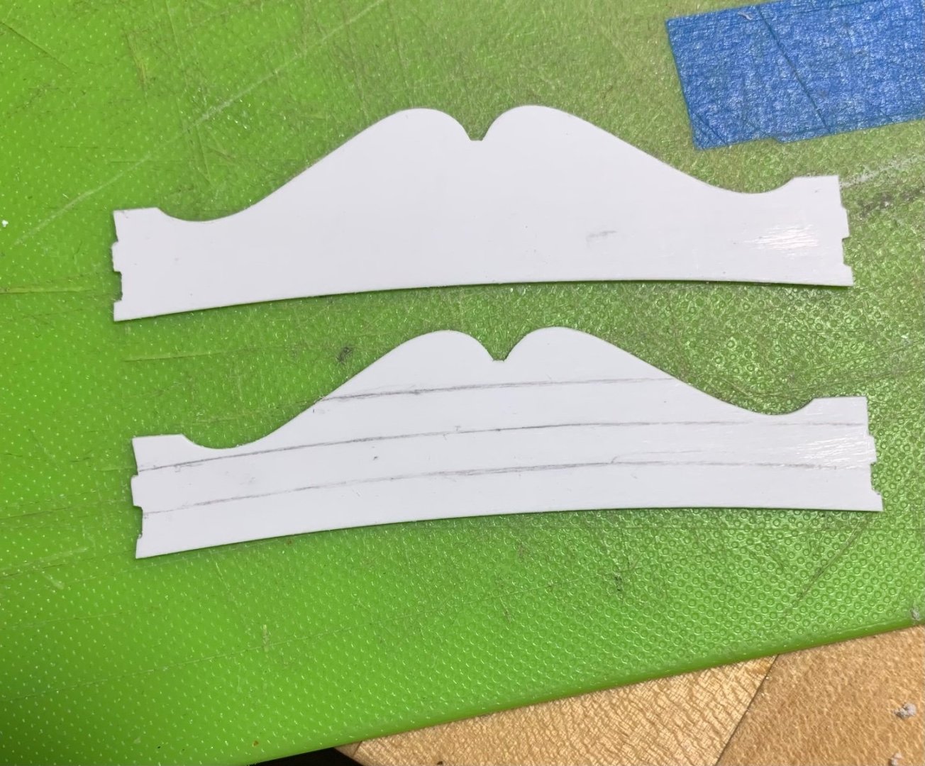
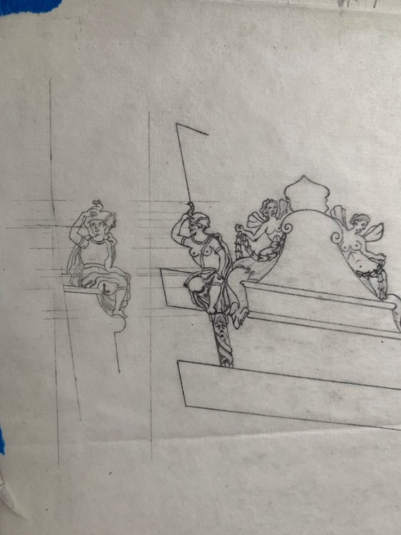
It has been a minute, and I still haven’t gotten to all of my paint corrections, or the glamour shots, but I have been taking the necessary time to as nearly as I can, perfect the crowning of the stern. Once I had secured the backboard, and installed two pre-painted moulding strips to the outside edges of the backboard, I turned my attention to fitting the side-lantern box mounts. Time and again on this build, despite careful pre-fitting of sub-assemblies, I have been amazed to discover just how much additional tweaking of a part becomes necessary, when it must finally seat next to an adjoining assembly. For these lantern boxes, I had carefully set the quarter pieces (that support the boxes) so that the boxes met the sheer-line. Nevertheless, that was before the aft upper bulwark had been secured to the model - after which, it takes on a more bellied shape. Adding to that complication are the fact that my upper bulwark extensions flare out a bit, also, the aft rake of each upper bulwark piece is slightly different from one side to the other, AND, the transom camber introduces another angle to this compound-geometry soup. I spent quite a lot of time filing-in the required geometry and shimming beneath the starboard lantern box before I was satisfied with the way that these pieces married into the astrological band of carvings on the backboard. I only had to use a little bit of filler at the top of each box, but this was an acceptable outcome as this joint is mostly covered by the legs of horse and camel: Above, you can finally see the degree to which my transom winds out of square. This is really the only vantage point where it jumps out at you. All things considered, it is acceptable to me. The above picture already shows the thickening I added to the backboard, in order to make a reasonable seat for the Europe and Asia carvings. Initially, I was going to double-plank with 1/32” styrene strip to make up this thickness, but I ultimately decided it would be much easier to make a close-fitting card template and transfer that to two layers of styrene sheet: The trick to doing this in layers is recognizing that the top edge of this reverse-curve tafferal must bevel down to follow the sheer. So, first I fit the inner layer, traced the tafferal line and removed waste close to the line, so that it would be easier to gauge where the outer layer needed to end up. Ultimately, that’s how I determine the spacing of my scribed planking layout. I haven’t had to use too much putty on this model, but a little was necessary on the inboard corners of this piece: With that much established, I could do the final fitting of the Europe and Asia carvings. Again, these were initially fitted to the backboard when it was flat and significantly thinner. Despite all of the material I added to the inside face of the backboard, these carvings still extended past the inside surface. It is quite difficult, without resorting to transfer paper, to gauge a good fit when you can’t clearly see the joint line. Rather than add a third styrene shim, I decided to round down the bottom line of each carving: This rounding isn’t a bad thing, as it adds a little shape and dimension to the inner surface of the carving, while leaving a little bit of the ledge visible: The whole objective of all of this was to make the reverse-curve profile of the tafferal apparent on the inboard face of the model, as these carvings would have been scribed to this profile, in actual practice. It is very difficult, however, to make a tafferal cap-rail, at scale, that follows this complicated shape. My solution was to add an in-board half-round moulding that completes the illusion. I love using painter’s tape to transfer exact shapes: Above, I found it much easier to shape the top half of the half-round while the moulding was still part of the sheet. Obviously, the thing becomes very flimsy, when you cut out the bottom profile. I decided to leave a slight step, and I am toying with the idea of picking-out this moulding in yellow ocher, just to emphasize the detail. Opinions are certainly welcome on this small detail. In the end, though, I may just paint it flat black like the rest of the top-cap: Next, I secured Europe and Asia. For a little extra bond insurance, I decided to experiment with an idea. I used a #11 blade to scrape thin shavings of styrene: After a liberal application of liquid plastic cement to the bottom of the carving, I bedded a thin layer of shavings over the glue. Another application of cement turns those shavings into plastic goo. I got a little bit of squeeze-out, which won’t be difficult to clean, but I am satisfied that I have a strong bond, here: All of this fiddling and filing makes a mess of the paint-work, and the model is full of plastic dust, at the moment, but here are a few perspective shots: With those carvings in place, the model just barely still fits inside the folding halves of its build-box - less than a 1/16” to spare! I’ll make a small relief in the box leaves, as insurance against catching the nose of these carvings. The other thing I managed to establish is the stern perspective of the Africa carving: Between a pair of vertical parallel lines, I transferred elevations of key reference features from the sheer view. I used a steel ruler much the same way that you would on a full-size drafting table; I simply aligned the top and bottom hash marks for 1” with the left vertical margin, to ensure a square transfer of points. Undoubtedly, there is some margin of error, here, so my primary reference will be the stern view, as that is what determines how the figure seats and fits in relation to the quarter piece. Any discrepancies in the sheer view will be reconciled to the stern view. Later, I’ll get to sheer and stern elevations for the port side figure of the Americas. This will be trickier, as I have no original Berain sheer drawing to refer to. In that instance, I suppose I will start by drawing the stern view and transfer points for the sheer view. Well, that has all been quite a mouthful! Thank you all for looking in and sticking around. I’m gearing-up for another busy school year of coaching youth sports and ferrying kids all over creation. I hope to continue making reasonable progress on the ship, as we go. All the best, Marc


- 2,444 replies
-
- 17
-
-

-
- heller
- soleil royal
- (and 9 more)
-
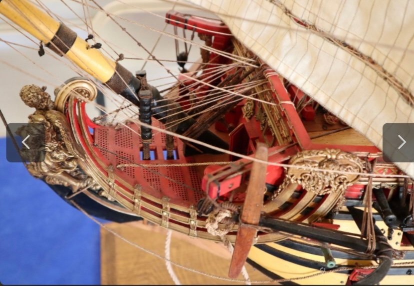
The case is appropriately austere, so that the model can really shine. It has been a real pleasure watching this beauty take shape. I’ve said so before, but one of my favorite features of this model is your particular treatment of the stylized cut-aways; it is unique to you, and really shows the interior to great advantage. Congratulations on the excellence of your achievement! What might you have in mind for your next project?
- 589 replies
-
- 4
-
-
- le gros ventre
- cargo
- (and 1 more)
-
That is some brilliant textiles management, Dan! Is Lt. Pasco nobility though inter-marriage?
-
Frank, all of your extra care and attention to detail has really elevated this model far beyond the kit it started out as. Brilliant work!
- 510 replies
-
- 1
-
-
- reale de france
- corel
- (and 1 more)
-
Thank you, Eric! I thought I might get in some ship-time tonight, but getting back in the swing of life after vacation took precedence, unfortunately. I appreciate the kind words, though.
- 2,444 replies
-
- 3
-
-
- heller
- soleil royal
- (and 9 more)
-
Much better, and yes, I agree with Michael. Good recovery, Bill.
-
I’m sorry to agree, but that is the case. Perhaps you can fish them through the shrouds up at the masthead, with a sewing needle to open a space.
-
I continue to be amazed by your care and craft, Mark. The work is so clean!
-
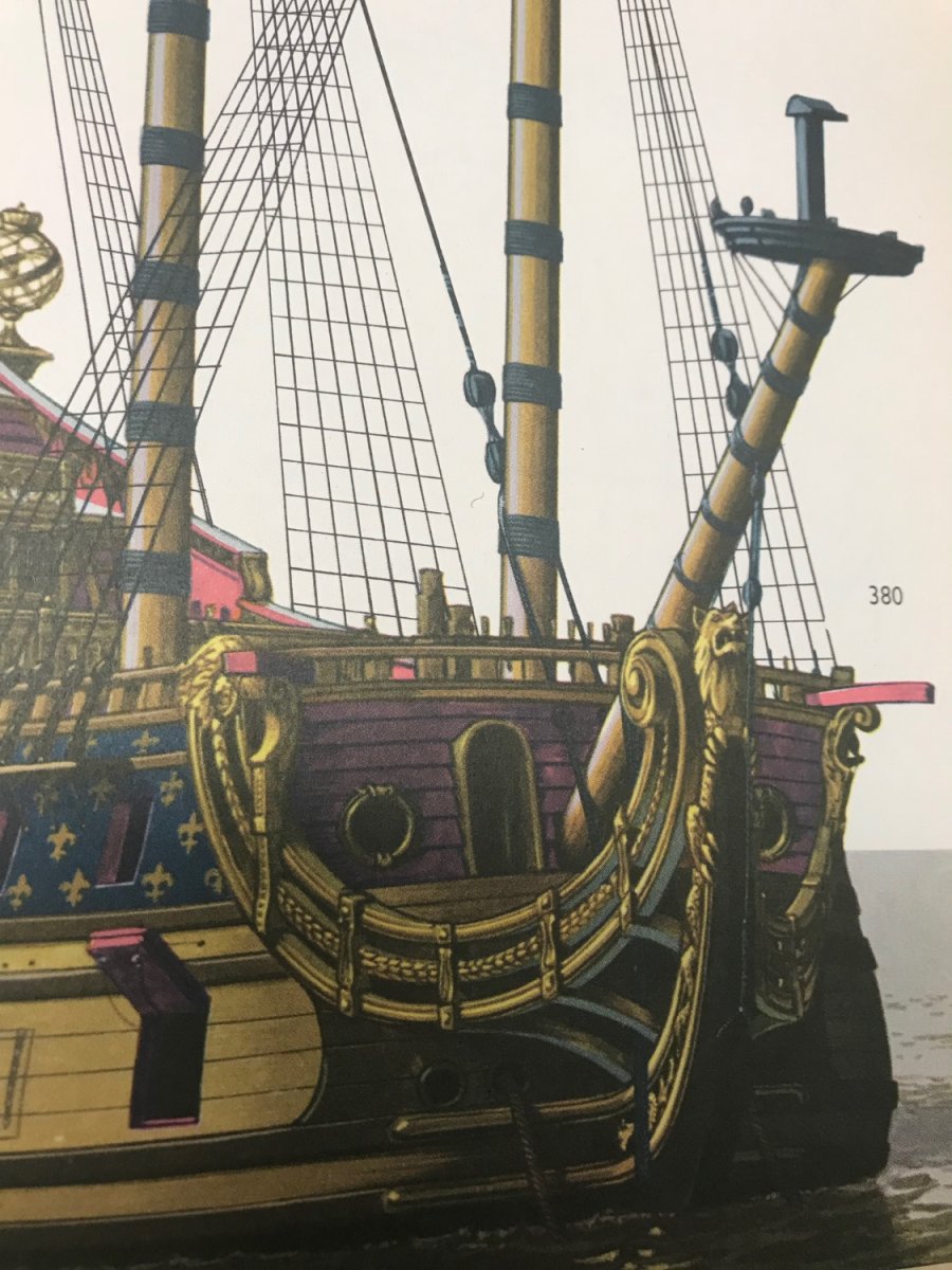
It’s not perfectly clear, but here is Frolich’s L’Ambiteaux for reference:


- 1,503 replies
-
- 1
-
-
- Le Soleil Royal
- Heller
- (and 1 more)
-
Objectively speaking, your rigging work is brilliant, but especially more-so considering the scale. It is always a pleasure to stop by.
-
Does Mile make his own line, or does he source it from someone else? If so, from whom? The line looks very good.
- 86 replies
-
- 1
-
-
- royal caroline
- yacht
- (and 1 more)
-
I’m just catching up, Kevin, and I have to say that you are making a superlative job of this build. Testament to that fact is that Mrs. Kevin is happy to lend a hand at the shipyard. It all looks really great! I must also pay my humble respects to Chris for designing such a great model!
-
Dad is good today - we had a nice birthday lunch!
-
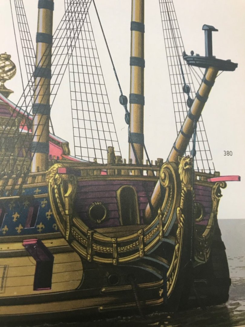
Here are a few pics that might be useful to you bill. The Louis Quinz model: Lemineur’s St Philippe: Bjorn Landstrom:
- 1,503 replies
-
- 1
-
-
- Le Soleil Royal
- Heller
- (and 1 more)
-
A little chocka-block. We were delayed getting out to Hampton Bays by a day, and I was only there for a day and a half. Today, my sister and I will take our Dad out for his 89th birthday with friends. I’ll work a couple of days and then head back out to the Hamptons for a couple more days. Ironically, and in spite of the heatwave, I love the sauna and hot-tub, so I make full use of them while I’m there. Also, my son has been bit by the basketball bug, so we spend a fair amount of time at the courts together. Shooting a basketball has always been one of the single-most relaxing pass-times for me. Tonight, when I get home, I’ll spend some time on the ship. Maybe get my backboard glued in, and other parts prepped and painted. I’ll have some more consistent time off, the second week of August, so that will be nice. Thanks for asking!
-
You and Mike do some of the cleanest plank work on the net.
-
She’s a big girl!
-
Exposed framing is just one of the things you do that I love so much! The effect is dynamite on Constitution, and equally impressive here.
-
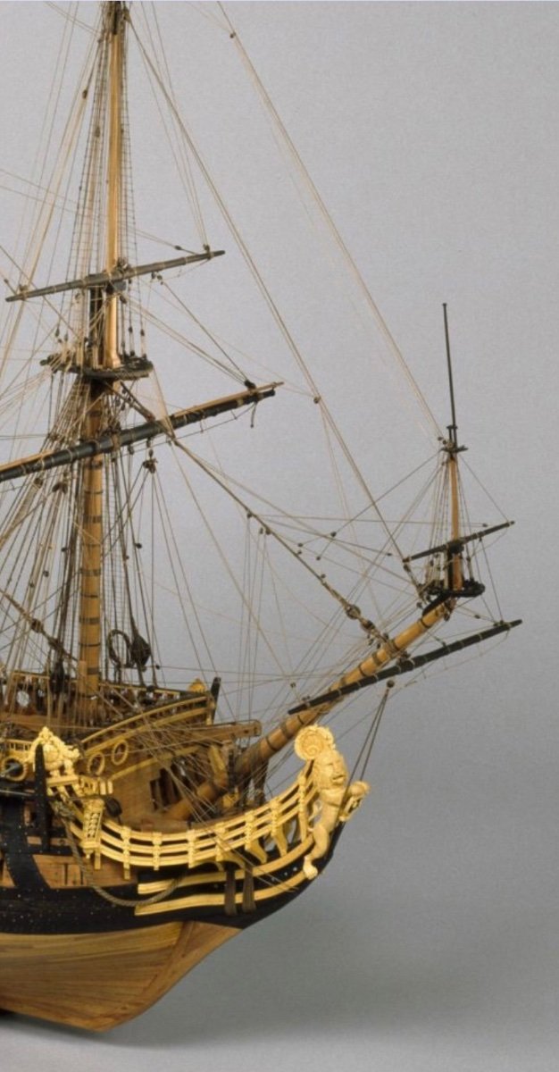
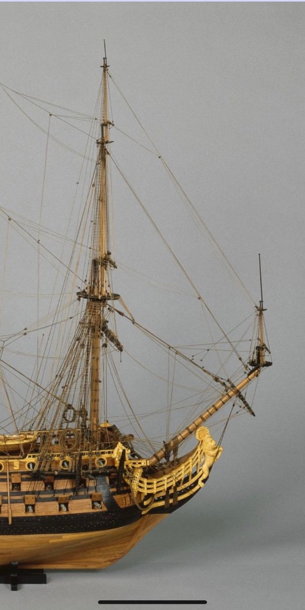
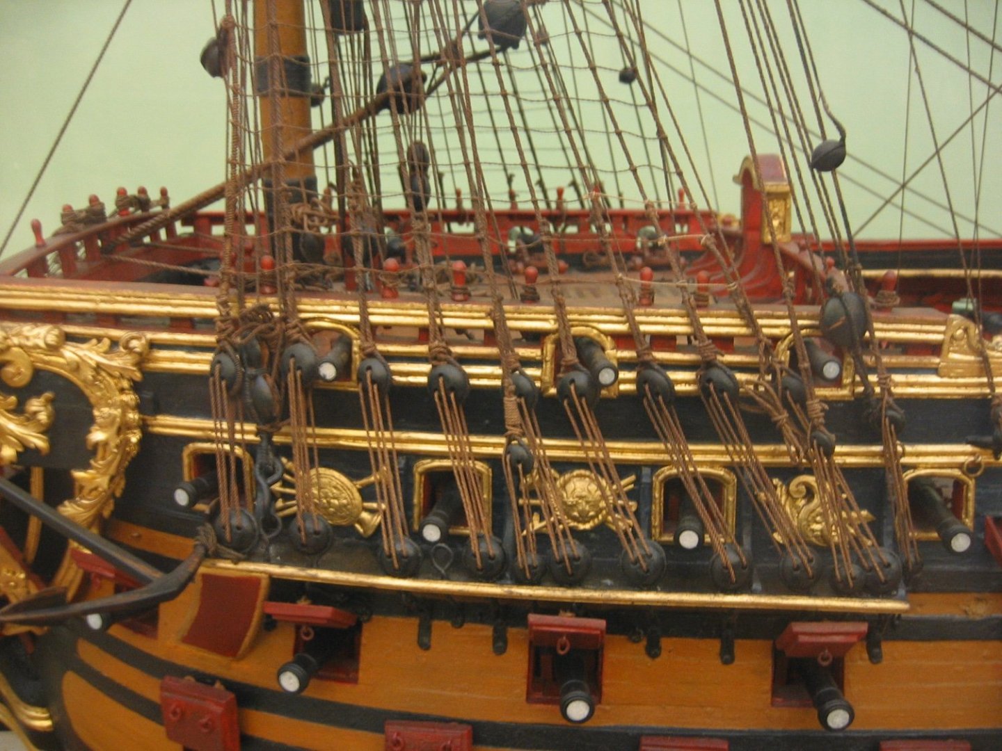
To answer that question, Bill, I would reference builds by some of the more experienced builders to see how they sequence the rigging. Because it is of the period and very present in my mind, here is an extraordinary model of the HMS Sussex: Of course, there is also Marsalv’s Gros Ventre and Archjofo’s La Creole - two of the most exactingly rigged models on the forum, IMO.
- 1,503 replies
-
- 1
-
-
- Le Soleil Royal
- Heller
- (and 1 more)
-
That is an approach that I may be able to adapt Bill. Because it is difficult to find cloth that looks good at this scale, I was planning to make my sails from Modelspan tissue - the stuff airplane modelers cover their fuselages with. In that scenario, you allow the sail area to hang down through a cut opening, and then you wet the material with your thinned glue medium. It produces nicely billowing sails. What I want is a little more extreme, though, so maybe I can adapt your technique and carve the billowing shape out of something soft, like a block of balsa, and then glass the surface of my form with something that the glue medium won’t stick to - maybe epoxy? Back in the pattern shop of Steinway, we used to use this phenolic resin-coated plywood for jig and fixture forms because glue didn’t stick to it. Maybe that kind if resin can be purchased in liquid form somewhere. I would also glue-in thin-gauge wire around the perimeter, to be concealed by the bolt ropes. Thanks for the suggestion Bill, I’ve been grappling with how to approach that problem for some time. If I can pull it off, it will look amazing! Thank you all for the vacation well-wishes. I am looking forward to some time away from NYC.
- 2,444 replies
-
- 4
-
-
- heller
- soleil royal
- (and 9 more)
-
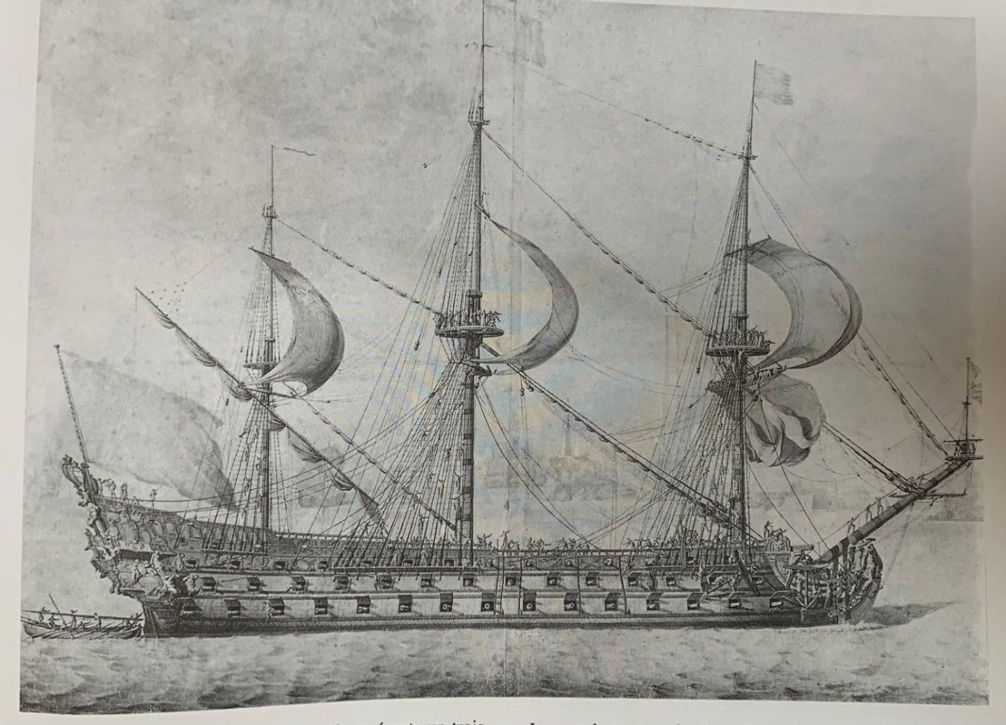
Fully rigged and following the example of unfurling sails shown below: It is tempting to stop at the lower mast sections, and show the ship as laid-up in ordinary, but the overall impression of a fully masted ship, underway, is too irresistible for laziness to intervene. I’m not quite sure how I will achieve such dramatically billowing topsails, but that should be a fun stage of the build. It will all be done at some point before I retire!
- 2,444 replies
-
- 9
-
-
- heller
- soleil royal
- (and 9 more)