BANYAN
-
Posts
5,964 -
Joined
-
Last visited
Content Type
Profiles
Forums
Gallery
Events
Everything posted by BANYAN
-
 You have transformed the model into an educational and interesting asset for the museum Dan; a very nice job indeed on your repairs and detailing. cheers Pat
- 287 replies
-
- 5
-

-
- michelangelo
- ocean liner
- (and 1 more)
-
HMCSS Victoria 1855 by BANYAN - 1:72
BANYAN replied to BANYAN's topic in - Build logs for subjects built 1851 - 1900
Thanks for looking in and kind remarks John -appreciated! Lin mentioned you may be down soon, will have to try and catch up. cheers Pat- 1,021 replies
-
- 2
-
-
- gun dispatch vessel
- victoria
- (and 2 more)
-
HMCSS Victoria 1855 by BANYAN - 1:72
BANYAN replied to BANYAN's topic in - Build logs for subjects built 1851 - 1900
Thanks Carl. That's the sceptre which is made from a small length of brass wire with a knob of sculpting material - it's permanent cheers Pat- 1,021 replies
-
- 3
-
-
- gun dispatch vessel
- victoria
- (and 2 more)
-
HMCSS Victoria 1855 by BANYAN - 1:72
BANYAN replied to BANYAN's topic in - Build logs for subjects built 1851 - 1900
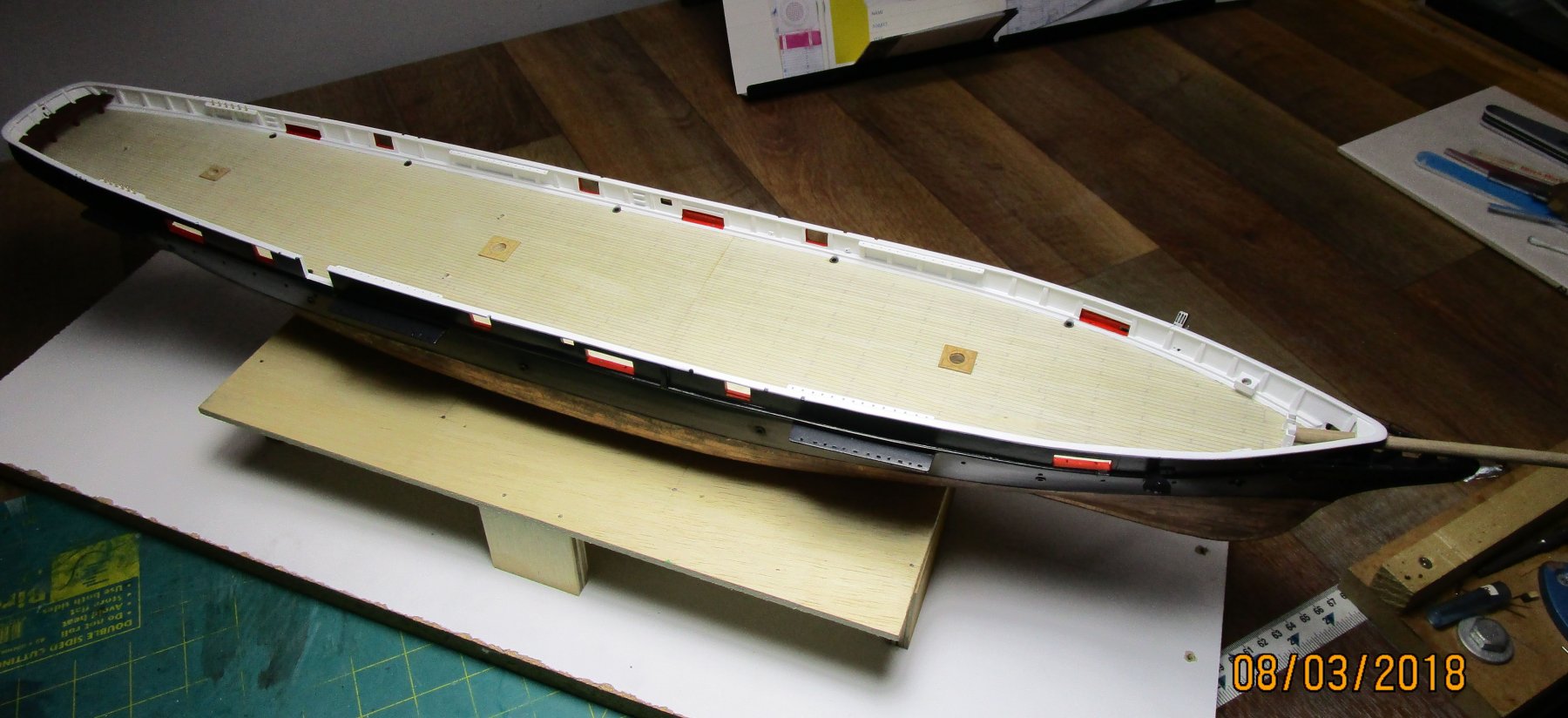
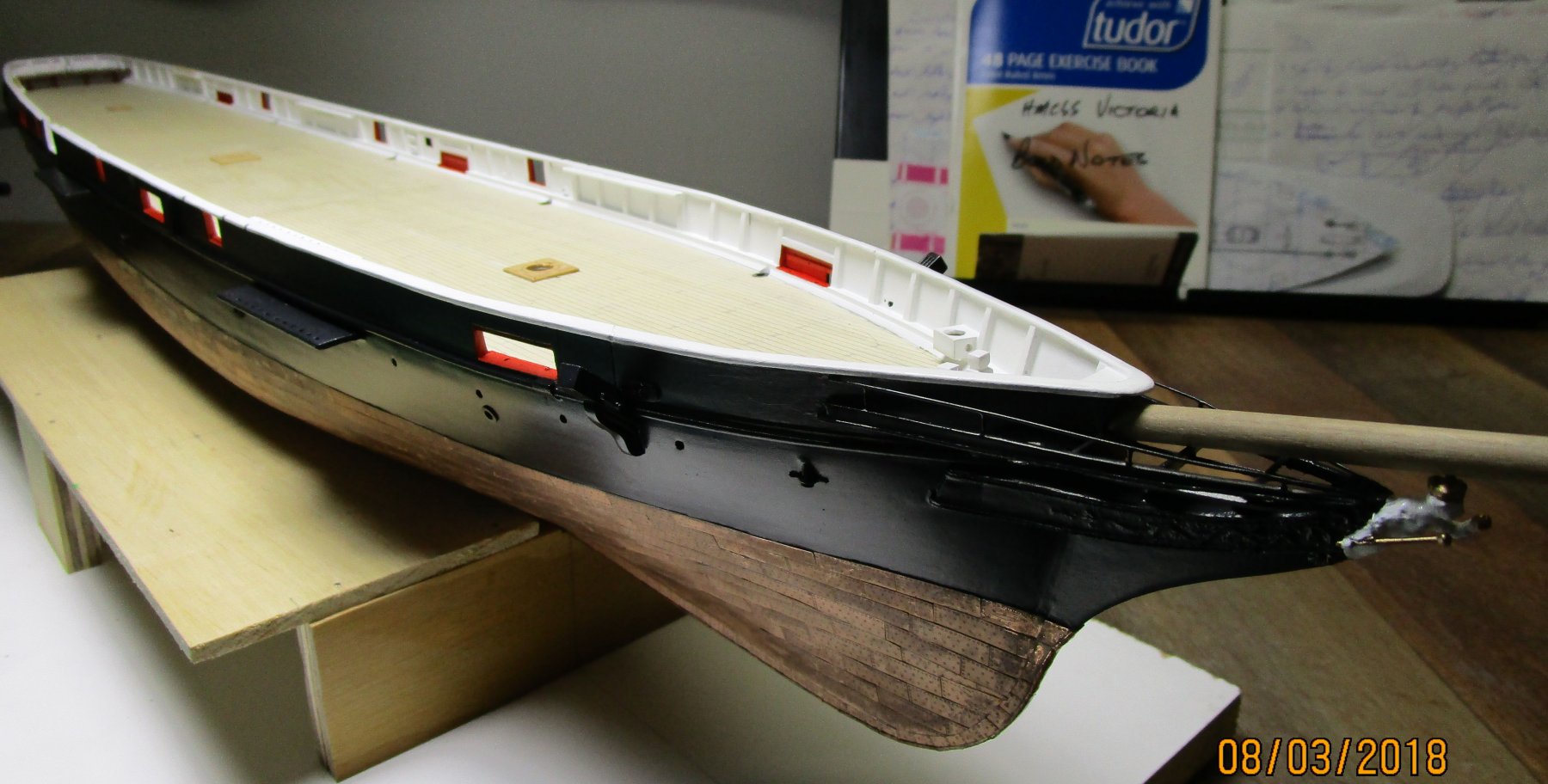
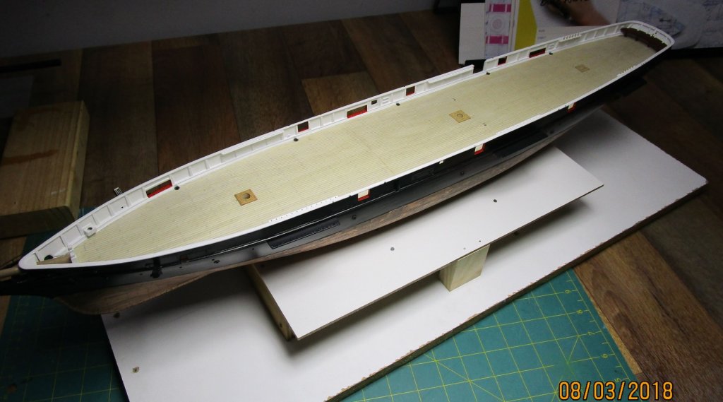
Hi folks, a few more progress pics showing the redone paintwork (hull) - still some touching up needed but it is getting there. Note the 'vermillion' ports (colour as per contract). i have portrayed her with bucklers in place on one side, and open on the other. The bucklers will be secured with a batten across the towing timbers once I have placed them (very soon) using a threaded rod and wing nut system. The next jobs are to add all the detail to the bulwarks which will include, ring bolts for gun tackles and breeching ropes, cleats for securing lines, iron garlands for ready use shoot, lead linesman's platform etc. As usual, all comments, suggestion for improvement etc are most welcomed. cheers Pat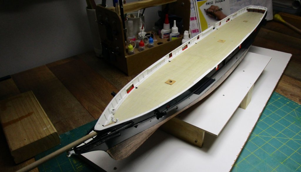


- 1,021 replies
-
- 16
-
-
- gun dispatch vessel
- victoria
- (and 2 more)
-
Hi Greg; sorry for being AWOL for this build - hope there is some prime viewing room left Great subject and you have made some really good progress; that hull looks very true with the primer. As to Vallejo; couldn't agree more - I tossed mine. cheers Pat
-
Very clever Tecko; a little humour to keep the viewers attention is a great idea. This will be a very interesting diorama. cheers Pat
-
Looking very good Danny, pity about the red print mismatch, but the model overall is very consistent. cheers Pat
-
Stunning work Jason; very nicely detailed with clean sharp finishes. I have to agree with your choice on the 'gingerbread', the Georgian detail looks the part - she is looking very good indeed mate. cheers Pat
-
Thay have that routine worked out very well. It is amazing what the old generation could do without the power tools these lads are using. That is not to take away from their skills; they certainly work fast and well. cheers Pat
-
Norden is looking very much the working boat now Denis - nice job. cheers Pat
- 378 replies
-
- 5
-
-
- t78 norden
- billing boats
- (and 1 more)
-
I reckon these will turn out quite well knowing you Mark; a few done each day will soon add up without too many headaches. get those yarddogs busy then cheers Pat
-
Very nicely executed detail Danny. This model is so well done that at first glance you would never know it is card. cheers Pat
-
Your joinery is absolutely first class Amalio. cheers Pat
-
A very informative update Ed; thanks once again for showing us some of your techniques - the copper wire wrapped to simulate the shackles is very effective! Those yards and rigging details are exemplary and show what can be done with a little care and attention to detail. cheers Pat
- 3,618 replies
-
- 3
-
-
- young america
- clipper
- (and 1 more)
-
That's a brilliant painting Jim - really catches the fishing village atmosphere cheers Pat
-
ancre Chebece 1750 by Jeronimo - FINISHED
BANYAN replied to Jeronimo's topic in - Build logs for subjects built 1501 - 1750
Stunning! I don't think I could try to do justice with words cheers Pat -
Busy boy indeed Danny; seems you are ready to move onto the next kit Nice work on all that detail; it will look good in-situ. cheers Pat
-
Hi Techo, just found your log and what a great subject to see and learn about. Enjoyed getting up to date and look forward to your future contributions. cheers Pat
-
Beautifully crafted ironwork Ed; working with copper has become my 'norm' now as well - many thanks for pointing me in the 'right' direction cheers Pat
- 3,618 replies
-
- 3
-
-
- young america
- clipper
- (and 1 more)
-
Poor Man's Lathe disasters
BANYAN replied to stevenmh's topic in Modeling tools and Workshop Equipment
That is a pretty good setup Carl; I am assuming the plated slot is to allow smooth sliding if a steady-rest? Is that a live-centre on the tail end? cheers Pat -
Noted Riverboat Modeler Glenn Hensley has passed away
BANYAN replied to kurtvd19's topic in Nautical/Naval History
Thanks for letting us know - another sad loss to the maritime, and in particular the ship modelling world. Pat -
Very nice job on the parrels Dave; the fun part is fitting them The printed versions look great with a uniform size and shape, and they look just like real wood. I did find some elongated beads but noting that looked right to provide the small oversize relative to the parrels themselves; your beads look about right at 1:60. I fitting the parrels I cheated a little. At one end I left a loop which went over the yard end and brought to the centre which simply left one end (two tails) to wrap around the yard. I passed these back and forth several times within the valley and then only had to tie off one end. Made it a bit easier but still took a bit of 'practice' to do in-situ. cheers Pat