BANYAN
-
Posts
5,964 -
Joined
-
Last visited
Content Type
Profiles
Forums
Gallery
Events
Everything posted by BANYAN
-
 Hi Tom, Chuck has pretty much answered as much as I could and based on his greater experience. My comments are based on assumptions as I have not actually derived how Jim's spools spin. My assumption is that when you stop the winding by tension on the hand wheel, this causes the spools to engage. As Jim states you need to use RH laid stock thread and load/configure the spools/bobbins in a set way, this implies that the spools are spinning the rope from threads against the lay of the thread which is now pre-tensioned. What I meant in my statement is that I allow the basic/initial motion of the winding action to take affect to pretension the threads before I start spinning the rope. My current 'work flow' is to start the machine at the desired speed and hold the take-up spool so that the machine pretensions the threads and starts to wind the slack to the point I feel resistance on the wound threads pulling on the take-up spool. At that point I tension the hand wheel and hold it to engage the spools. This seems to create a reasonable rope as you have the counter tensions of the stock thread and the made-up scale rope working against each other to keep the rope 'tight' or in suspension/balanced. I hope this clarifies my comment? cheers Pat
 -
Chuck is spot on with the Byrnes ropewalk (and I therefore assume the Russian version as well). You can pre-wind BUT the speed of the machine is the most important. As Jim has a variable speed controller (no scale) this has to be pure judgement. I learned the hard way to first spin the machine for a short while (no tension on the hand wheel) until the strands have wound to a 'certain' degree - this is a judgement thing also based on the number of strands and size of the stock thread. When it looks about right apply tension to the hand wheel to causer the spools to wind the rope strands and lay the rope up. I also harden the same way as Chuck by stretching as it comes off the spool but as I use a cotton-polyester thread it also retains some elasticity so I hang lengths of scale rope with a swivel weight at each end over night to try and remove all stretch. The other factor I have found with Jims machine is to stay SLOW! Jim suggests you can speed it up as you get practice / become more experienced; however, I find that speeding it up too much requires different pre-tensioning/winding of the threads. I have had best results keeping the machine relatively slow - the best I could describe is that I am winding the take-up spool at about one turn every two seconds (ish). I hope that helps. Please note I am still only making LH lay rope and have yet to experiment with RH lay, but as with Chuck's rope, I can cut it with no parting of the strands at all. cheers Pat
-
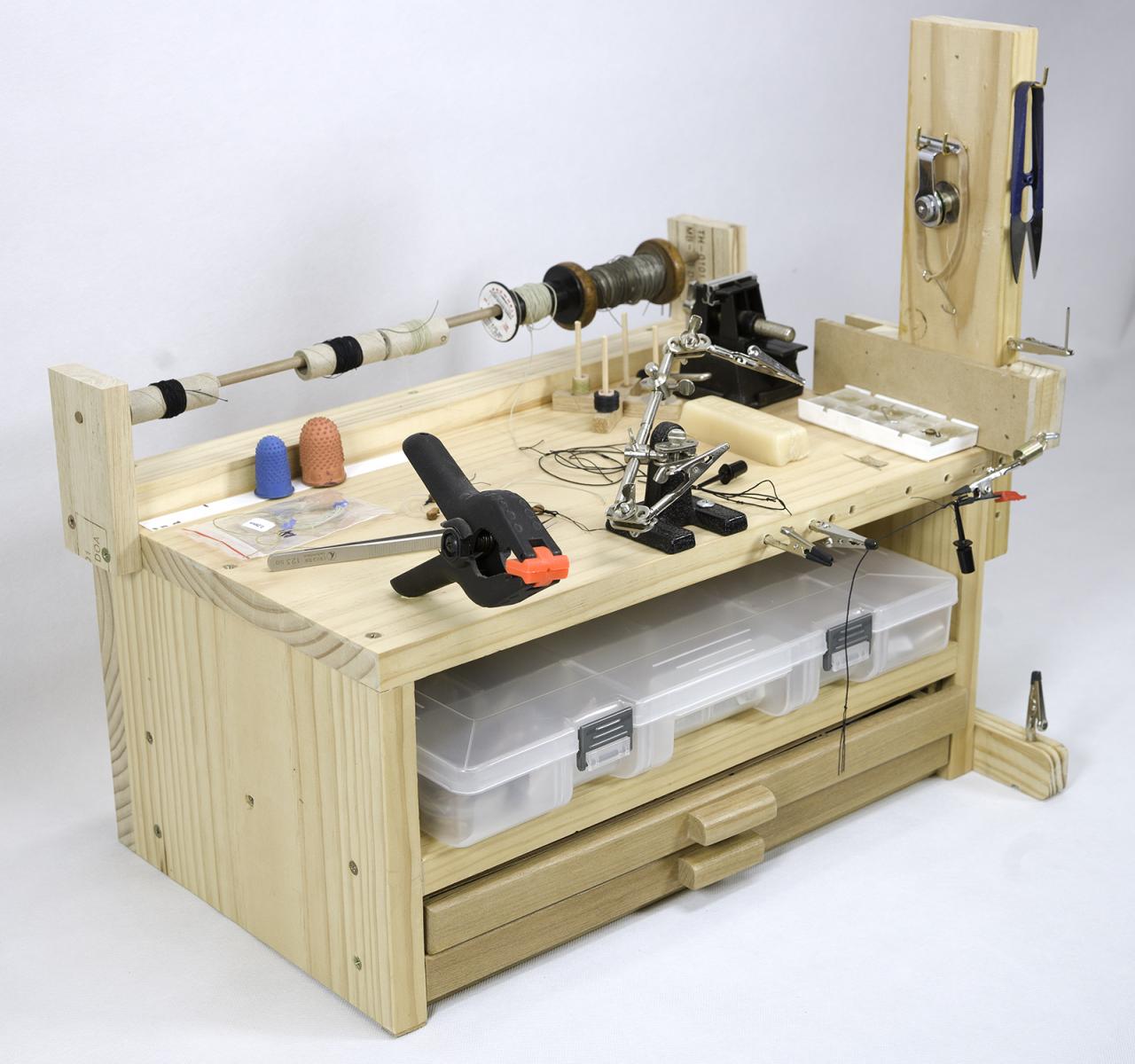
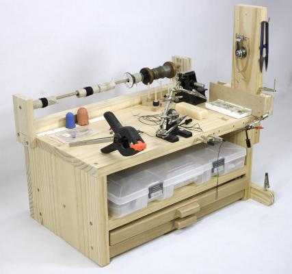
Thanks John, Alister, Mike, Greg, Brian and Slog for looking in and the encouragement. Once I get these shrouds sorted I should be able to proceed at a better pace. John, yeah, this was a surprise as these were silver soldered, The served shrouds tend to not stay straight and need a little pressure to keep a neat appearance - perhaps I am serving them too tightly. Greg, the shrouds are giving me enough grief (getting them to the right length as the serving on the foreleg of the front pairs proves to stiffen them, and then when the shrouds are 'pinched' together near the tops, it shortens them again (no planning/foresight by me on this so a big learning curve) - oh well live and learn - and... thanks (I think)) for the warning on the ratlin' Slog, Mike and Greg, the basic idea for this rigging station is one adapted from Hubert Sicard (Wooden Ship Modelling for Dummies); he calls it his 'rigging crab' due to the multiple appendages. I have made all bar the small drawers in the base (which dictated the width and depth of the station) which I obtained from an artists supplier (used to store their brushes etc) and are reasonably cheap. The upright can be adjusted up and down depending on what length you need for the job at hand. I still need to add an adjustment device on the horizontal that holds the alligator clips to give me just a little more room behind the rope when serving or whipping etc. The only other planned addition is a jig to hold the yardarms when rigging footropes but I haven't worked that out fully yet. cheers Pat
- 517 replies
-
- 3
-

-
- Endeavour
- Artesania Latina
- (and 1 more)
-
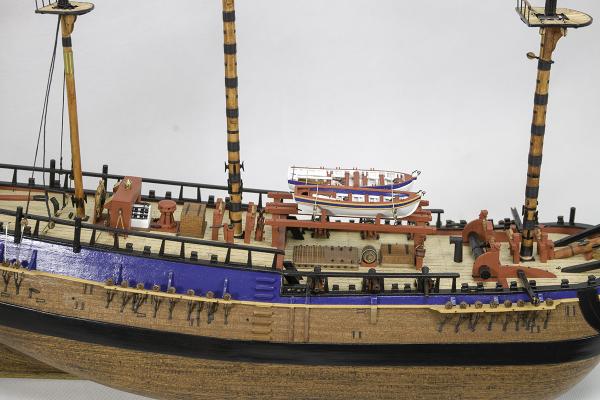
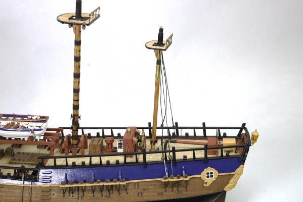
Hi again folks, a small update to the build. I have been busy preparing some details for the rigging. The ropewalk is now up and running along with my server and I have manage to produce a couple of shrouds etc with a decent serving on the fore shroud of the front pair (mizzen). Not happy with the length of these so I will probably redo them. I also have to repair a chain plate that came adrift under pressure but unsure whether to attempt this on the model or remove the channel edge strip (afraid I may damage the whole channel though in doing so) and then replace the whole chain with deadeye after repair. One of the photos shows my rigging station which is being modified as I find better ways to setup various rigging activities. cheers Pat

- 517 replies
-
- 5
-
-
- Endeavour
- Artesania Latina
- (and 1 more)
-
Hi Jim and Ulisis, firstly I hope all had a great Christmas. Jim, thanks for looking in over your break - much appreciate the feedback to Ulisis as it helps me isolate my issues also. Ulisis, the looks of your rope is very similar to this the problems I experienced and described when I had a loose inner belt. Mine is starting to go that way again and the 'o-ring' on mine is relatively new (replacement). Jim, mine is still creating rope that I can use but I have to select parts of it and stretch it (a lot) after making to remove the bumps Ulisis reports. To my non-mechanical mind, it appears to be the belts slipping again as when looking closely at the rope, it seems to be one strand that stands proud of the others (as if not the same amount of tension is applied. I have checked and isolated spool winding as I have a rig set up now to supply the right amount of tension evenly to all spools as they are wound. Would a leather belt work in lieu of an o-ring on the inner pulleys or do you need a certain amount of flexibility so as not to overstress the mechanism? cheers Pat
-
Very nice Slog! keep jumpin about mate, keeps the reader more interested also cheers Pat
-
No problem at all. This is a well machined ropewalk and when the belts are tight makes very nice LH rope (still experimenting on RH) using a very small footprint - its a pity these belt issues are arising (well for me anyway). I don't want to pull it apart to measure the belts at the moment as I am trying to make the LH (cable) laid shrouds and stays at the moment. I have tired with shroud laid (fourth rope through body from the spool behind) but the lay just not sit very well - early days though and could be partly related to the loose belt. I would put up pictures but it is hard to show the detail of the issue. In appearance my rope looks like one of the strands sits slightly proud of the other two which is what makes it look lumpy; then every so often a small kink n one of the strands appears (like a small crows foot, I am now making smaller lengths (about 1.5 to 2 m max) which when I stretch to set it and take the elasticity out, settles the lay and it is acceptable to work with. cheers Pat
-
I have got mine up and running now (finger problems - I was not holding the tension wheel at the right time) - I wish there was a way to secure this - tried the rubber band trick you mentioned but it kept slipping - will need to try a better/stronger rubber band. You really need one hand free and without a motorised take-up spool it just makes it too hard to control speed etc. I am now making rope but having the same issue as you mention, it appears lumpy. The made-up scale rope does improve if I stretch it, but shouldn't have to I also think the belt is a bit loose; this is the same problem I had in the first instance when I had to return it to Jim for checking and it proved to be the belt being loose - made beautiful rope straight up after he returned it, but now. I really do think the belts are suspect as my main drive belt is severely cracked and looked perished, and my new belt on the spool pulleys is already starting to show some perishing (and I have had it stored away under cover). The new belt seems quite loose again, I can push it all the way back to the hub centre with very little fingertip pressure. I am waiting for Jim to return and see if he can provide the appropriate data for the belts and I think I am going to try those 'green' (felt or leather?) belts that drive the small mills and lathes used by Jewellers. They seem to be much better quality. These rubber ones are hopeless!
-
Thanks for the pointers Alistair, they look a good read. I'll keep my eye open for some of these cheers Pat
-
Thanks Jud, appreciate the feed back and I think is probably the only real way to get sufficient tension. Having rubber belts doesn't help; I'll see what Jim comes up with. This shouldn't happen and I hope he can come up with a solution. cheers Pat
-
Is anyone else having problems with thier ropewalk? I have not used mine for about 6 months and went to use it recently and it appears the belts have gone again!!!!!!! nothing I do (and I have tried everything) makes the ropes set. As soon as I stop the machine it starts to unwind. By the time I have taken it off the winding spool it has already unravelled. it appears that the belt that drives the bobbins does not have enough tension to keep them spinning! I am so frustrated as this is the second belt now - if this is the problem it seems they justy stretch way too easily!!!! cheers Pat
-
Thanks for the update Wefalk, the wait was worth it - WOW. Very nice work mate, and as Druxey has commented that rigging is supurb for such a small scale you are workig at. I hope all is well with ealth after your short hospital stay! cheers Pat
-
Danny that is great work on the timberheads; I wasn't aware the angle of the 'head' also sloped to conform with the caprail etc - live and learn - thnanks for the education along the way. cheers Pat
-
Chamfer a plank
BANYAN replied to Thom's topic in Planking Techniques's Click Here for Topics dedicated to planking!!!!
Hi folks, in my limited experience, I have found that if you are 'spiling' then each plank pair will have a slightly different profile (mostly) so marking the line then cutting, shaving and/or sanding back to the marked line on invidual planks is the best approach. However, for some models when planking in bands where you may have (say) 5 planks that taper evenly going forward that you may be able to shape each to very much the same profile. For this I used the old Mantua Strip Clamp (see piccy -it has a metal vice surface to sand to and uses cam locks to apply pressure) to be very handy; but, it may require repositioning the planks a few times to get the right profile. You could make a home-made version of this. Basically, using whatever method you prefer to determine the required profile, transfer this to a single plank. Stack a few planks (I work on up to six at times) in the clamp ensuring they are truely aligned and with the marked plank on the outer side from which you will be working -I then clamp the whole assembly in a bench vice to stop it moving, but you could use a bench stop, anti-slip mat or the like. Now use blades, planes and/or sanding to reduce the planks to the the profile line. If it is a complex curve/shape, as I said earlier you may have to reposition a few times and this is when it is important to ensure the stack of planks do not move (relative to each other). I use a bit of low-tack tape wound tightly (only once) around the stack in two areas where there is little or no clamp pressure to assist. For best results it is still best to slightly bevel the edge of each plank in the appropriate plane/alignment to get a good fit especially on vertical curves/rounds in the hull. i hope this helps? cheers Pat -
Thanks Wayne - back to the (virtual) drawing board and more practice
-
Hi all, and many thanks for the valuable feedback. Grant, thanks to the pointer and exactly the sort of thng I was trying to achieve with lines but not using the correct command (3 point Shrink/Expand). Many thanks for that! Wayne, thanks for looking in. I am ever so glad you haven't removed it as it is still a very useful tutorial. I will heed your advice to treat it as a guide rather than gospel as, among other things, some ways of doing things may be version specific. I have another image to import tonight so I will give your method (as advised to Greg) a shot. I am only doing deck arrangements and a side profile (as drawings) so the issues with waterlines and stations is not a great concern in this little effort thankfully. Thanks on the idea for keeping the lines to the fore also. As you say rescaling the AP, FP and Keel is a 'good thing', it's the alignment lines I want to keep as are. We spent a bit of time in Photoshop adjusting the side profile photo as it was actually slightly stbd bow offset (towards camera) and we needed to adjust for that so we could use the photo to create alignment lines for the positioning of some of the fittings. Wayne while I have your attention (if I may) - another frustration I am dealing with is TCs penchant for returning to the last object used for a particular drawing tool. For example, if I select polygon line tool, I return to the model space and if I am not careful to check (more often tha not ) TC draws the new object on the layer this tool was last used, even if it is locked - is there a way (preference setting I have missed?) for stopping this that you have found? HSM - may thanks. I am using TC 20 and I am finding that importing very large images is not a problem and I have four embedded so far - waterlines for the actual ship, deck plan for Arrow Class, deck plan for Vigilant class and a side profile plate photograph (taken in 1868) - I have a scan of a side-profile lithograph to go. Great tip about cut and paste direct from Graphic programs - thanks. [Edit: Apologies to Grant] cheers Pat
-
Same as with many of the other comments - have a pair (with the intention to use them for planking) but they haven't seen the light of day Tick strips have replaced that idea - Druxey, great idea on the radiating lines; just need to be very careful in producing a set to ensure accuracy? cheers Pat
-
Thanks for the promt response Harvey, helps a lot and I appreciate your feed back. I had hoped Wayne may look in I have set a target to reread his tutorial this weekend. WRT full size loft - Yep! Only way to go as you have suggested. I am also using the trick of the extended lines, but wished to avoid the constant zooming. The other trick I have found is to bring the other layers/objects to the front (viewing) is to click the eyeball off/on for the associated image layer, this brings the the dimension and alignment lines to front again. The benefit is that I have found drawings of some of the ship's equipment/fittings which are drawn to scale which I can import and resize to the real dimensions and then align them before tracing over them (e.g. I know the chain cable was 1.5" diameter, so the drawings of the capstan can be rescaled until the chain is 1.5" and then the capstan should be to actual size also. I wasn't aware of the Scale X/Ypicks, I need to investigate that a bit more - I am assuming this is scaling down / up in factors with 1 = 100%. When you say 'lock' the ratio aspect is that the button / tool for ' keep aspect' or something similar; in the local menu? (in TC 20 anyway). OR, is it like the little lock that locks the field value in the inspector bar? Is that the place this Aspect tool lives also? Anyway, back to the TC forum to investiogate the Scale picks now - thanks. [Edit - Havrvey tried the scale pick boxes and they worked a treat for rescaling concentric odd shaped items such as skylights, not as helpful as for the rescasling of the larger images though] cheers Pat
-
Hi, I am a relative newbie to CAD (using TurboCAD 20 Deluxe) and believe I am going about the scaling process the wrong way. Could anyone please advise the best way to scale an imported picture which I intend to use to trace, or take alignment lines from. I am trying to draw the deck arrangements for a ship (one-of -a-kind design) but very similar to the gun despatch vessels of the mid-nineteenth century. I have already imported the deck plans for two of this class as well as a photo (adjusted) which I use to trace and/or align to draw the deck fittings/arrangements. To date my routine has been to create a layer with dimensions (real-world scale) shown. I then import the image, rotate it to get it level and then manually adjust it (takes a lot of fiddly adjustments but eventually I get there) so that the picture fits to the required scale (as drawn on the Dimensions layer - usually the length between verticals with elongated perpendicular ends). This process is difficult as when the object (layer) to be scaled is selected it comes to the fore and hides the underlying dimensions/scale layer. Sending it to the back is not the same as layer management in say Photoshop, as in this case it is the objects that are sent to the back (which can be on the same layer). Is there an easier way? I was hoping to try and draw a line on the imported picture (say between the verticles), lock/merge/group this line with the picture, and then set the line's length via the properties/values for line length hoping this would then scale the grouped photo with it - BUT this does not seem to work (or more likely I am doin git all wrong ). Also, is there anyway in TurboCAD to make layers semi-transparent when working with them so I that can see the image/lines under the selected object while manipulating them? A lot to ask but I have been unable to find anything in the set-up or preference3s etc to do this. I would very much value any ideas or tips from you experienced folks? cheers Pat
-
Very nice work on the planksheers Danny. And - that's not cheating - its being 'creative' or practical cheers Pat
-
Careful Keith, you'll be a tool' aholic before you know it You may even need to sell off some of that supurb sound equipment to buy the tools WRT to developing your skills, you've come a long way but I know what you mean. I look at my Endeavour and just wish I could redo some of the very early work again. But like you, I have accepted it for what it is and I can live with it, and will strive for better in the next build. If you are looking for a smaller project have a look at / maybe consider the Longboat or Cutter kits (from Model Expo) that Chuck designed. Quite a nice project that brings in some interesting build challenges? cheers Pat p.s. Don't be too concerned if not too many people coimment in your log - you probably get a lot more visitors that read the page but don't comment. There are a lot of build logs and I only comment in about 10 myself (not enough time for others but they do deserve looking at - purely time management), but I do realise it is nice to get some acknowledgement for your efforts at times
-
Thanks Greg; on the model then cheers Pat
-
Very nice work on your rigging Greg, she is coming along really nicely. I am due an update (you have shamed me into it ) as I have stepped the lower masts and made a start on the rigging. Did you do your crows-feet while the mast was off or when stepped? Iam trying to decide which is easier cheers Pat
-
She came up very nicely Keith, the woven sail reinforcements look good - glad you put that detail in. I love that little flourish on the display stand with the anchor did that come with the kit or an enhancement you made? cheers Pat