BANYAN
-
Posts
5,573 -
Joined
-
Last visited
Content Type
Profiles
Forums
Gallery
Events
Everything posted by BANYAN
-
 At least you are still making progress Denis; and she is looking grand. WRT the rubber bands, it may also be that fumes, or contact with, the glue accelerated the deterioration of the bands - I replace them quite often because of this. cheers Pat
 -
Hi Dashi, sorry I don't have sufficient knowledge in these things to provide a definitive response for you. However, your research results appear to be fairly categorical in the absence of the supporting evidence used by Marquardt for the AOTS. There may, or may not, have been a good reason for his choices. I would recommend an email to the Replica guys to see what they did and why also;that may assist in resolving your dilemma? I must admit, I simply followed the AOTS. I agree with your assumptions though that these smaller spars were relatively easy to replace with onboard spares with minimal shaping to adapt them for a specific purpose. When used, a suitable blank spar timber replacement could have been sourced in many of the places he visited including NZ. cheers Pat
-
Great work UV, that looks really well done. A complex task broken into smaller projects will get the job done cheers Pat
- 786 replies
-
- 2
-

-
- Royal Louis
- Finished
- (and 1 more)
-
Man that is some lovely work Rob; a joy to see. cheers Pat
- 1,205 replies
-
- 3
-
-
- great republic
- clipper
- (and 1 more)
-
Don't worry, I am sure I would earn the bosun's wrath if he were to look at my belaying (wrong pins, leads etc) There is a booklet that is provided to volunteers on the Endeavour (when sailing) that provides the rigging plan/belaying they use so that they can learn 'the ropes' - that is also very handy if you can get your hands on it. Unfortunately I have passed my copy to another builder. that said though, there are some differences with the replica as may have been the actual belay plan, as is Marquardt's interpretation - but it can't be too far wrong cheers Pat
- 108 replies
-
- 2
-
-
- endeavour
- caldercraft
- (and 1 more)
-
TLAs, FLAs etc (Three Letter Acronyms, Four Letter Acronyms ...) When we went to a particular deployment back in the early 90s, one of the first things handed over by the USN was a book of Acronyms (A4 paper, double sided and over 2 inches thick!) cheers Pat
-
Hi Rod, WRT the AOTS, the info is in the book, you just have to hunt around a bit. The main plans you need are the the Belaying Positions for Running Rigging (page 120) and Running Rigging drawing on page 102. By looking at individual lines etc on the detail drawings (pages in between) and these two you can determine where each of the running rigging lines lead and belay. For example if we take line 19 in detail drawing I1/2 (page 103), the legend informs us it is the Spritsail yard brace (the title of the legend tells us it is for the lower yard). Then if you go to the belaying plan on page 120, and find that line in the tabular listing to get the position number (item 11 in this case) then find that position on the plan and you see that it belays to a belaying pin in the foremast fiferail/crosspiece (third in from the port outer side). Not the best schema but it works, just need to find the appropriate drawings. The main purpose I use page 102 is to help identify the main running lines leads and positions. I photocopied copied the two main drawings and enlarged them considerably to make life easier. The same generally applies for standing rigging (pages 95-100) but here there is no horizant (plan) view but is fairly evident where the lines secured. I hope this helps; just holler if you need further clarification cheers Pat
- 108 replies
-
- 2
-
-
- endeavour
- caldercraft
- (and 1 more)
-
Nice work Patrick, she looks fabulous! Even though we know it is a 'micro' build, it is not until you show her in your 'giant' hand that we can visualize just how small these furnishings (and the model) are. cheers Pat
-
HMCSS Victoria 1855 by BANYAN - 1:72
BANYAN replied to BANYAN's topic in - Build logs for subjects built 1851 - 1900
Thanks Eberhard, your advice is always most helpful. I used the sherline for turning the body of the pump with my duplicator (which needs some refinements for smaller work I found ). I really need to get my jewellers lathe up and running for this finer stuff - I have been lazy (well I could say too busy elsewhere) but I really need to do this sooner rather than later. I purchased some of that green pulley belting you recommended; now to set up the motor and get some decent attachments such as this double roller - excellent idea. cheers Pat- 988 replies
-
- 4
-
-
- gun dispatch vessel
- victoria
- (and 2 more)
-
I am very much enjoying your updates Michael; a great display of masterful modelling. cheers Pat
-
Yep, you better make sure you keep the lady happy otherwise you may find your fine build de-masted cheers Pat
- 1,205 replies
-
- 2
-
-
- great republic
- clipper
- (and 1 more)
-
HMCSS Victoria 1855 by BANYAN - 1:72
BANYAN replied to BANYAN's topic in - Build logs for subjects built 1851 - 1900
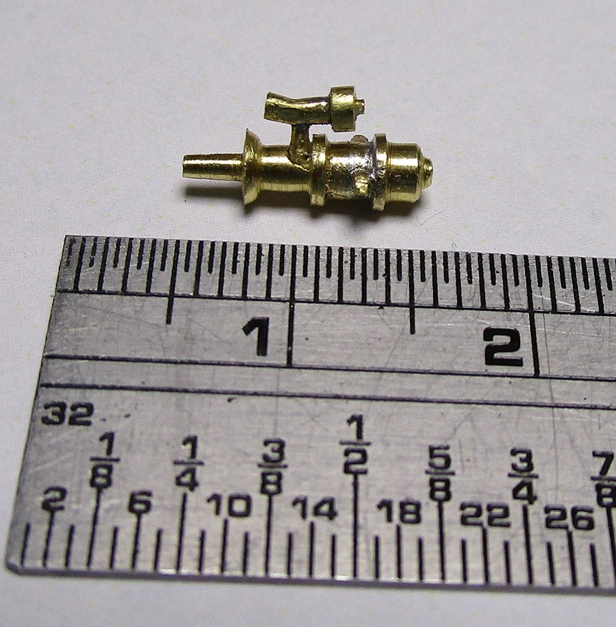
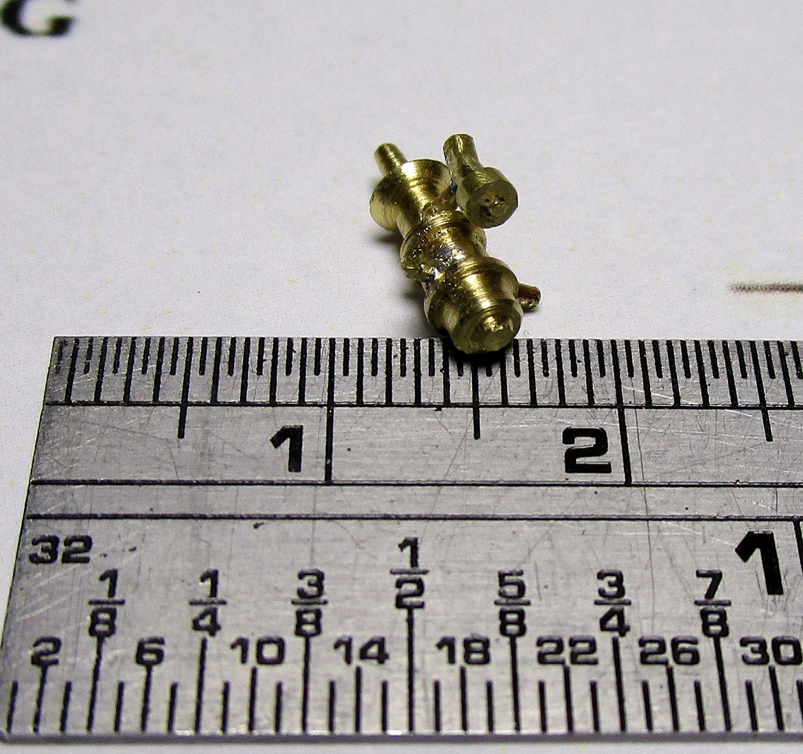
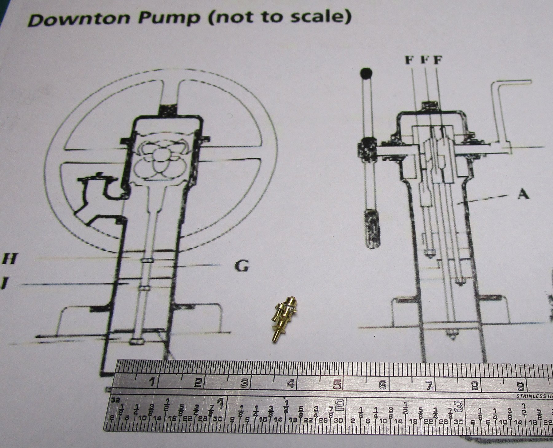
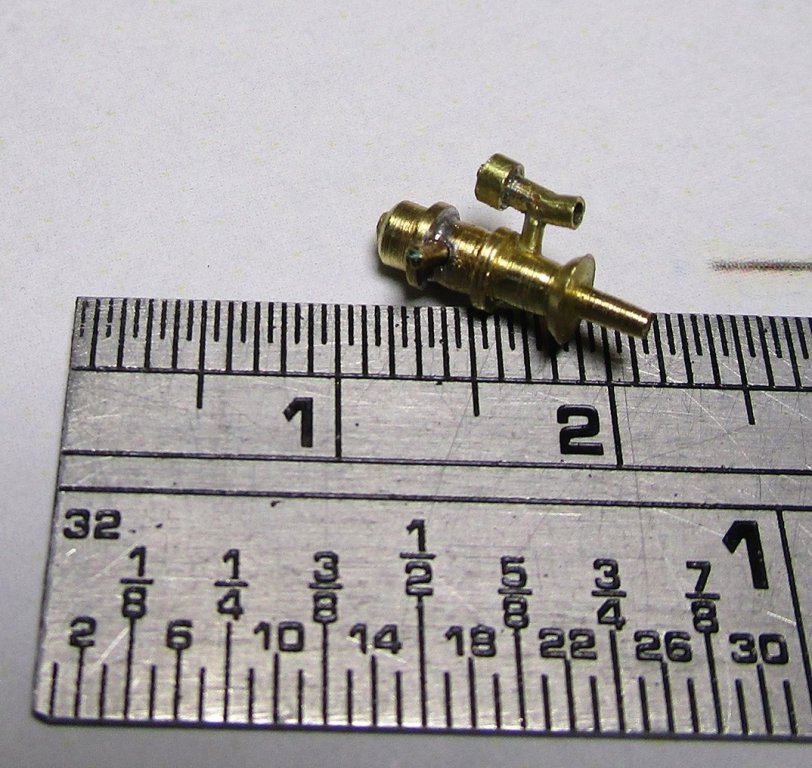
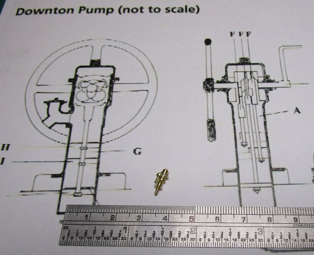
Hi again folks, no update for a while as I have been busy designing/drawing up the images for the PE I intend to use for the Victoria. this includes the chain plates, rigmaiden lanyards, patent purchase winches (halyard winches), handwheels for the downton pumps and winches, ventilation louvres and various brackets/straps. I have also made a start on the downton pumps - are these small? There were two of these (5") on the upper deck and another 7", probably engine driven, in the engine room There will be two suction plate assemblies between the pumps. I have managed to make three bodies that are relatively the same size (as best I could with my lathe) they are within .5 mm for height and diameter. With the spare, I experimented with the best way to fit the drive rod, onto which the round main turning handle, and the L shaped ancillary handle will fit. I need to find a better way to file the square onto one end of the rod (for the L handle) and I think I will do that before I cut it to length next time. i also need to try and make this outlet a bit smaller yet. This one is the spare as the bottom part of the barrel is slightly tapered and it should be straight. The photos show the spare pump with the rod, and the outlet spigot (two ended) with one end capped (as per the diagram as shown in the first photo). I have yet to clean this up properly but it is getting there; just need to add the round handle when they have been etched. The L handle will hang on the back of the engine room skylight. cheers Pat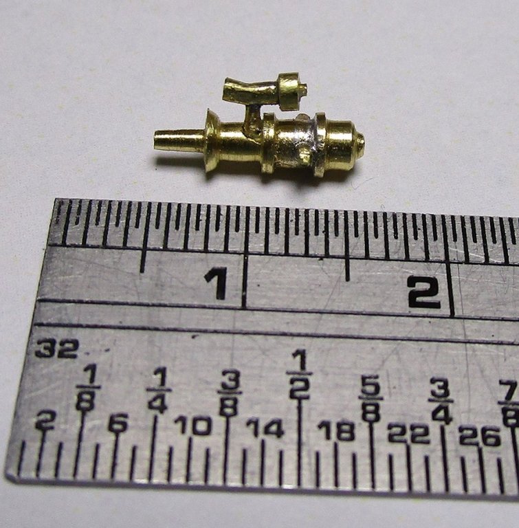

- 988 replies
-
- 10
-
-
- gun dispatch vessel
- victoria
- (and 2 more)
-
You're making some rapid progress there Rob; all is looking very good. We'll have a clipper under a full 'fit' of sail before we know it.
- 1,205 replies
-
- 2
-
-
- great republic
- clipper
- (and 1 more)
-
Nice progress Vossiwolf. I would not be too concerned with the gloss look. I had the same issue with a matt black on Endeavour where under lights etc it looked very shiny but to the eye in even lighting looked 'flat' - amazing how light can play such tricks! cheers Pat
- 624 replies
-
- 2
-
-
- lady nelson
- victory models
- (and 1 more)
-
Another interesting subject matter you guys are building; look forward to seeing the combined efforts. cheers Pat
-
Mark, not sure but I think think you need the Pro (Platinum) version of TC to do that? cheers Pat
-
Very nice work Steven, amazing what you are producing with simple tools (and patience). cheers Pat
-
The running end would need to factor in both the working room (length) needed to work the line, but also to allow the full/maximum extension of the tackle etc. Therefore the length of the 'tail' would vary. cheers Pat
-
Hi, I have not modelled with card so please take my suggestion with a healthy dose of salt Have you tried making a jig onto which you can lay out and glue all the parts (waxed ply or the like) and using small pins and strips of wood as the form etc. With pins in the locations for the fall blocks etc would it be possible to layout the davit tackle/falls then use Mark's idea to set them? cheers Pat
-
Hi Jim (assuming Jim?), One of the best references for rigging ships in this period is Underhill "Masting and Rigging the Clipper Ship and Ocean carrier". In this Underhill shows the dead-eyes turned in (the act of seizing the standing rigging round the outer score of the dead-eye). For wire or natural cordage shrouds the tail is shown seized back onto the shroud; and, provides some drawings of how it was done. As this book is in copyright I can't post pics etc here. For reeving hearts, there were several ways and for these the tail of the lanyards were seized back on themselves. These were sometimes used on some stays etc (especially on the bowsprit) but not usually the shrouds. Perhaps this may the source of confusion? cheers Pat
-
That is a great painting mate. Amazing fact that although the number of sails was increased, the actual sail area was reduced. Do you know whether this was this intended to make sail handling easier, or reduce the strain on the masts or ...? cheers Pat
- 1,205 replies
-
- 2
-
-
- great republic
- clipper
- (and 1 more)
-
I am always impressed with the quality of your work Amalio. The workmanship is simply stunning! cheers Pat
-
Maybe small but still significant progress UV; the servings look good - tight and even. cheers Pat
- 786 replies
-
- 2
-
-
- Royal Louis
- Finished
- (and 1 more)