Snug Harbor Johnny
-
Posts
1,510 -
Joined
-
Last visited
Content Type
Profiles
Forums
Gallery
Events
Everything posted by Snug Harbor Johnny
-
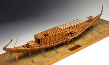
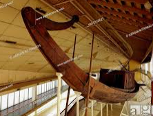
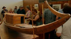
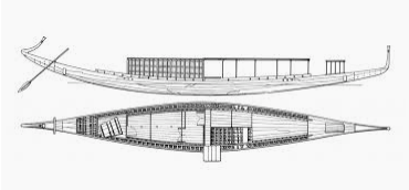
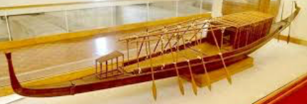
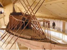
 'Looked for images of the museum ship and replicas to get some ideas on how to represent the model ... not really 'busts', but perhaps preferable v/s how the ship is shown in the kit materials. One version with the rowing positions shaded. Note above & below that there is one pair of steering oars. The real deal below. A large scale model at the museum. BTW cross beams did support the removable hatches. Oarsmen may have stood and rowed by pushing out and back (varying the blade angle each time), similar to a Far Eastern method of rowing. Another view of the restored ship on exhibit Just more 'food for thought' ... why rush?
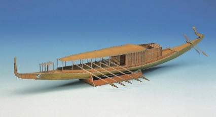
- 63 replies
-
- 4
-

-
- Finished
- Khufus Solar Boat
- (and 1 more)
-
You might try making a form with a mild bend (placing a pencil beneath a phone book?), placing the warped piece on top aligned with the curve (but opposing), then letting a ream of paper (or another phone book) lay on top to 'force' the deck into curving the other way. Left overnight, it may 'spring back' to approximately flat ... possibly a trial-and-error process by adjusting the re-bend as needed.
-
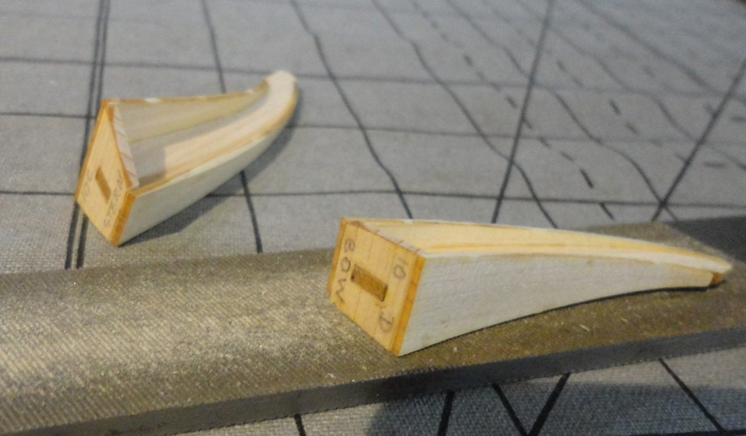
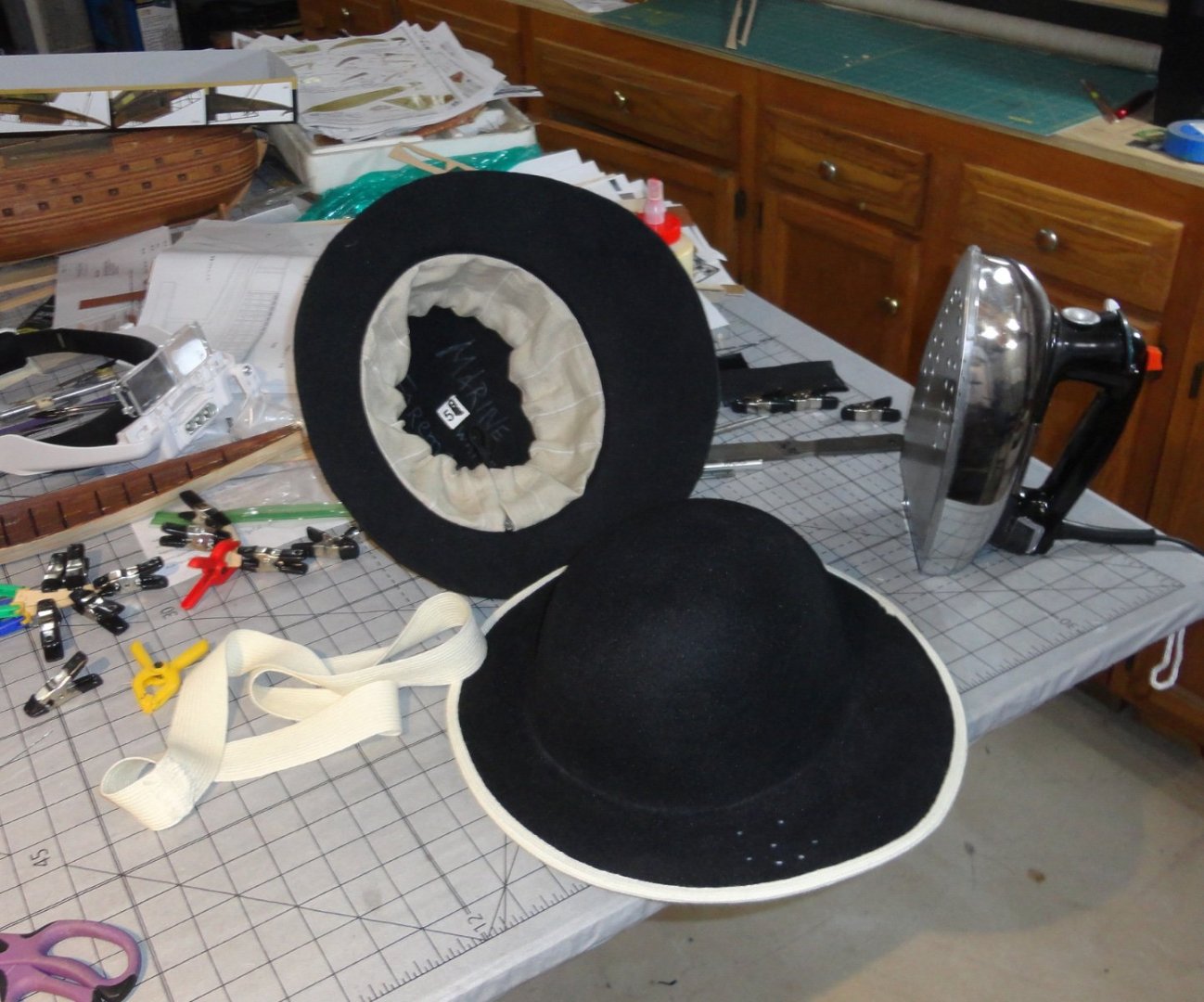
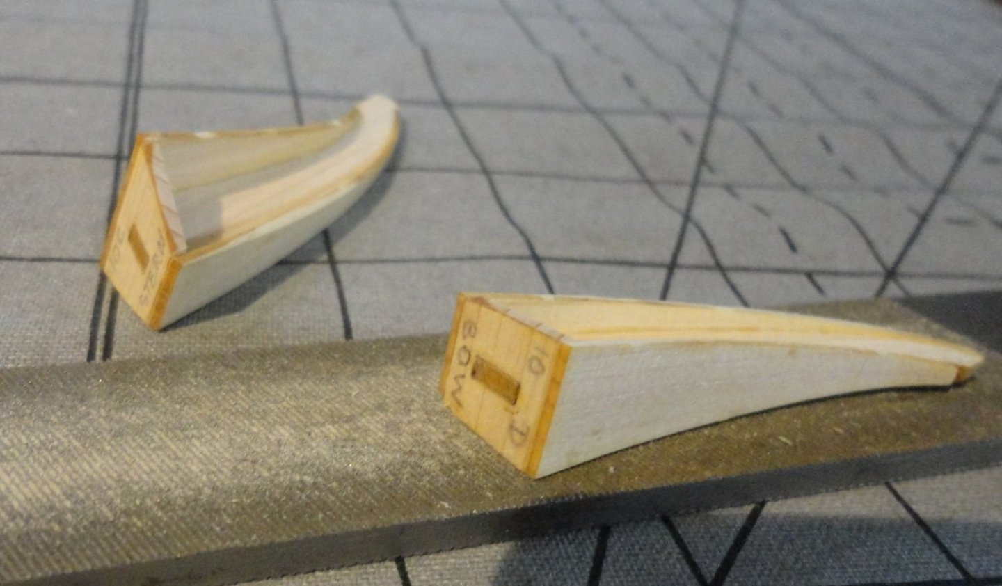
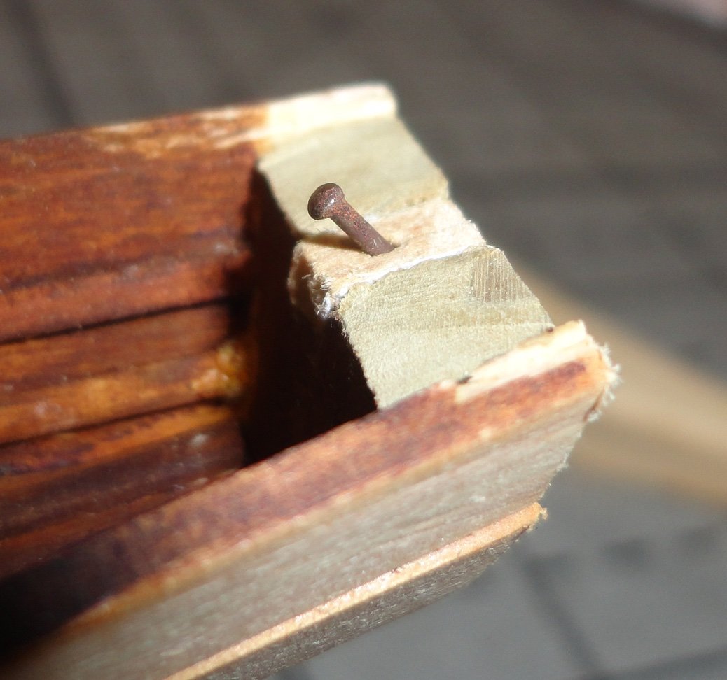
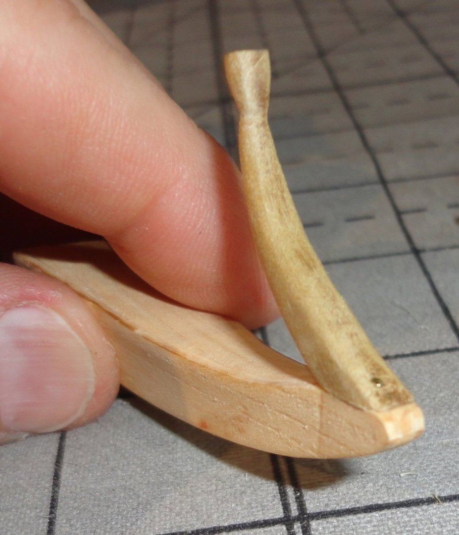
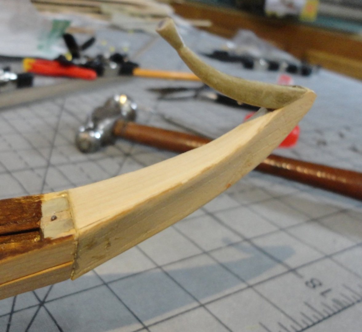
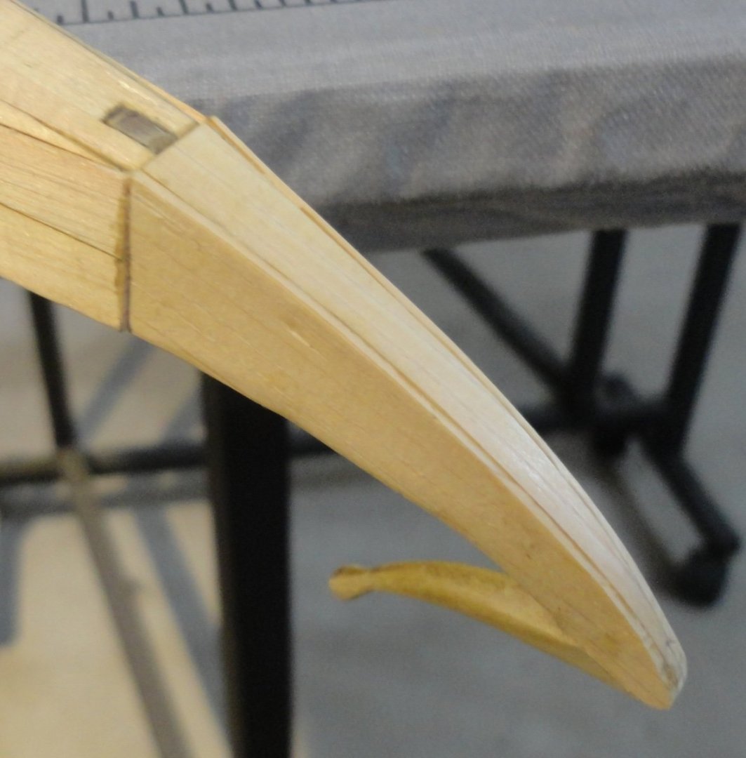
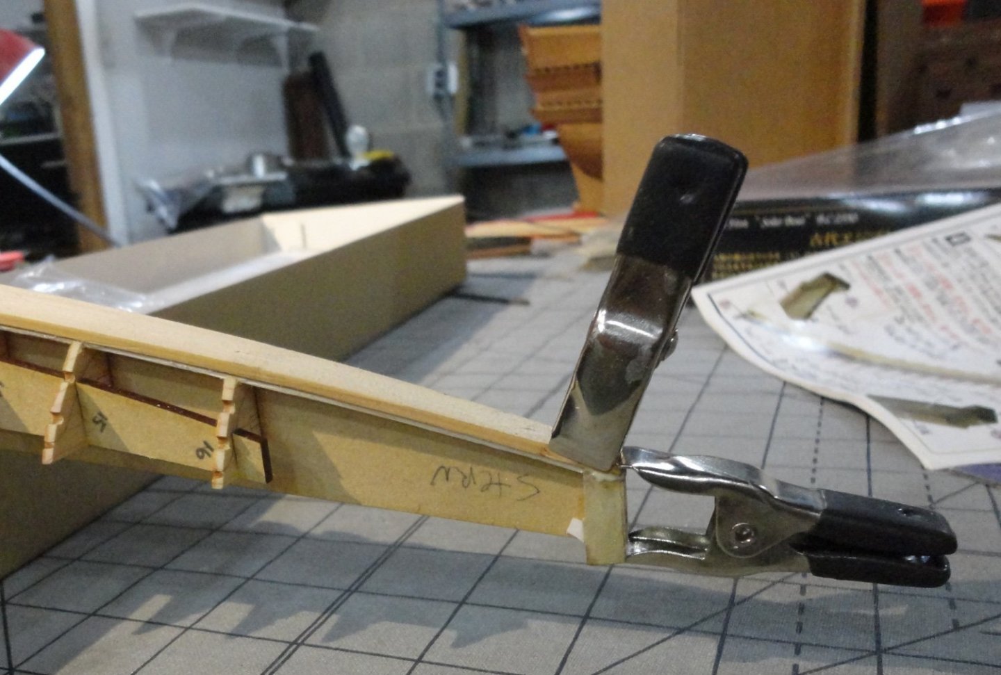
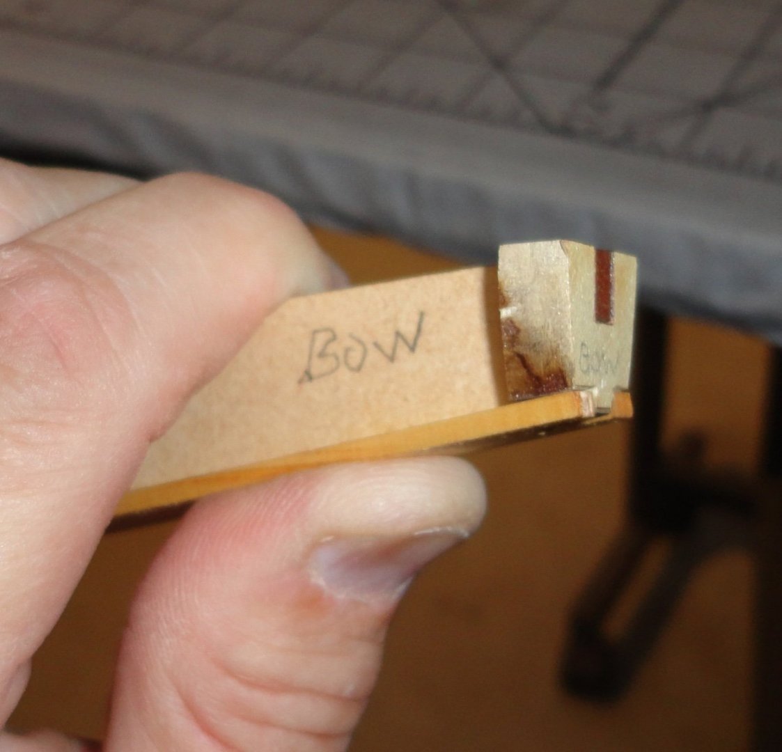
'Been put to work on an Admiralty project for a few days ... also had to finish a hat order - the last two done this morning (cut down Colonial Marine hats). Sometimes the Admiral thinks I'm a 'mad hatter' of sorts. Well, this sideline is part of her cottage industry and I'm 'in for the duration'. The adjustable liners are sewn on a 100+ year old Wilcox and Gibbs hat machine - reconditioned and maintained by yours truly. Back 'on topic' ... Another reason for the break is that I was re-thinking the 'plan' mentioned in my last post. Ah, 'The best laid plans of mice and men oft gang aglee.' By that I mean that I thought of four other approaches to what still seemed to me a 'sticking point' - the attachment of the delecate ends to the fore and aft end pieces, then the attachment of those assemblies to the bow and stern blocks with something more substantial than just butt joints. 'Didn't know how to clamp (having discarded the 'use a screw' idea) and I didn't want to use 'finger clamps' for an hour. So I settled on the idea of pinning and decided to just forge ahead ... "Screw your courage to the sticking place." First I had to fair the sides of the end pieces - done with a file. Then the ends of those pieces AND the faces of the bow and stern blocks had to be flattened to meet flush - also done with a file. As for the angle to trim the end block to ... I decided to look at the full size plan in the kit - what a concept! (Duh.) 'Still don't like their 'stacking' of the auxiliary deck pieces, but I can do it slightly different. An X-acto was used to trim (carefully) the unwanted material to get an approximation of the defending angle needed - it will be covered-up anyway. Below is a trimmed block and putting the side pieces on one of the end extensions. The uncovered piece on the left has had extra wood glued to where it will join the hull. Then the thin end projections had to be carved - so I whittled the first one (bow) to rough-form, and finished with small files. The stern end on the right (below) has yet to be shaped (for comparison). There is some real modeling involved to it. OK, now to 'brass tacks' (actually one still and one brass for each end). I plugged the notch in the stern end with part of the 'central keel' used earlier in construction (now removed) because that piece had already been shimmed to fit closely. I used a #60 drill to hand-turn a pin chuck to get a pilot hole for the steel mini-brad (found in old Billings or Steingraeber kits). The plug was glued-in and the brad pre-placed to push into the end piece to be added. The next picture is out of focus, but I glued the stents projection (now carved and smoothed) with a tiny brass pin included in the Khufu kit. Hmmm, my opinion of them has gone up. The obsolete (Admiralty cast0off) camera I'm trying to use keeps shifting itself from ordinary pictures, to video filming, to 'close up' mode ... at random. But below is a relatively focused shot of the pin now pushed in . I intend to get a pin (brad) 'pusher' that will work better than the plier ends or a file end. With the pin in place, the end projection (lotus) is reinforced and feels relatively firm. Once the glue cures, it will be strong enough. Hey, you know how delicate bowsprits can be ... especially the ones on plastic models - and even more delicate are the cathead whiskers or martingale on the Revell Cutty Sark kit. So why should I worry about glued wood that is thicker? Ahhh, the light at the end of THIS tunnel (doubtless there will be more later). The stern end is glued and pinned and after curing can be further faired. A view of the underside. Now both ends are inlace and I can relax a little. BTW, the Khufu model is about the size of the Wasa project (1:100 first Billings version) ... just under 23". That is not too big and not too small. Getting this far with the Khufu kit has involved enough modeling skills that it is no 'pushover' for a 'beginner' - yet affords real opportunity to gain experience (as long as one has a little patience) and is wiling to repair the occasional mis-step ... something we all have to do.


- 63 replies
-
- 6
-
-
- Finished
- Khufus Solar Boat
- (and 1 more)
-
Very interesting photo ... likely among the changes made in South America before departure for Antartica. It shows that the original installed side railings of the central cabin were removed ... and that cabin was enlarged by decking out to the gunwales AND rearward to the stern cabin to make one giant living space for the long Winter(s) ahead. Check out the ingenious build log of the Endurance (ex Polaris) in a lightbulb done not long ago, where the builder's intent was to show this "final" (so they thought) configuration of the ship deep into Polar ice. I had not realized just how extensively re-modeled the ship was, but a careful examination of the many photographs extant (and one has to 'dig' a little to see some of them, as many institutions/individuals have got into the habit of 'copyrighting' any old photo in their possession - even though the material was already in the public domain from the passage of time alone, plus prior publication) reveals that a major re-decking (via extension) was done. So there are many 'configurations' to choose from when deciding what point in time/circumstances to represent in a model. Aside from the original Polaris (enough photos exist), there is the 'mod 1' version of Endurance as it set sail from England ('T' shaped walkways w/railing and 2 side gangways to make a dog run with railings, kennels present but no enclosure over the steering tackle), a 'mod 2' with some further changes done upon reaching the Americas, and a 'mod 3' version of even more extensive modifications (a-la the above mentioned cabin/deck extensions) prior to finally leaving for Southern Polar waters (not sure when the steering tackle was enclosed, but certainly by 'mod 3'). Take your pick, for they all represent the ship at some point in time. When trapped on the ice, more changes were made e.g., an observation perch was constructed at the stern and accessed by a long ramp (gangway) with side safety ropes (or cables). Once the decision was made to camp on the ice, the enclosure for the steering mechanism was moved off the ship as a ready-made cabin ( and the wood from the observation perch and access-way re-used ... with a lot of other stuff as needed) - ergo that is why you can see that area un-enclosed on the recent pictures of the ship made in its final location under water. 'Problem is: one can't just use ALL of the stuff seen in one photograph or another at the same time, since some of the configurations are mutually exclusive. So a builder should choose one point in time/location and try to include the features documentable to that point. Many one this site have seen the extensive build log of Rob's Glory of the Seas clipper, and just how much information came from examinations and re-examinations of both photographic and written documentation. The LATEST revelation being that the forecastle was taller and roomier that previously thought since the forecastle deck turns out to be higher than thought - proven by comparison of multiple photographs. So Rob is in the progress of re-building this area on the model, since he has lavished so much attention to accuracy of a particular TIME in the life of the ship. This we see that there are MANY Endurances, just as there are MANY Glory of the Seas (or Thermopylaes). Once agin, take your pick. Fair sailing ! Johnny
-
The approach OcCre uses to build ship's boats from simplified framing ('skeleton') is a good compromise - I may use the method elsewhere. Another build log posted a method of bending more scale-like ribs over a form, then adding a keel before planking. 'Guess it all depends on how much work one wants to spend on a little boat. Any method using wood is still better than just painting a cast metal or plastic dinghy.
- 43 replies
-
- 4
-
-
- Mayflower
- Model Shipways
- (and 1 more)
-
You are right, of course ... but somehow I was thinking that Katherine Hepburn used that line in an historic sort of film. 'Tried going through the film script of Lion in Winter, but didn't find it there (or missed it somehow). 'Tis true 'tis pity. Pity 'tis, 'tis true. (Polonius)
- 63 replies
-
- 4
-
-
- Finished
- Khufus Solar Boat
- (and 1 more)
-
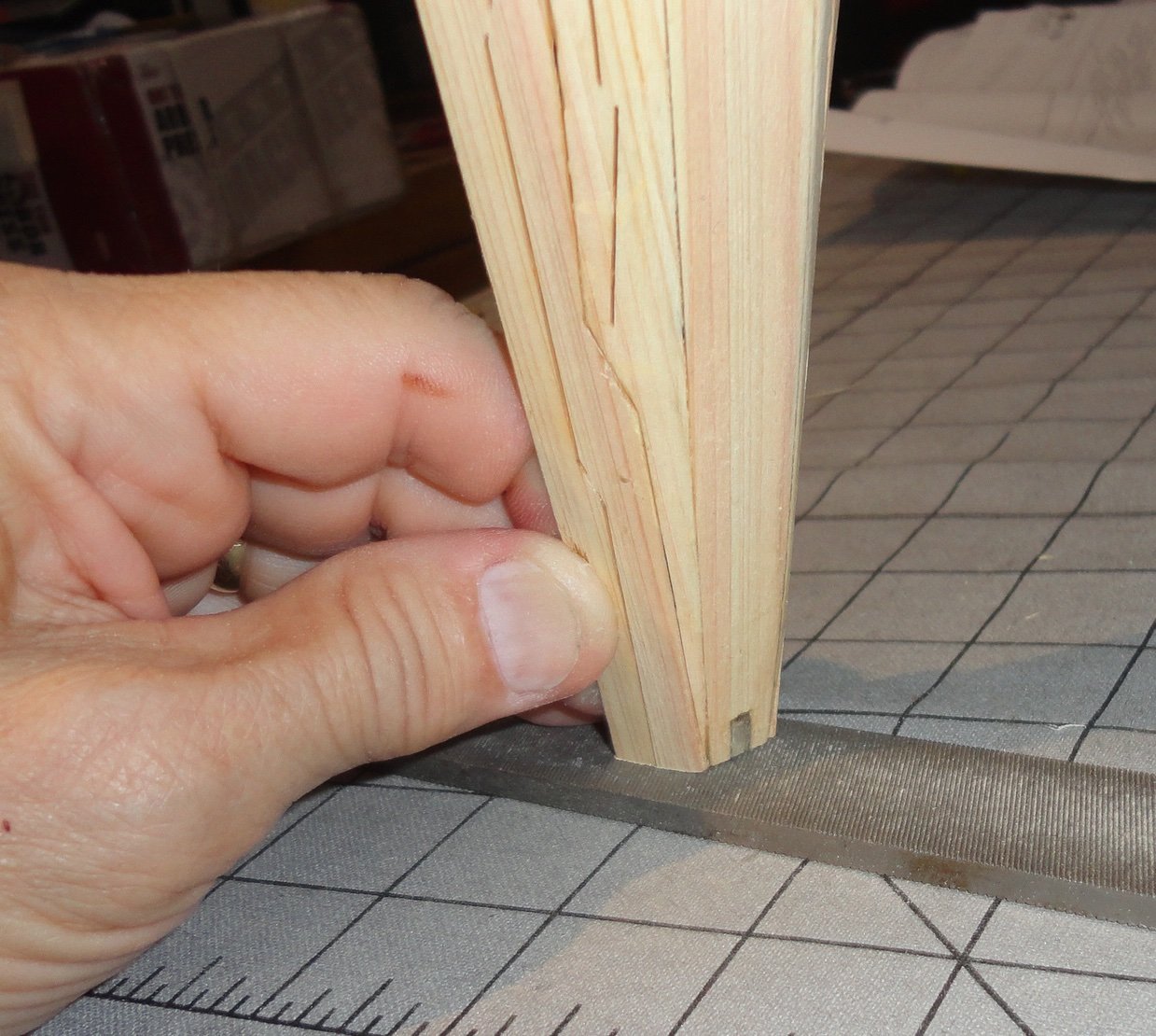
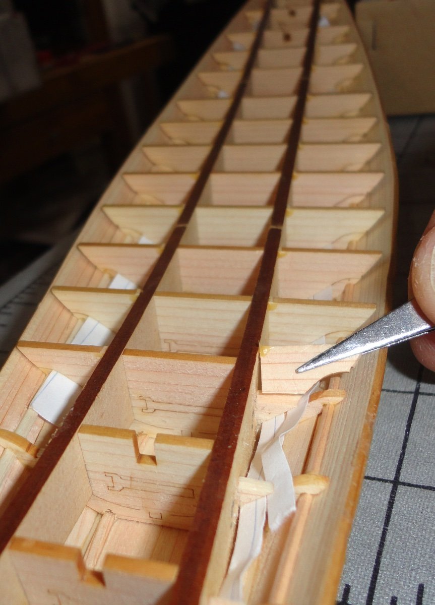
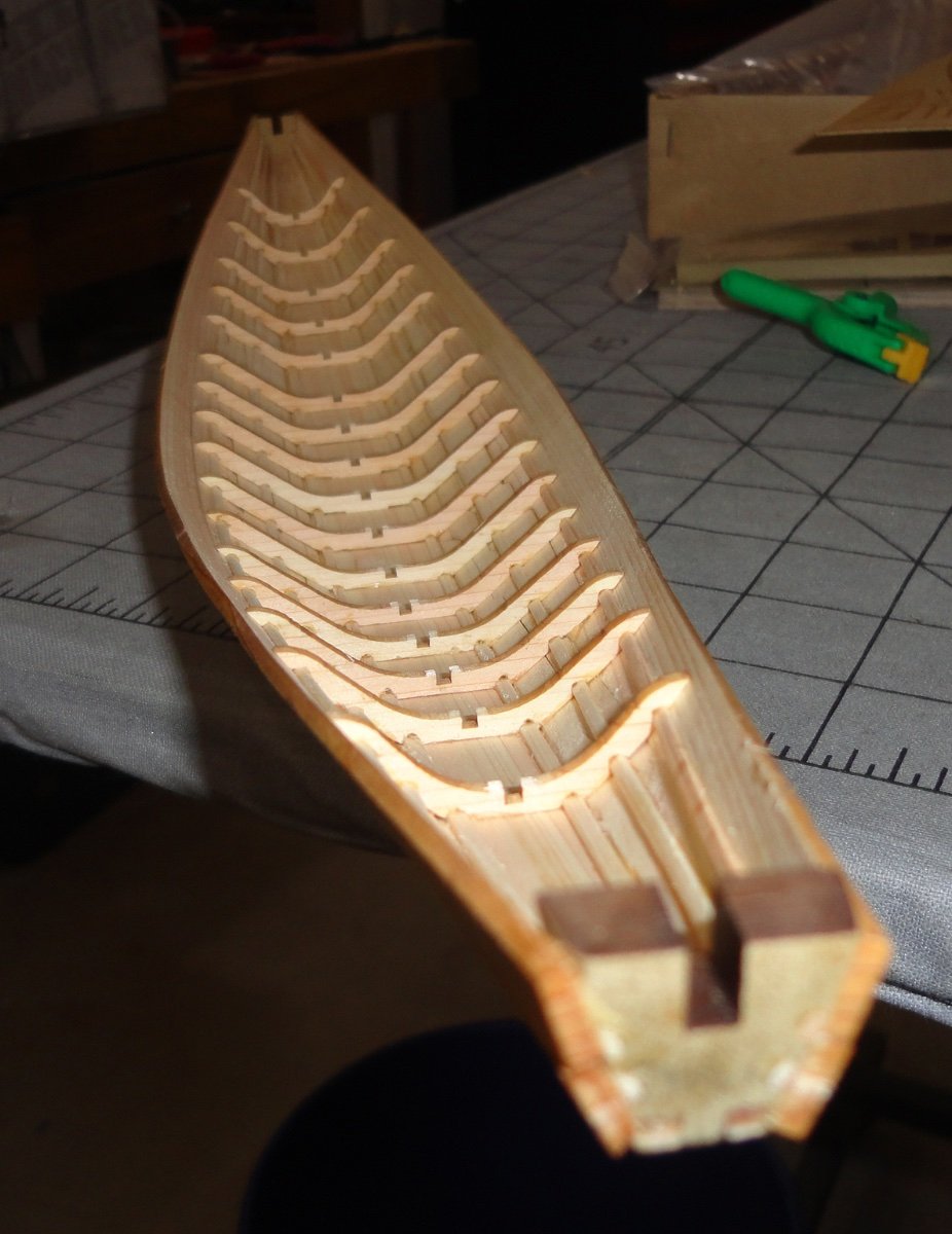
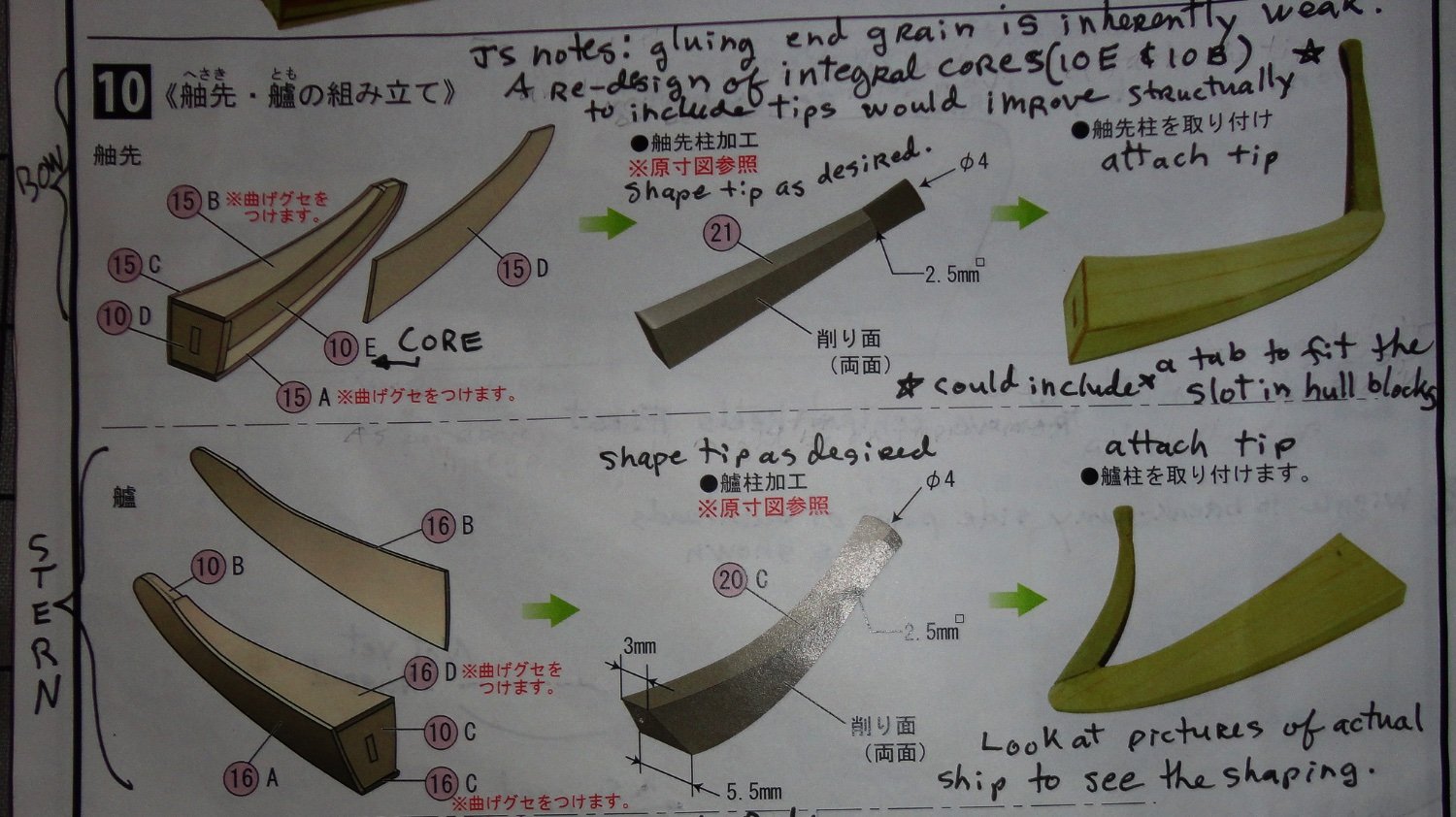
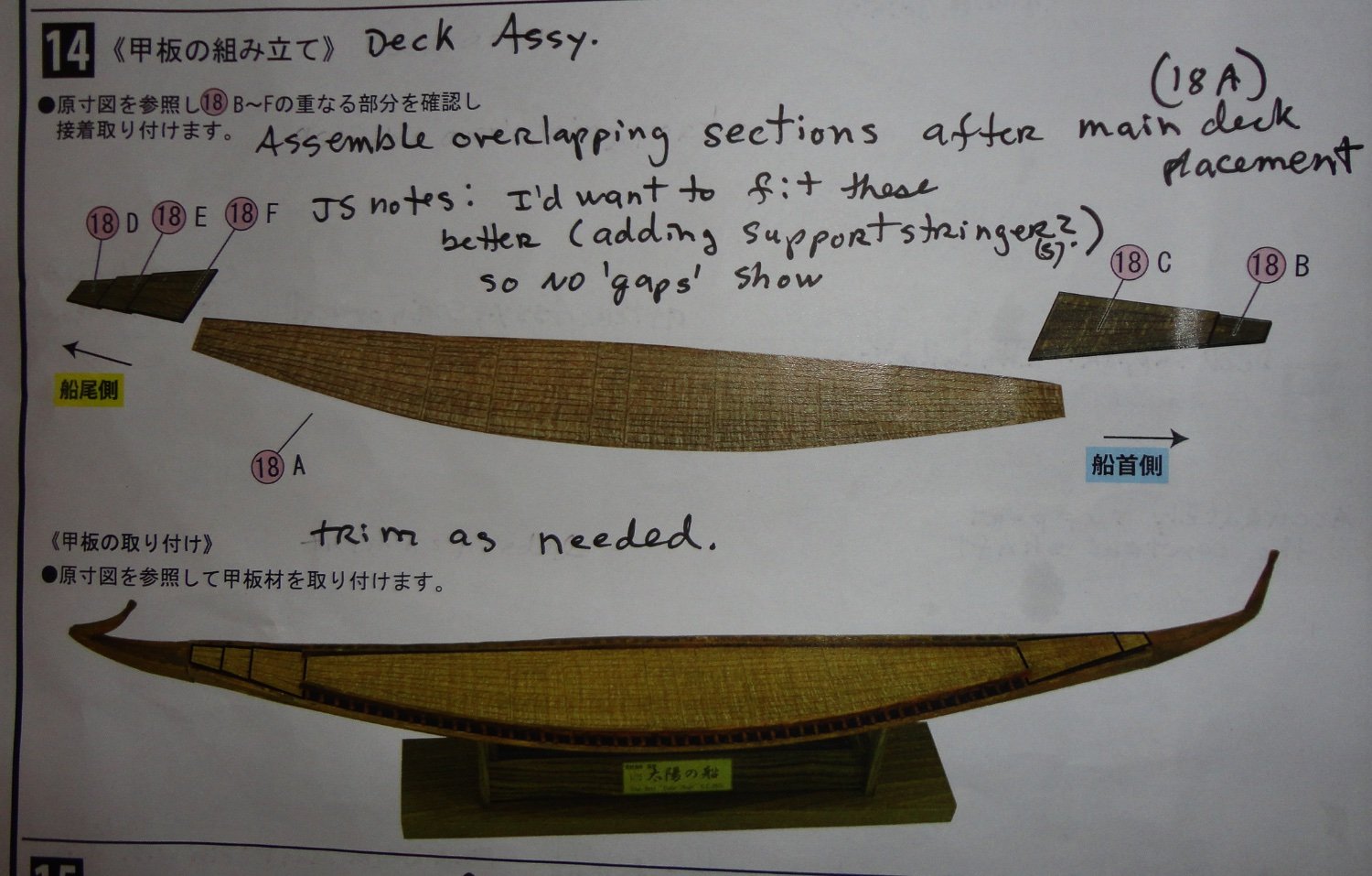
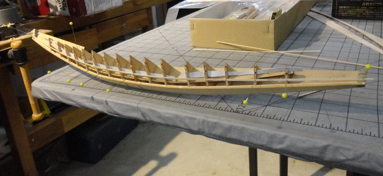
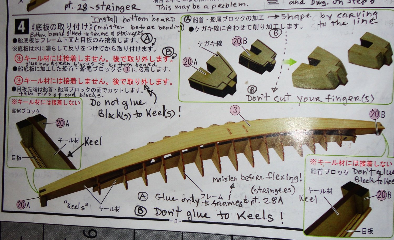
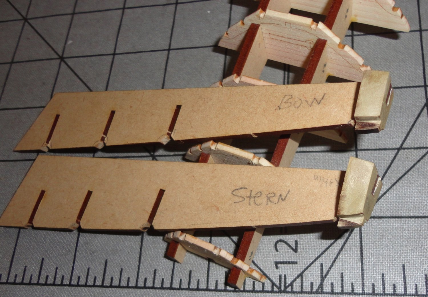
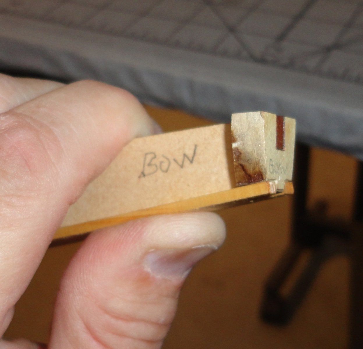
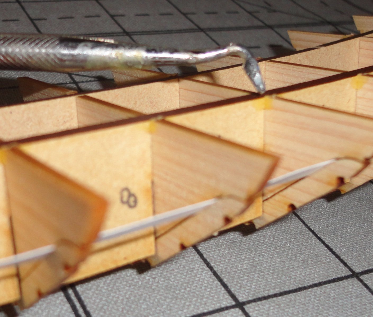
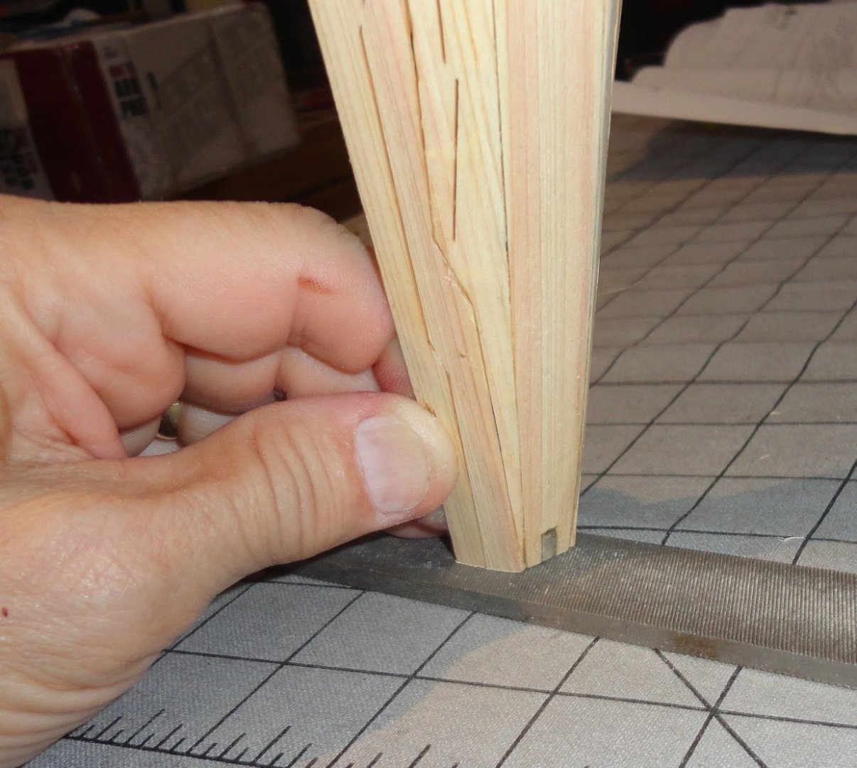
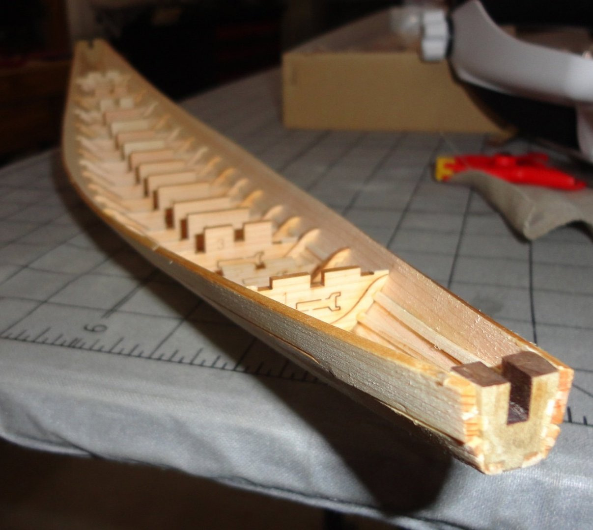
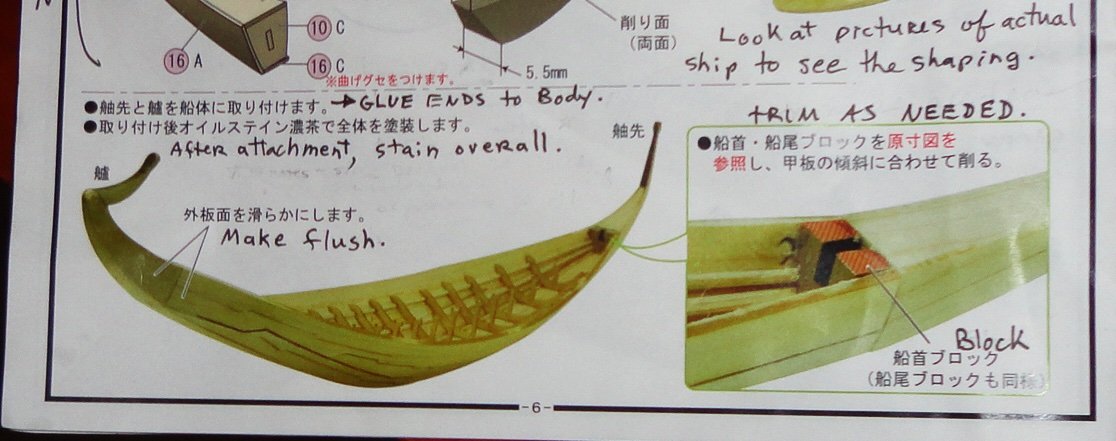
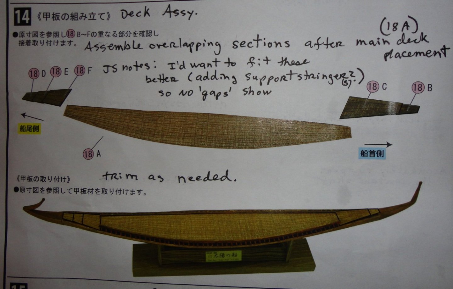
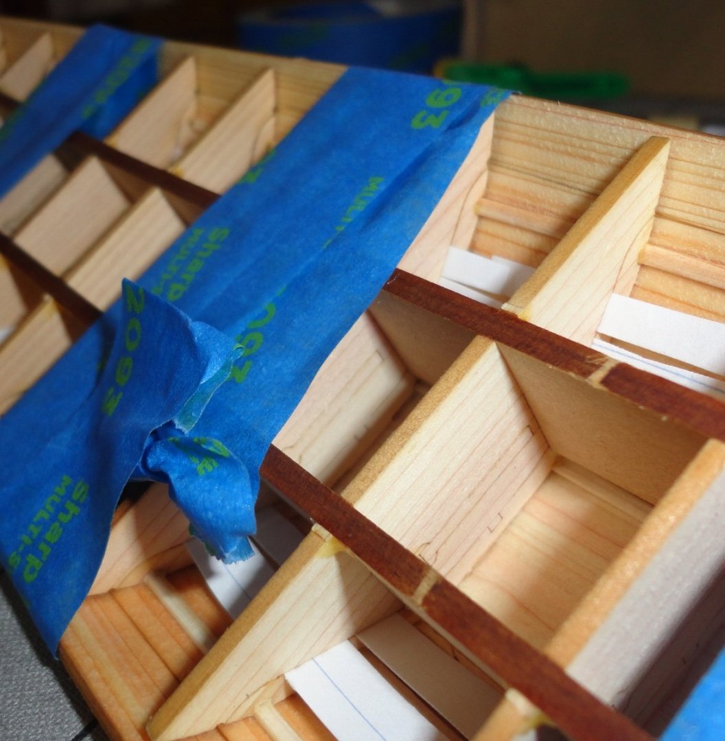
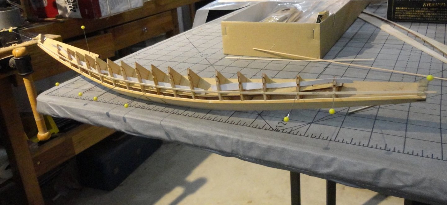
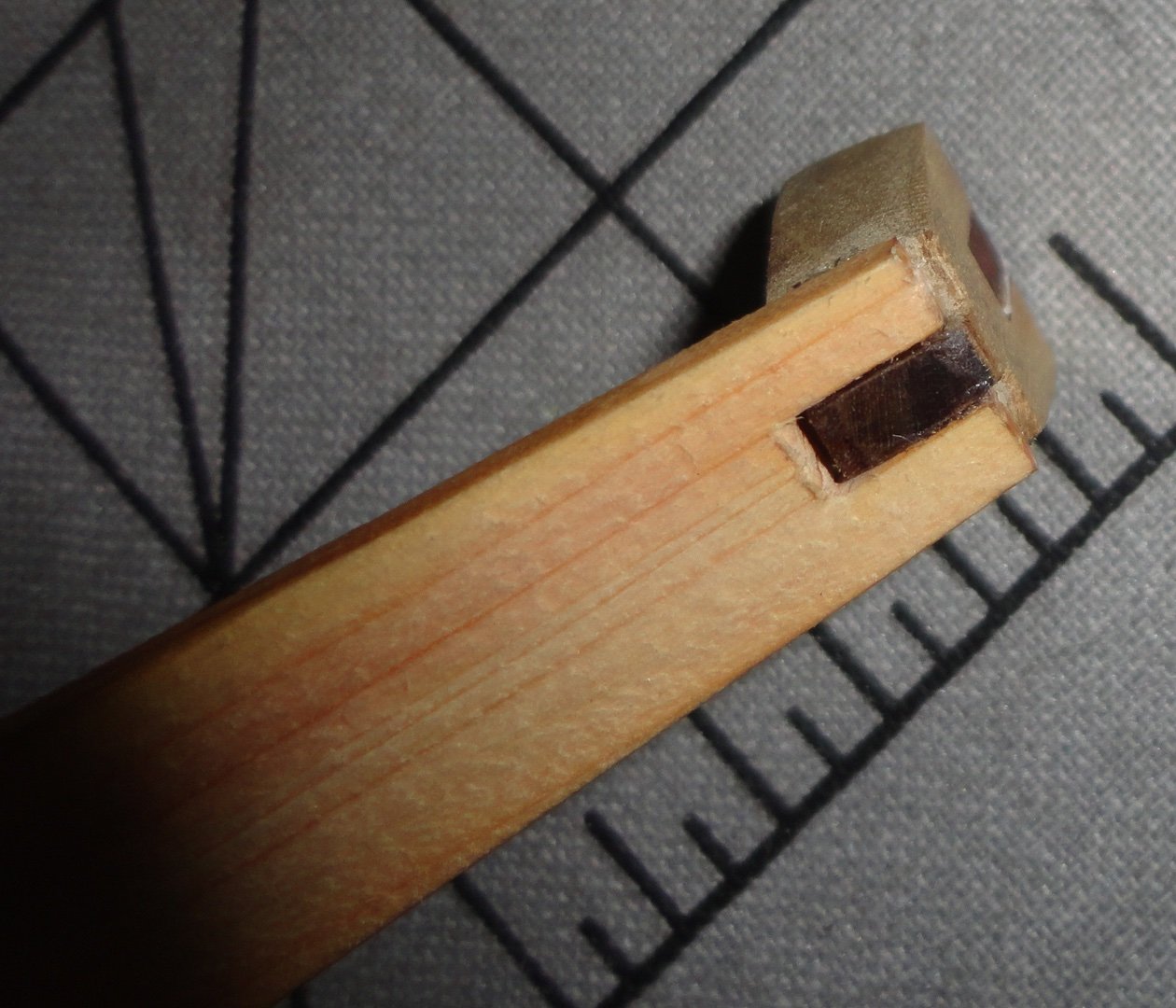
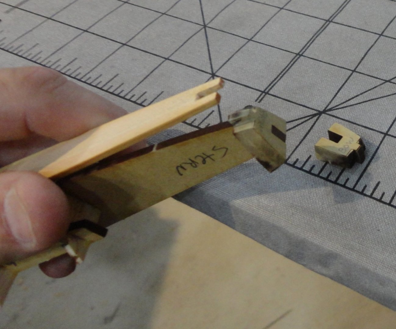
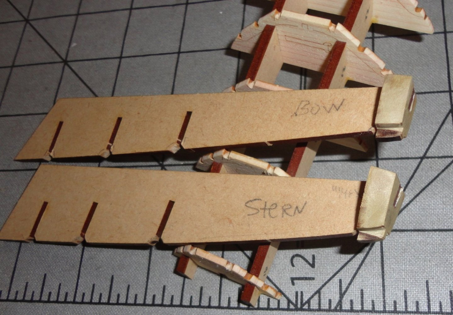
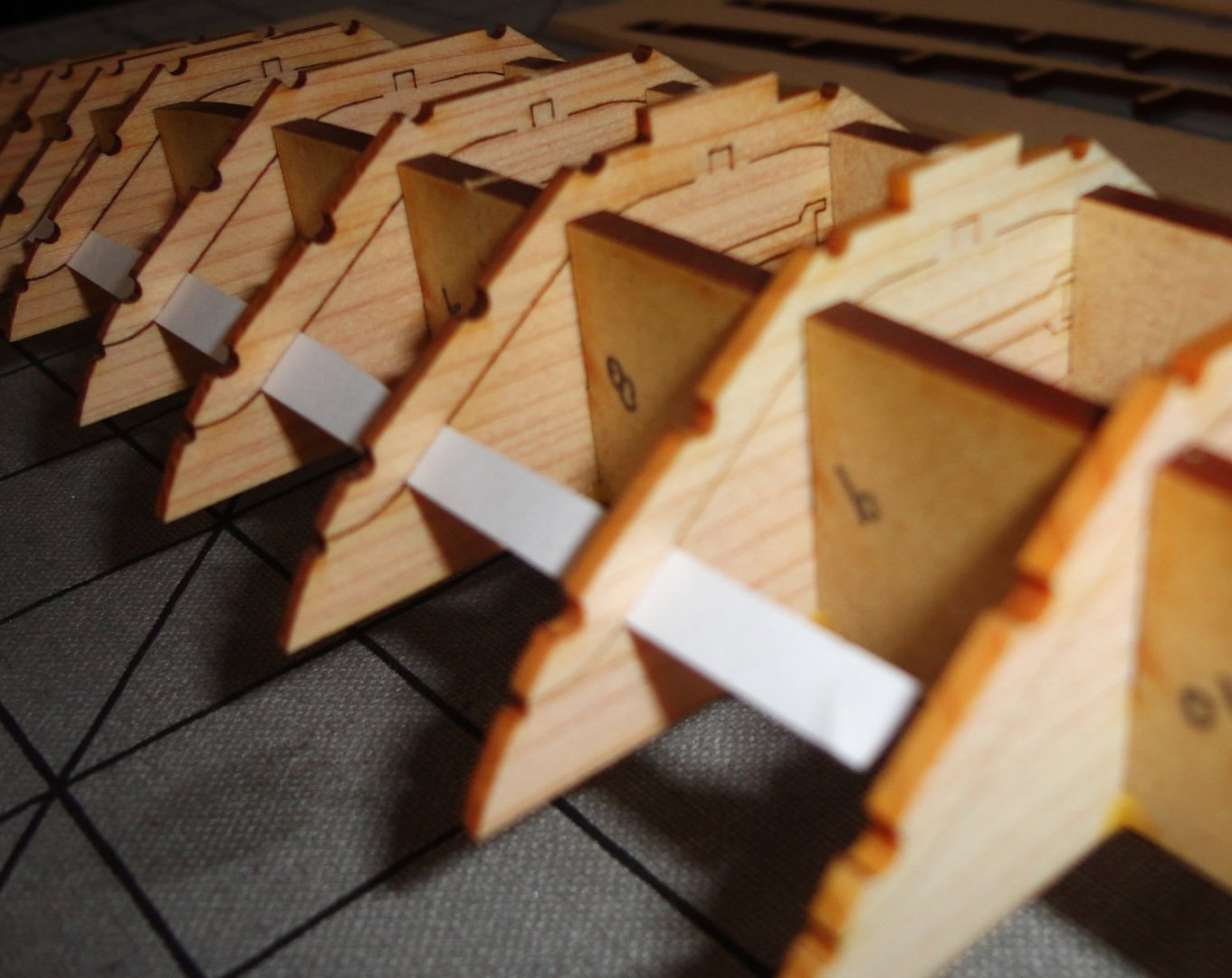
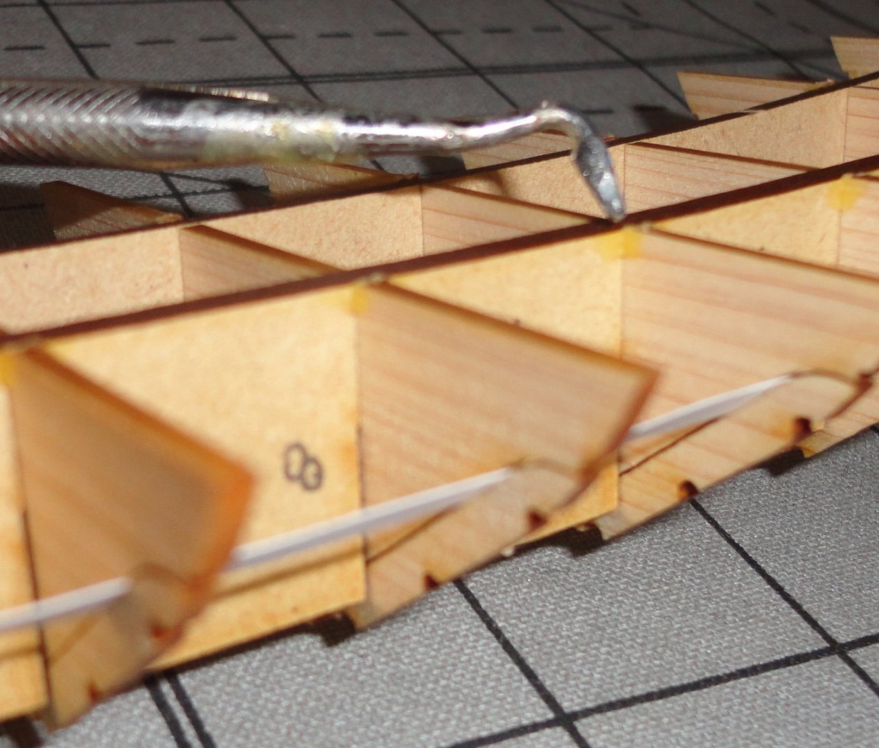
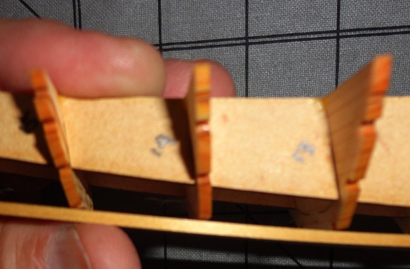
'Had a couple days to ponder some additional work AND some changes to the assembly order ... there were just a couple things that didn't 'add up', and sometimes it pays to think of a build as a 'chess game' - where one needs to be thinking several moves ahead to avoid trouble. Step 8 (not pictured) merely instructs the removal of the 'central keels' at both ends, which was easy since there was no glue holding them back. The 'safety notching' made earlier prevented trouble. Then step 8 instructs to wiggle the outer portions of each frame (bulkhead not attached to the ribs) to remove before taking out the side 'keels'. Below is a photo of this process. This was easy, and the next photo shows the hull after the pieces were snapped off and the keels removed. Then the middle portions of the bulkheads came away easily, and were set aside in a bag, since there are little supports contained in each corresponding to the middle of the rib they will have to be glued to - and they will support the under beam for the main deck cross beams. Since I took time to fair the ribs and stringers, there is pretty good contact (cemented) to the planking, and the hull seems to have a lot of strength - resisting torquing ... of course there is always a limit and I made sure to only apply enough pressure to test the structure. So far so good. Step 9 (not shown) instructs the supports of the central deck beam to be installed ... but it seems best to hold-off on that for a couple of reasons. a.) there is some adjustment work to be done yet, and b.) they will be very vulnerable to breakage and may also make tinting the interior of the hull more difficult. I will show step 10, which appears straightforward. But "there's the rub" (quoth Lady MacBeth). The lower part of step 10 has one face-glue the ends (a weak sort of joint) to the hull, with the projections already having been face-glued. Then the end blocks are to be trimmed 'as needed'. To what angle, I ask - and how is this to be determined? I have to jump ahead to step 14 to get a clue. 'Sorry that this picture is dark, butter the main deck beams are constructed AND the main deck installed, there are additional sections (removable on the original ship for access below .. guess they are equivalent to 'hatches'.) Two are fore and three aft. The first fore and aft fit into the longitudinal beams holding the deck support beams (widthwise) and are supposed to angle upward. The next pieces are 'bridged' between that first piece and the respective end block. I've seen photos of completed kits where they just don't look right compared to the original (or the large-scale model in the Egyptian museum). To make a long story short, I'll choose the the following sub steps to arrive at a solution: a.) Tint the hull interior with a water-based colorant. Then assemble the internal vertical supports for the center deck beam and touch them up with colorant. Rough mate the bow and stern end pieces to fit together at the faces. b.) Assemble the deck support beams. c.) Test fit the beam assembly into the hull, and add the first fore and aft deck hatches to see what angle they need to rise within the hull. I want to have a cross support member at the end of these parts. Then the bow block can be angled so the second (forward) hatch can lie properly - bridging the gap without rising above the planking. The stern has two additional hatches to bridge the gap (the end pair will be glued together for the purpose of getting the angle of the stern block correct. When test fitting is complete, the hatches will be reserved and the deck beams removed. d.) A filler piece will be made to fit the slots of the end blocks, and a hole drilled to accept a small screw before the slot fillers are glued in place. Additional wood will be added to fill the voids of the end pieces before they are covered by the side panels. I'll try and have a pin to strengthen the small end projections, which otherwise seem especially vulnerable. e.)The ends will be glued and the screw will provide the 'clamping pressure' between the end blocks and their mating pieces. Putting blue tape at the edges of the joint pieces will prevent squeeze-out glue from getting on the exterior of the planking at the join. f.) The deck beams are tinted where they will show, then the deck beam assembly is added and glued to the hull. The deck is added, then the hatches - and they can be tinted. f.) Once cured, the exterior of the hull can be faired as suitable - then tinted as desired. 'Sounds like a plan mates, so we'll see. Step a.) begins in then photo below.


- 63 replies
-
- 6
-
-
- Finished
- Khufus Solar Boat
- (and 1 more)
-
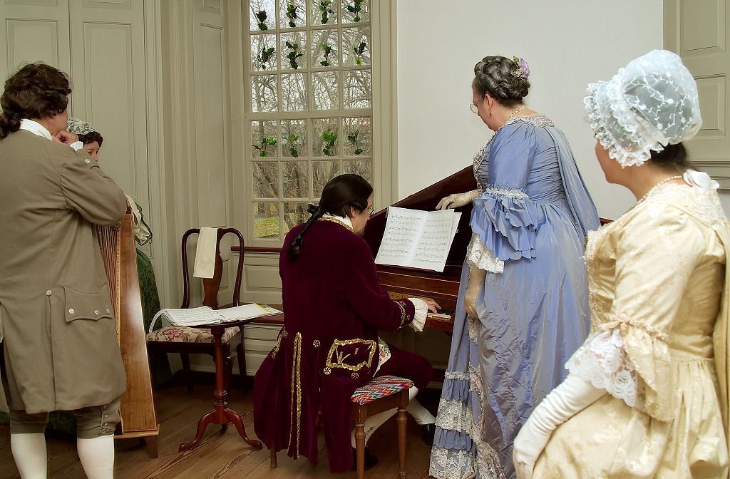
Only a few (maybe 4) needed narrowing from being cut too wide. I built the Baker Harris English bent side spinet from Hubbard Harpsichords (one time kit supplier) between 1985 and 1987. I took extra care with the veneered parts, even veneering the back and bottom of the instrument. The keyboard transposes (my kit bust), but due to the geometry of the instrument (as opposed to a 'regular' harpsichord) the transposition is an entire step (note). The idea was to tune at A 440 (modern pitch) and transpose for period pitch (A 415), but a full step is way too much (lower) and one loses notes at the top and bottom of the keyboard when transposing (not that those are used very much). Lowering string tension much below 90% of breaking strength 'muddies' the tones produced ... instruments should produce a clear sound - with steel having more of a 'ping' in the treble, and brass having a mellow sound. Phosphor bronze is another matter. Since building, I've hauled it in a padded case to several historic (Colonial) sites in the area to perform for special tours, and also play for English Country dancers. These days it stays put at home. The string scaling 'as built' is identical with an original from the Baker Harris shop (London) that the Connecticut owners allowed Hubbard to copy in return for restorative work. Brass stringing (intended for the instrument) breaks a lot in the middle range at modern pitch. My conclusion is that the problem is a combination of period pitch being lower AND that period brass had more impurities - giving it a higher tensile strength. I devised a second inner 'nut' (paired with the bridge on the soundboard, the string length is determined) for the middle portion of the scaling that adjusts the string lengths (shortening slightly) so that they can sound at about 90% of breaking strength at modern pitch ... they rarely break , yet provide good sound at A 440.

- 63 replies
-
- 7
-
-
- Finished
- Khufus Solar Boat
- (and 1 more)
-
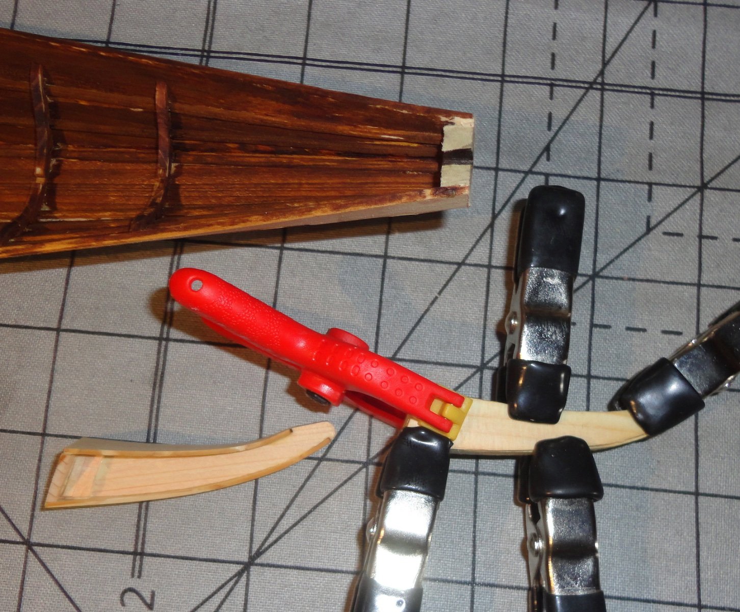
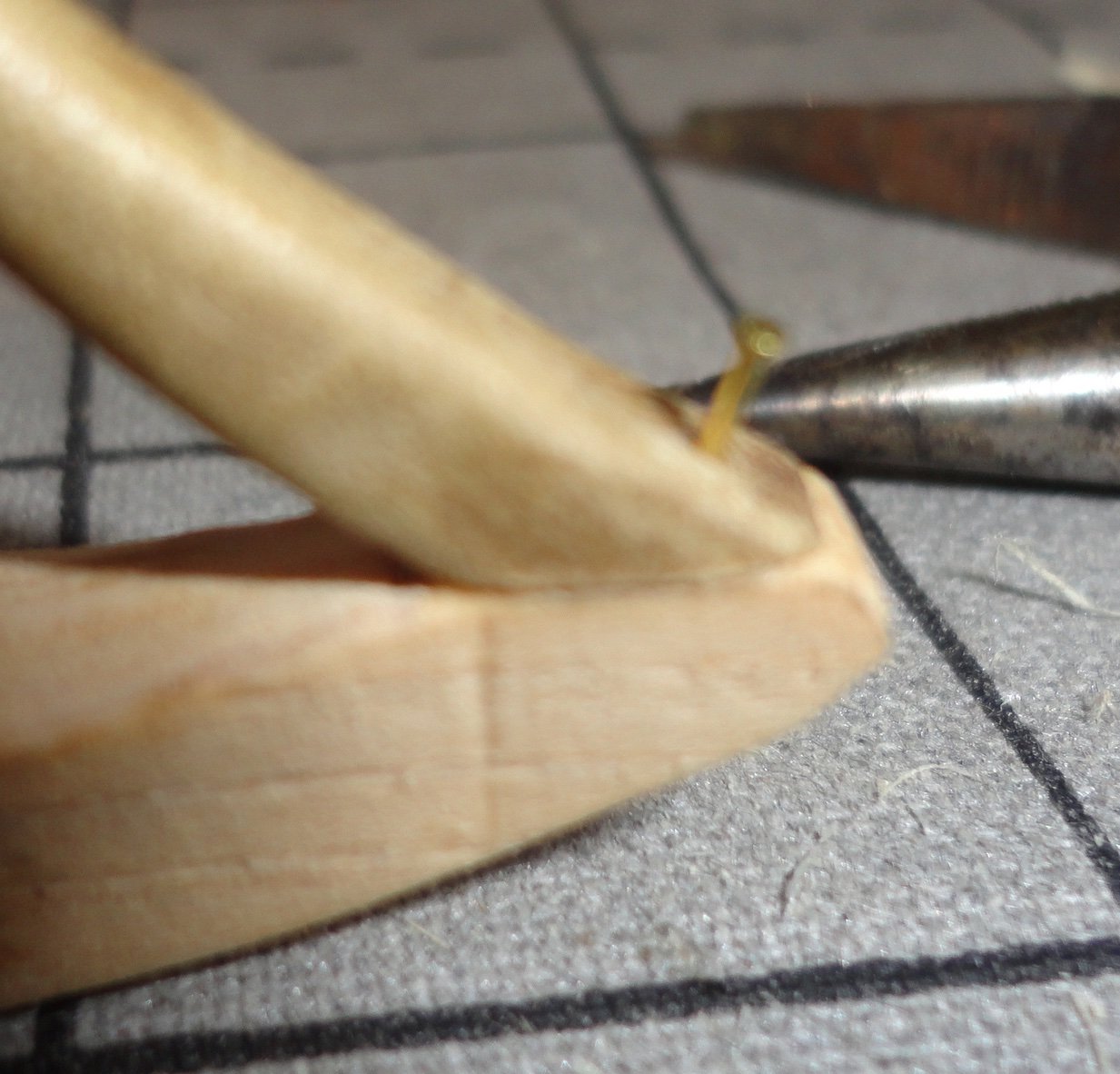
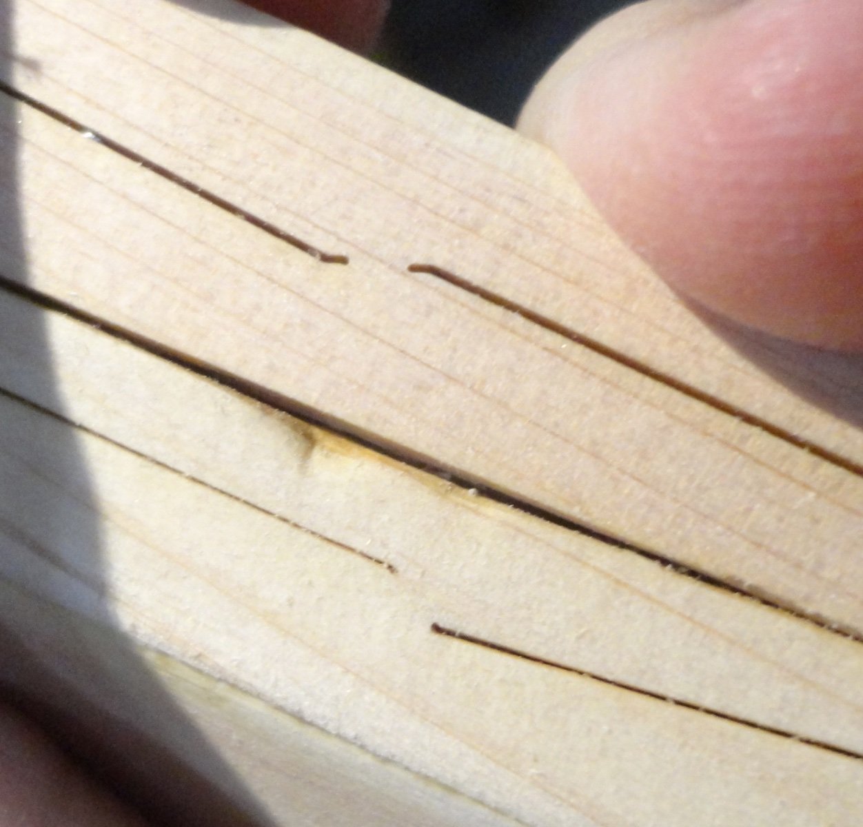
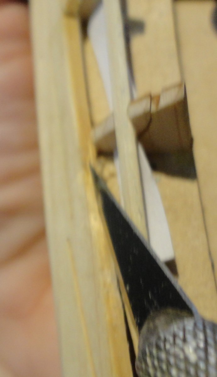
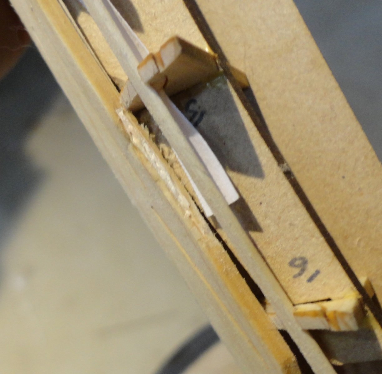
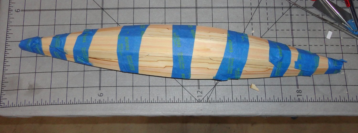
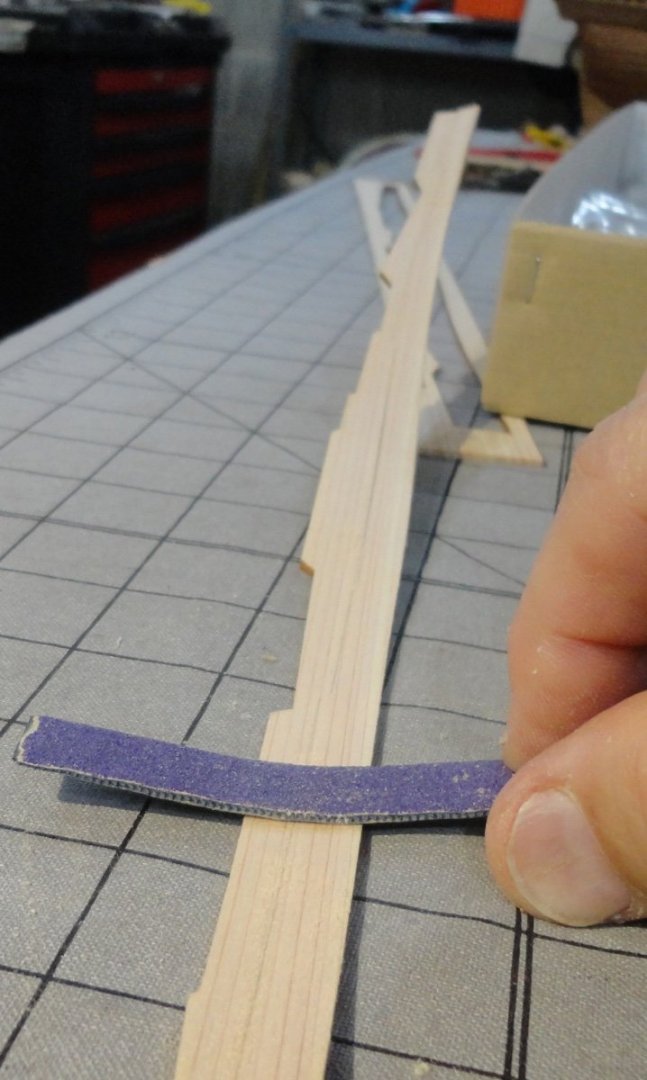
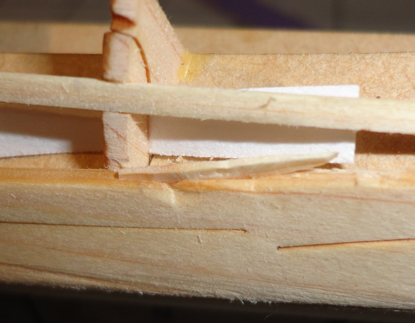
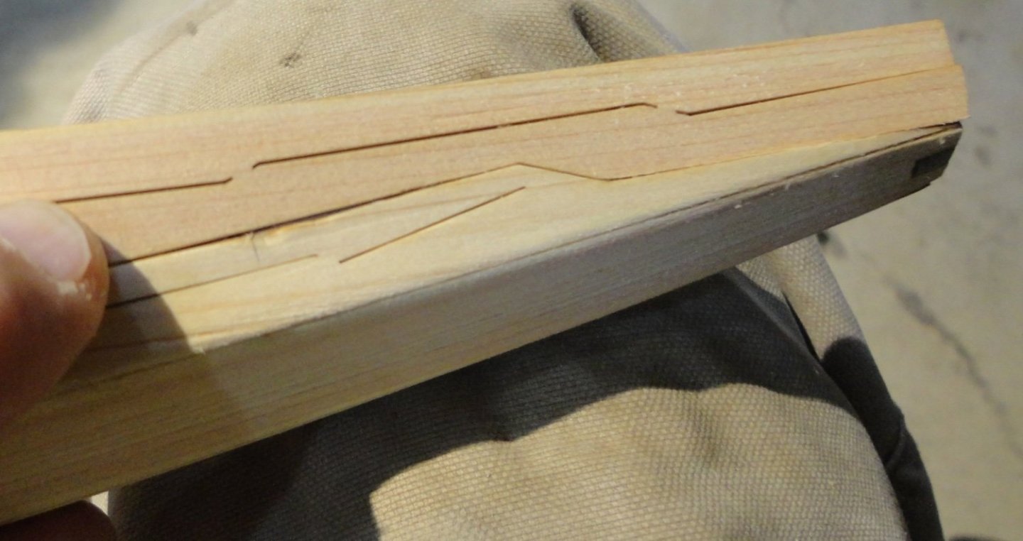
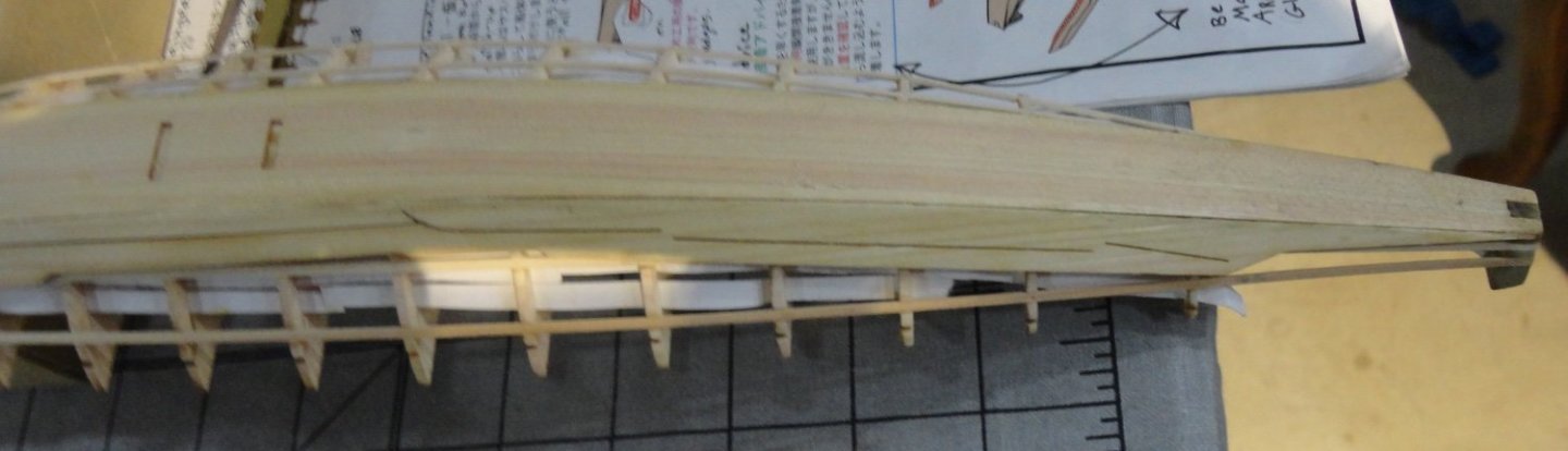
The last planks, though dry on the surface, still retain some moisture inside that might take a couple days to fully dry out. Thats OK since they can still be bend to adjust as needed. These planks needed just a little sanding/trimming of the edge angle to fit well with the planks already in place. I also found that (since they are on the wide side - having two planks conjoined) I could use my sandpaper covered hacksaw blade (bend just a little more) to give the inside of each plank a slightly concave profile to better fit to the ribs. They still need a little bending as well. I found one place where I'damaged a plank ... don't know if it was with a clamp as the planks are a softwood, or by some other mistake. I'm still fitting the last plank, so it's edge angle is not finished - but I was concerned that the damage to the mating plank would not show well on the model. Then I recalled a technique I used some time ago when building a harpsichord, and needed to adjust some of the mortices on the keys where the mortice I made to accommodate the locating pins (and allow travel also) were a little too wide. The manual suggested making a fine cut with an X-acto next to the mortice and inserting a tapered sliver of basswood (the keys were basswood) into the cut. Then the side of the mortice would move outward to reduce the width of the mortice (and then try to work the pin and adjust as needed). It's easy to remove wood, but tricky to put it back. Since I didn't want to glue a piece in and have the edges of the patch show, I tried the above method. Step 1 is to make a cautious cut into the edge of the plank. Pardon my focus, but I was holding the workpiece with one hand and the camera with the other while trying not to have the knife fall out. The next picture shows the wood slivered (tapered at the ends and bottom - made from a piece of stringer stock, part #28) just started to be pushed into the knife cut in the edge of the plank. Then I pushed (without glue) the sliver into the cut with the butt end of a round file, and then the pointy end. It did expand the plank thickness in the affected area, which will allow a little sanding later to make flush (but not so much as to expose the wood sliver. Now with a little adjustment made to both planks, it looks a lot better and should clean-up later after gluing.


- 63 replies
-
- 9
-

-
-
- Finished
- Khufus Solar Boat
- (and 1 more)
-
Ahoy Daniel ! One can see a number of approaches in the various builds in the Forum. One builder used black crayon sparingly on the edges, which did not 'soak in' at all. After decking excess seemed to clean up OK with some scraping/sanding. That having been said, I want to use the black thread method on all the joins (including the ends) the next time I plank a deck. The thread should not be too thick, and the picture you posted looks fine. My guess is that using a small wood scraper (sparingly) will not produce the fine dust that sanding can make. If sanding dust gets in the small gap between the planks, it might take s very fine brass coat brush to help get the particles out ... or with blasts of compressed air. If 'Dust Off' doesn't work, that of an air compressor should. Whatever method you want to try, doing test piece with a number of planks (they don't have to be good modeling wood) is highly recommended. You can then judge the results for yourself.
- 5 replies
-
- 2
-
-
- Polaris
- first build
- (and 1 more)
-
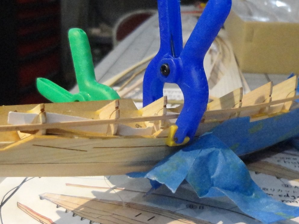
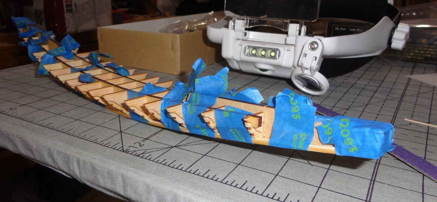
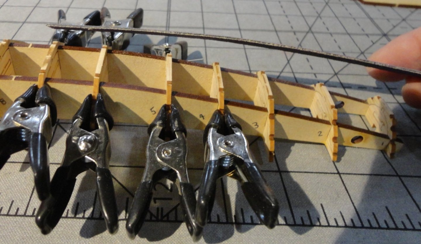
Ahoy mates ! I found that bending the middle strakes for each side was easy, and I modified the method as follows: Run hot tap water over the piece as before, then (once half-soaked) I moved the strake back and forth over the gas burner flame ... almost right on the flame (there is a danger of scorching if the wood goes dry on the surface) and it will become almost too hot to hold (but not quite) and the wood will give off steam. Then it bends easily, but I used both hands with the fingers positioned on the outside of the bend and the thumbs on the inside as a 'human mandrel'. One has to have the 'feel' of how far to push it, but the Japanese Cedar is generally compliant. Since wet wood doesn't sand very well (raises fibers like crazy), I let it dry a bit first. It fit into position like a glove and there was no adjustment needed on the angle where the edges going with the garboard strakes. Glue was applied and I kept using blue painter's tape, with clamps on one end where it needed a little more than tape. Left and right were glued and allowed to dry together. Some observations: Titebond glue (aliphatic resin) once past the 'grab' stage will go into a 'soft set' (something like 30 minutes). There is still pliability at this time, and some positional adjustments or re-clamping can be done then. A wood part can be pried off still without too much trouble to re-position after 'refreshing' with a little new glue. After 1 - 2 hours it has what I might call a medium cure, and the parts can be sanded/trimmed with care. If something slipped while setting, the isopropyl alcohol removal method (see earlier in this build) will work quickly and effectively. A 'hard cure' takes several hours. When removing blue tape, do so gradually (and at a 'low angle' to the plane of the surface) to avoid pulling up wood fibers. I use the tape for painting edges that has no more than a 'medium' stick ... other tapes with more 'stick' should be avoided. Gorilla tape is RIGHT OUT. I bent the final strakes as above and decided to tape them to the frame to set the bend. A view of the interior as the planks dry. Once dry I removed the tape (except in the middle so the planks would not fall off), and they had very little spring-back. This may be because I worked them good per the 'wet wood over flame' method described above. They were over bent a little so allow for spring-back. Obviously there is some, but noting to fret over. I have to get into scrubs for an evening shift at the hospital, so I'll post more on planking later. Johnny

- 63 replies
-
- 8
-
-
- Finished
- Khufus Solar Boat
- (and 1 more)
-
Rob has offered some good advice, which is pasted from an earlier post in this log: "I just wanted to help those, thinking, or beginning rigging on their own models. 3 things I want to leave you....1: Use the appropriate size cable for your rigging (Smaller is better). 2: Use the appropriate color, Greyish tan is best, (deadeye lanyards are NOT running rigging...stop using tan cord) 3: Rig as much as you are comfortable with(but if you put that much effort into your hull build...why stop there, challenge yourself, you'll be a better modeler because of it)." In perusing a number of logs, the ones who make use of what can be considered 'miniature rope' for their rigging (made on a mini rope-walk such as Chuck's rope rocket, or purchased from a vendor using similar techniques) look the best. There is very little rigging 'fuzz' - which shows up on close shots, and must be visible on a close examination of the model. Some kit rope isn't too bad and can be treated to reduce 'fuzz', but given the effort (and cost) that goes into a build, why not make the most of rigging opportunities - as rigging is often 'half the model'.
- 3,560 replies
-
- 2
-
-
- clipper
- hull model
- (and 2 more)
-
Ahoy Chris! 'Had to do a double-take on certain metal ship models offered by the Piececool brand, since I have a couple by Metal Earth (Iconix) kits that are 'ringers' for the photos in the link. So I did some research and found that Piececool and Metal Earth are different brand names for the same products engineered by Tenyo, a noted Japanese manufacturer of an eclectic variety of 'thin metal' assembly models (ships are a small subset) ... there is no piracy involved. Metal Earth is intended for U.S. sales, whereas Piececool is marketed in China - same ship kits. You can get either legitimately on-line, and Amazon carries some of the both brand's product line. The quality level (according to a metal molders' review) sets the standard, whereas the ARE some 'other' brand names that are copy-cats with lower quality (e.g. thinner metal that breaks easier).
-
There is a brief build log of a small-scale metal USS Arizona I posted ... it was a 'break' from a much longer project of a wooden model. The the metal medium may be of interest to some (like me) who would never attempt metalwork if it were not in kit form - thus fully engineered.
-
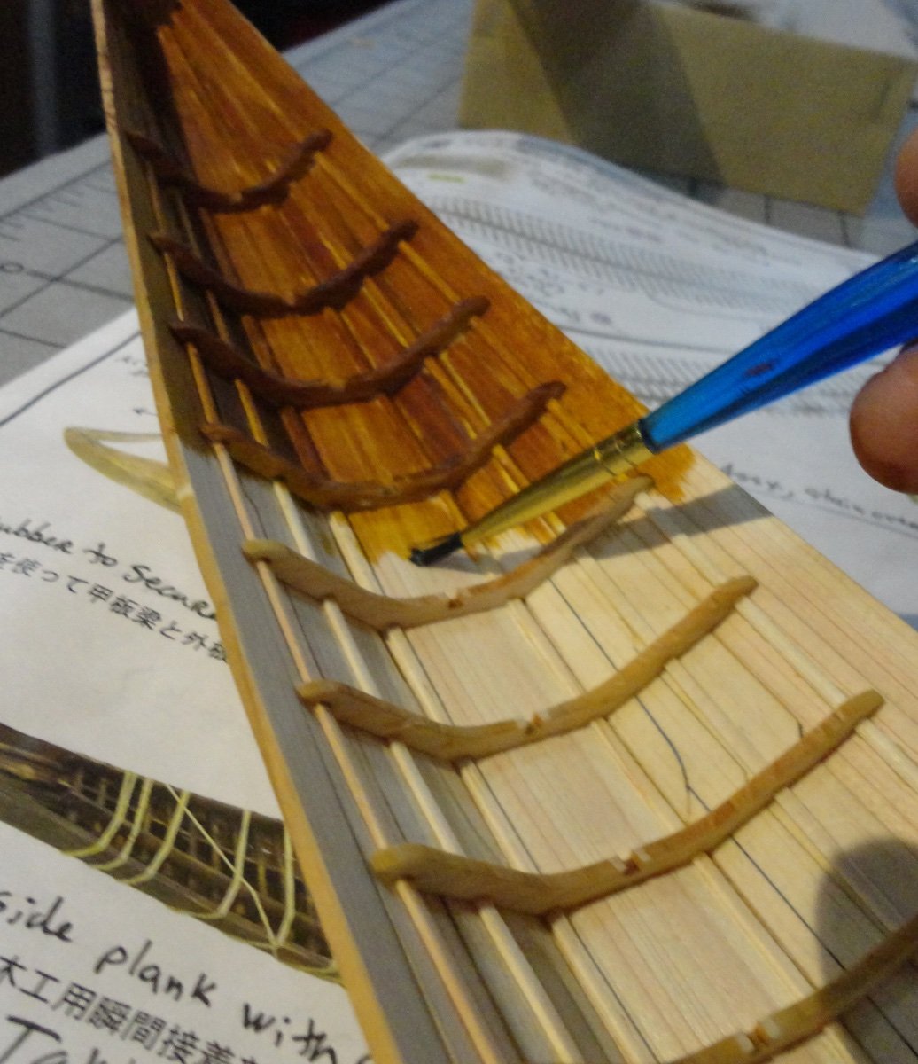
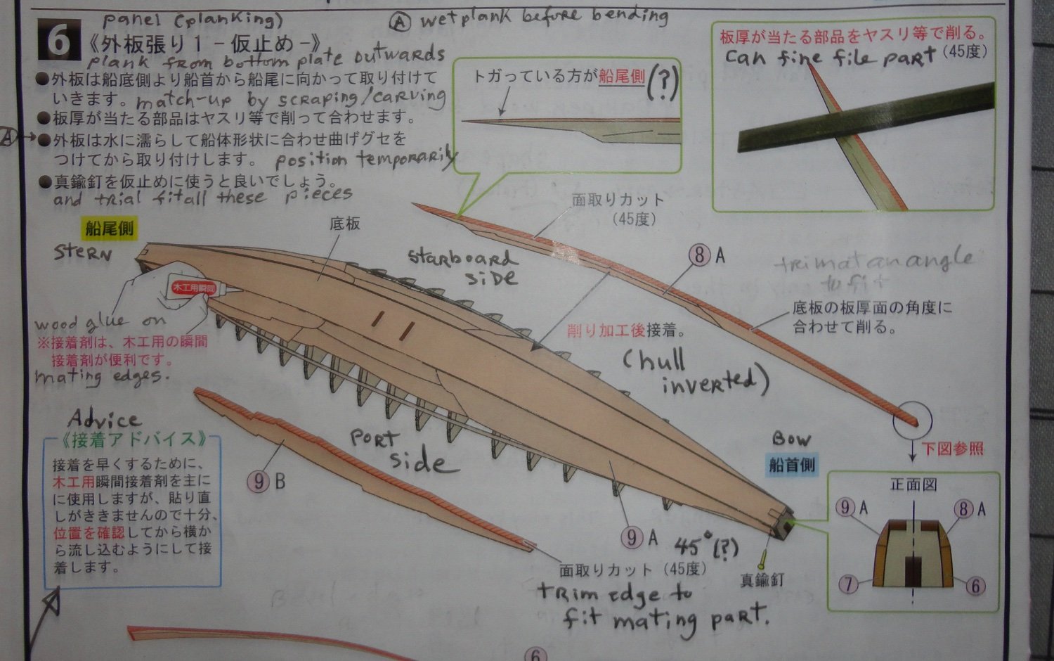
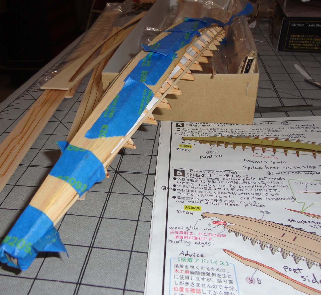
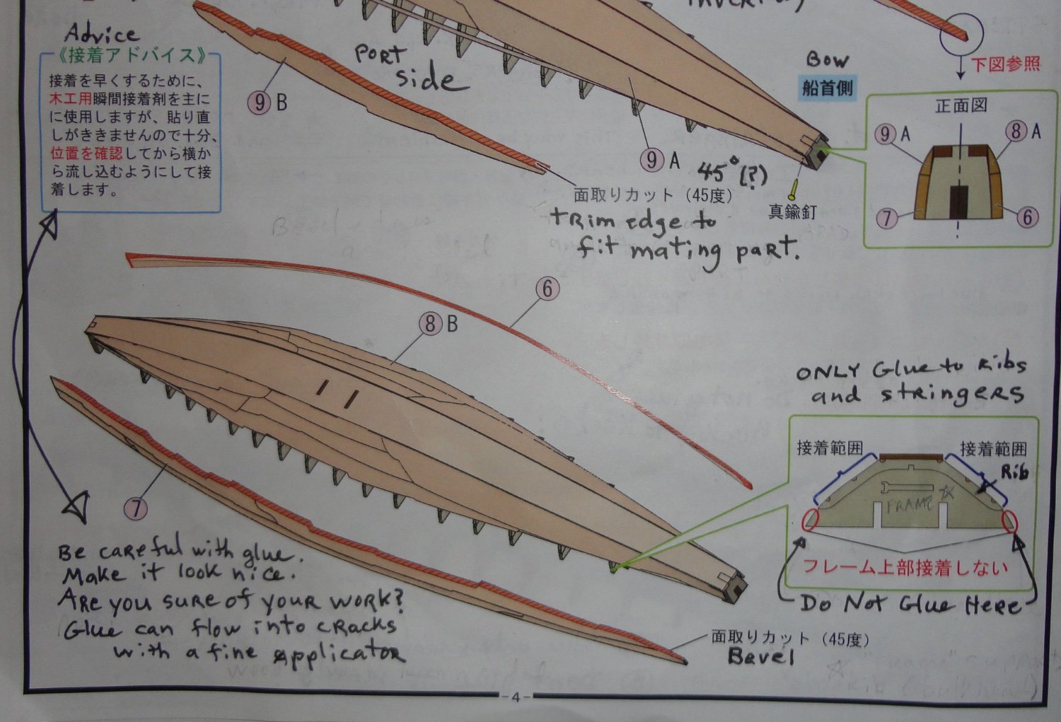
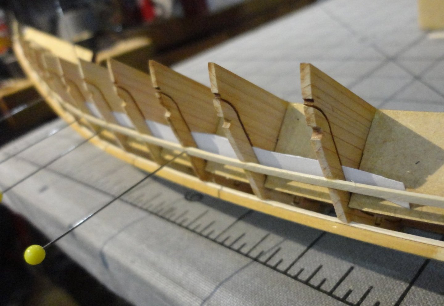
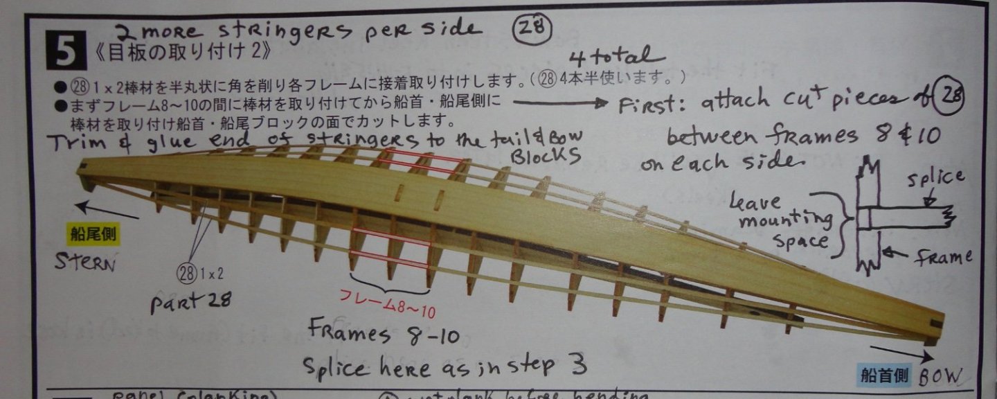
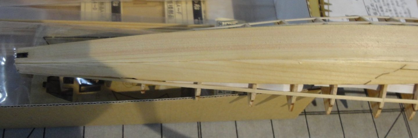
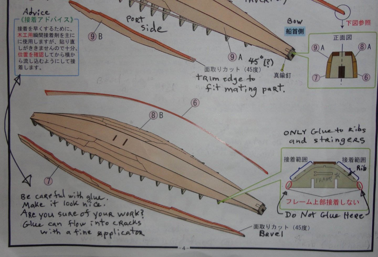
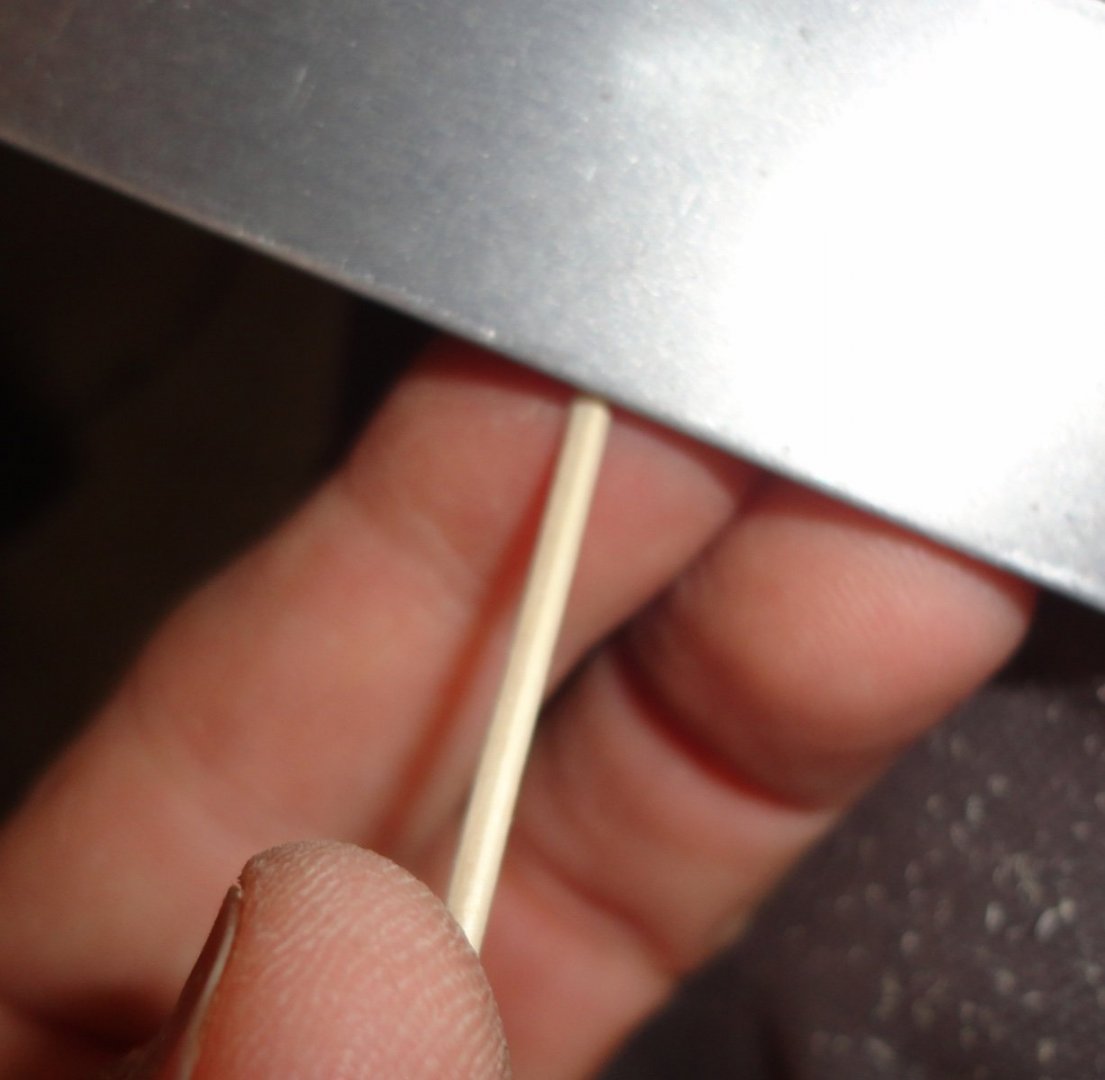
'Been a couple days since my last post, but I've had progress in between many other chores. FIRST, the isopropanol titebond softener WORKED like a charm! I used 90% iso (as opposed to the more common 70% found all over). It didn't take long to work and I was able to get the mis-glued end block off, clean off softened glue residue, let dry then re-glue (after a little filing and trimming) where it should be. I also used a 'dremel' (actually a foot control flex shaft Chicago Tool found at Harbor Freight) to cut two places for the side stringers to go ... seemed a good idea that actually worked out. Below is a picture of the first side stringer in place, and I used a few pins (with care) to retain. 'Reminds me of building balsa model planes as a kid. Note also that I put strips of filing card stock between the ribs and the frames to fill the void where the ribs were laser cut. A closer look at the rib gaps filled by paper strips. Below is a pic of the second stringer installed (with pins) ... and great care was taken not to push the pin in any more than needed due to the danger of cracking the ribs. I had to fair the stringers with the handy hacksaw blade equipped with sandpaper. Then everything was ready to consider installing what amounts to the garboard planks. I cut the aforementioned side rails to consider widening the bottom plank ... but then discovered some real disadvantages to that. A.) The side planks in the kit are designed to be mitered to the bottom plank. So if they are to be installed on TOP of a widened bottom plank, then the side planking would end up higher by the thickness of the bottom plank. I couldn't trim that off the garboard planks due to the configuration of laser cuts on that plank to conform to all the odd-shaped component of the original ship. Trimming the topmost plank later would also present problems. B.) The angle between the bottom plank and the garboard planks amidships are at a more acute angle than at bow and stern. This angle would have to be matched on the outboard edge of the garboard planks, so any over-cutting would result in gapping hard to fix. Building per kit layout is done by angling the garboard planks on the inboard side a little at a time, which CLOSES the gap between them and the bottom plank gradually. The original ship is profiled on the exterior, so I expect to use a scraper to round things up a bit. This can also expose some of the edge of the bottom plank as seen on the original - which should close and residual gap between the garboard planks and the bottom plank. The original had a flat bottom, and I expect that was to go into shallow water and be able to draw up to a bank on the Nile. Below is step 5 (now done), and again - I didn't just splice between frames 8 & 10, but used stock starting at one end (then the other on the next stringer) and splicing where convenient 3 frames from the other end in order to conserve stock. So I soaked the starboard garboard plank under a hot tap water, then discovered that our tea kettle had corroded in two spot in the bottom and leaked. Water was boiled in a frying pan and ladled over the plank until pliable. I even held the wet plank over the gas stove burner (by about 3 inches) and moved the piece back and forth until it was very pliable. Using both hands, I formed the piece ... a compound curve that has to twist near the ends. I held it up the the frame to judge the bending, then started to trim from the bow end as shown on the instructions for step 6. This turned out to be a sub-optimal way, as I was working down from one end trying make an acute cut at the very bow (per the picture in the instructions. Top half of step 6 instructions. They must presume a certain level of experience, confidence and creativity on the part of the modeler. Easier said than done. I had to trim some to get close to where I thought I should be, then trial fit. I was afraid of cutting too much with the X-acto, so resorted to the sandpaper covered hacksaw blade. I also had to let the wood dry out some - but not totally so I could still bend it. I worked on it for over an hour - trimming/sanding, fitting, bending, re-sanding ... then fudging some. I even resorted to bending the bow end some with my teeth - and also accomplishing some of the 'twist' near both ends with my mouth and teeth. It was a real bugger to do, and the most difficult plank I've ever had to fit ... so this plank is not at 'beginner' level. The 'pointy' end at the stern presented its own problems. I now realize that I should have started beveling the plank amidships, then worked out toward the ends. This I will do on the port garboard plank. I marked the extent of the areas that needed glue applied on the ribs, stringers and bottom plank. Then the garboard plank was located, taped amidships and then out to both ends. I let the glue dry a couple hours, then removed the tape to see some gapping. Wood glue was put into the gaps, then the excess wiped away. I applied saliva by licking the seam (I would do anything for love ... but I WON'T do that) and spitting out any residual glue. Since the angle at the edge of the garboard plank comes to a point (supposedly to make a mitre with the bottom plank), I used the smooth round handle of a round file to 'burnish' the softened edge of the garboard over towards the bottom plank. This drove out some of the glue, which was wiped up, then more burnishing. As the glue started to 'grab' the gap remained closed. Near the bow and stern, the plank ended up slightly shifted vertically from the bottom edge of under plank, but this will be modeled/scraped later as needed. As I said, this entire process was a pain, but in the two photos below, one can see that the join ended up pretty good ... but then I've done planking before, as well as a lot of other wood working and crafting. How a beginner would fair with the garboard planks on Khufu's ship is another matter. There is a little gapping going towards the stern, but there is also enough material to scrape away later that the gap will disappear. Note also the laser cut on the garboard plank that represents the odd-shaped original planking. Once all the planking is done and shaped to my satisfaction, I plan to engrave a 'connection' on the surface of the plank where there had to be disconnects in the laser cutting to prevent those pieces from falling apart. Below is the bottom half of the step 6 instructions. I note the translation of the "advice" ... 'Make it look nice.' 'Are you sure of your work?' I also note that they show a brad used, which I did not do. I used tape, which did pretty well - but the very end of the garboard at the bow wasn't quite in contact (probably why the show a brad) - so I used a pinch clamp to hold it fast until the glue set well.


- 63 replies
-
- 7
-
-
- Finished
- Khufus Solar Boat
- (and 1 more)
-
A few scale figures doing stuff?
-
Dremel rotary tool?
Snug Harbor Johnny replied to Mark m's topic in Modeling tools and Workshop Equipment
My brother claimed the old-fashioned belt driven dental drill with foot control from my Dad's estate. (For basement stuff it was first come, first dibs.) The big advantages to it was the head having a 90 degree angle, and the decent torque at low speeds. The trick to get used to is manipulating the mechanical 'arms' connected to the drive head. I have the low priced flex shaft unit sold by Harbor Freight, and it has been useful. I like the foot control and the torque is pretty good at low speeds. -
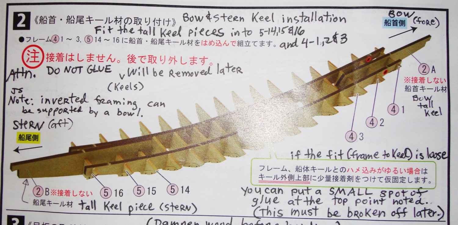
'Great idea, Ron ... Now that you've mentioned it, the iso glue softener tip appears now and then in posts - but I'd forgotten all about it. Aha, this is advantage of wood glue over epoxy or CA. I'm taking time to fair the other stringer attachment points by laying the end of the round file (actually, an oval file would be better) OVER the rib with a stringer in place to see if there is a gap. Then a couple more file strokes are made before the next test. When the fit is right and there is no gapping, I can mark a small pencil 'x' at that point. Where I put pencil marks on the build is at points that will not show. Another idea that came to me was to use a file to make cut-outs for the stringers (two per side) on the sides of the end blocks. That seems better for pre-planking prep. Speaking of planking, I was looking ahead to how the first side plank goes in according to the instructions ... and I see a certain difficulty not consistent with a 'beginner' level kit. They show the bottom plank trimmed flush with the end block, and the first plank beginning with a HUGE angle pared on the inboard side. But that angle must then be reduced gradually to about a 45 degree angle - but that requires that the bottom plank go from being flush with the end block to having about a 45 degree angle. Both planks have to have a 'spiral' bevel that matches well - a hard feat to do. Yet this is NOT the condition of the planks on the original. Museum photos show the bottom plank with an exposed side thickness down the entire length ! These were thick boards (what, something like 4" ?) with internal tenons, and the first planks were fitted to the top inside edge of the bottom planking from bow to stern. The kit would have been better designed with a WIDER bottom board that one could just fit the edge of the first plank to the bottom board - angling the edge of the first plank only. Once done, any overhang could be trimmed off the outer edge of the bottom board. This would have made more sense AND be closer to the original. What to do? I could glue a strip of material to the edge of the bottom plank to widen the entire plank, then install the first side plank as above. A straight strip will have to bend in two axis ... but since I have the board used to laser cut the bottom plank, a french curve can guide a knife to cut around the original perimeter where the bottom plank came out of it's mother board. That will have the exact curve along the width of the bottom board, so it will only need bending in one direction fore and aft. The wood provided seems quite pliant in thin strips, so I'm going to try this approach ... a minor 'kit bust', and something future builders may do to lessen the headache of doing it according to the kit instruction, such as they are. As noted in my review of the unbuilt kit (reviews section of the forum), I used Google Translate and held a cellphone over the Japanese text to see what the app would display on the camera screen. The 'translation' kept changing, and some really odd things would come up in succession ('wish I'd written some of them down), but some of the translation was consistent. Something that made sense as 'Do not glue. Will be removed later.' might morph into, 'No I won't do it. Come to my house later.' or 'She can't assimilate. Only take her later.' Go figure.
- 63 replies
-
- 6
-
-
- Finished
- Khufus Solar Boat
- (and 1 more)
-
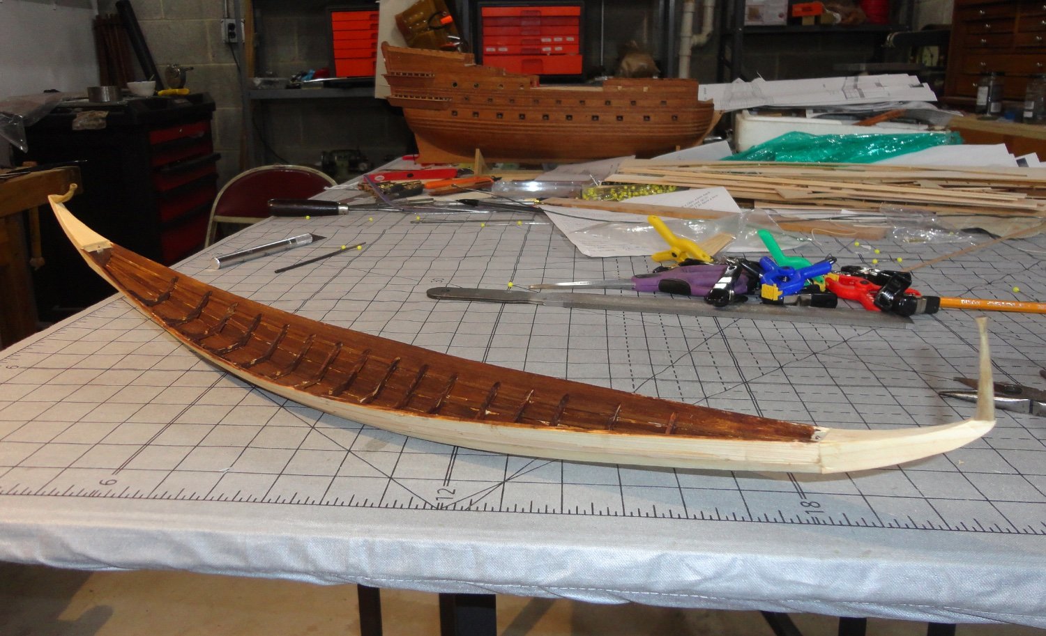
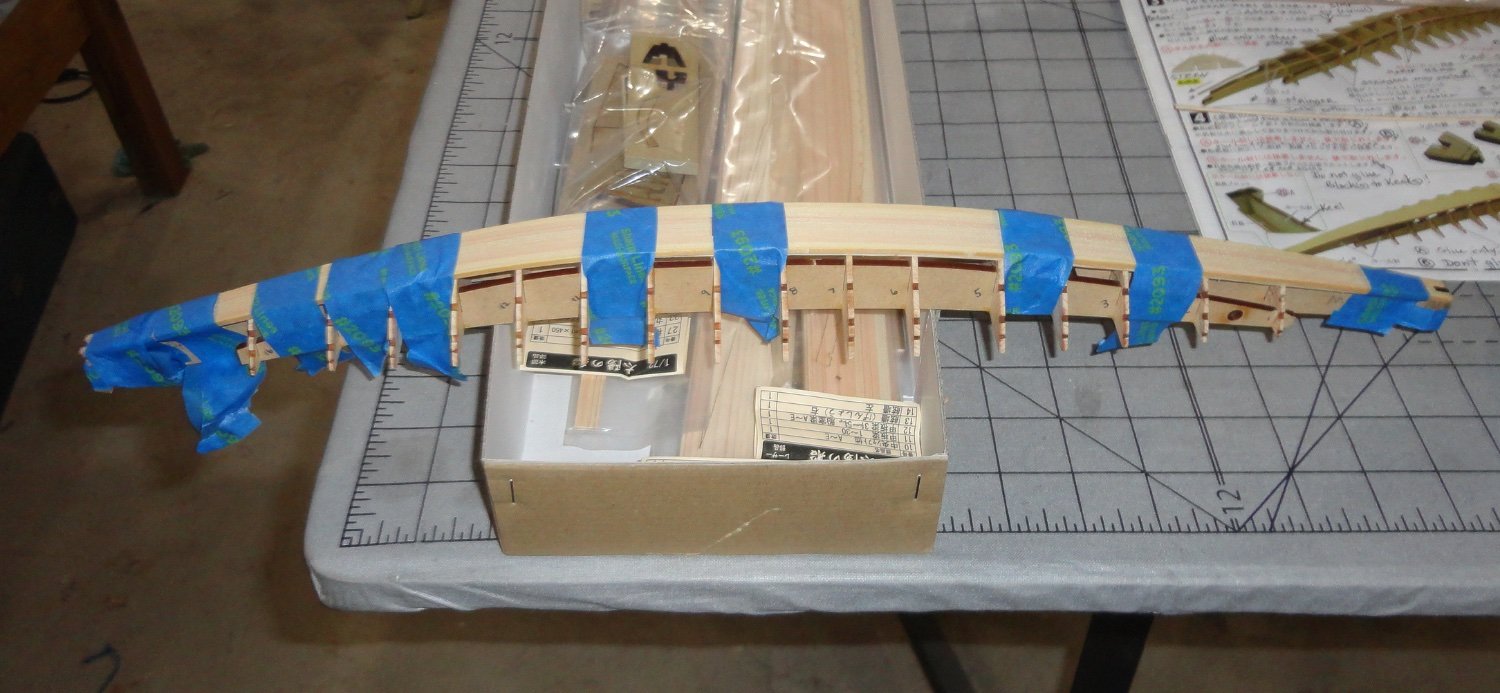
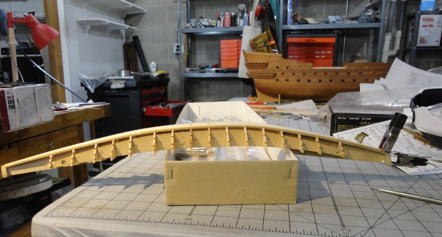
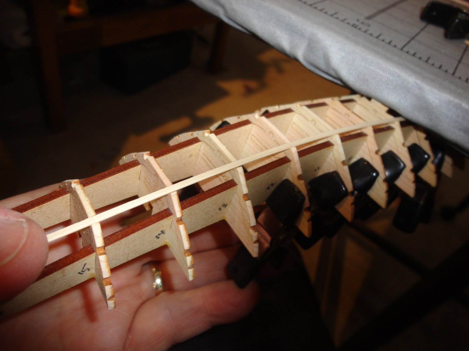
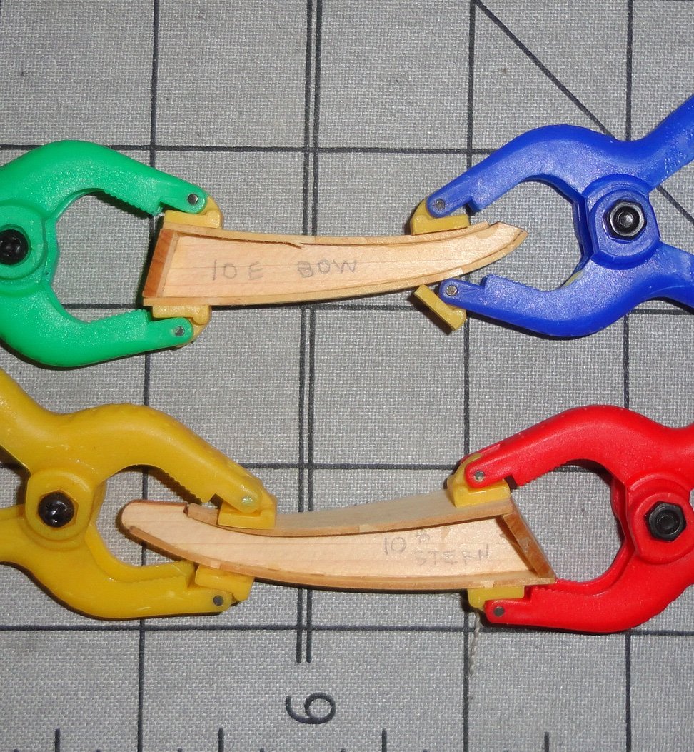
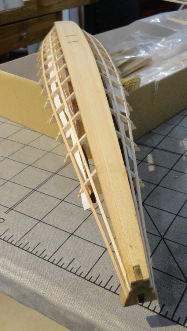
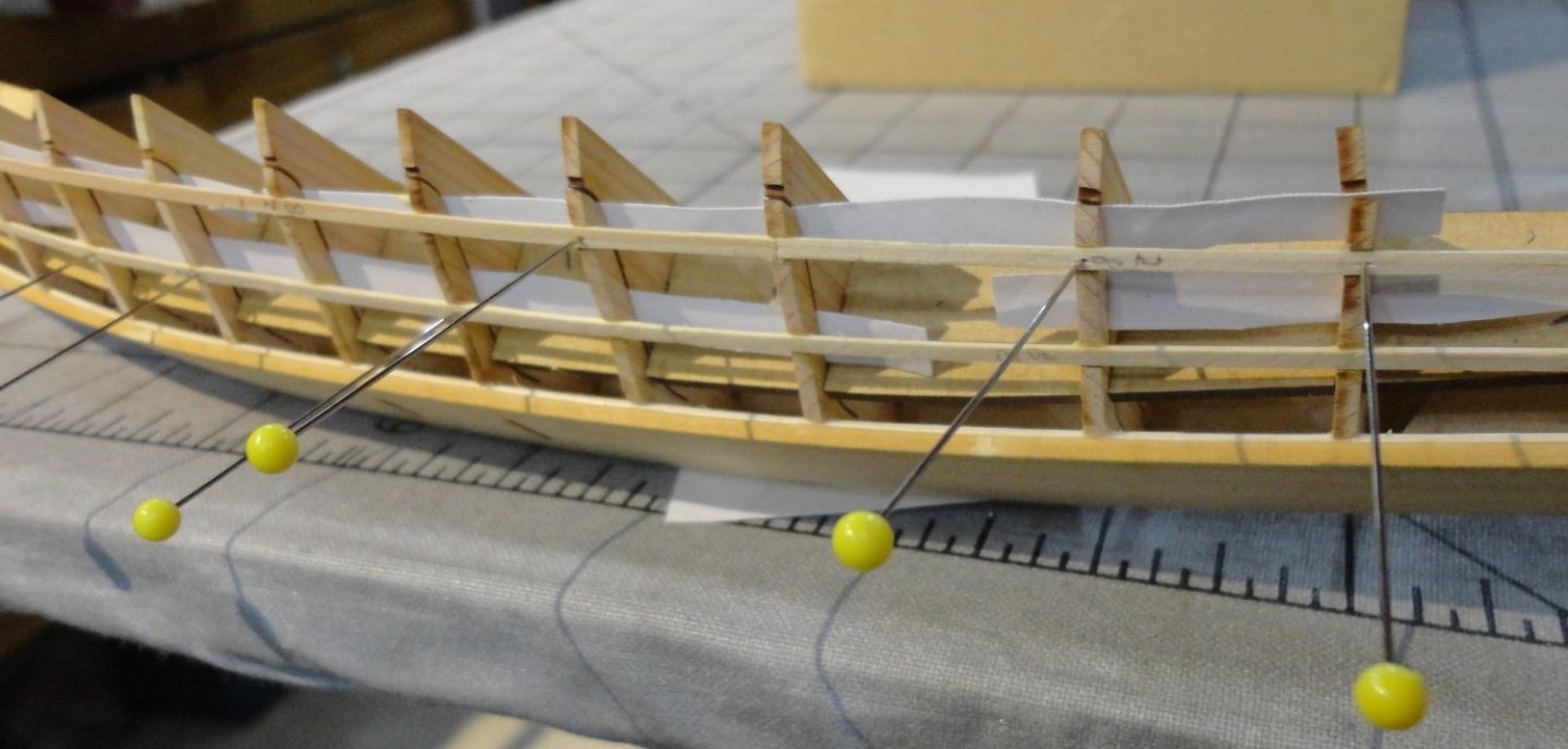
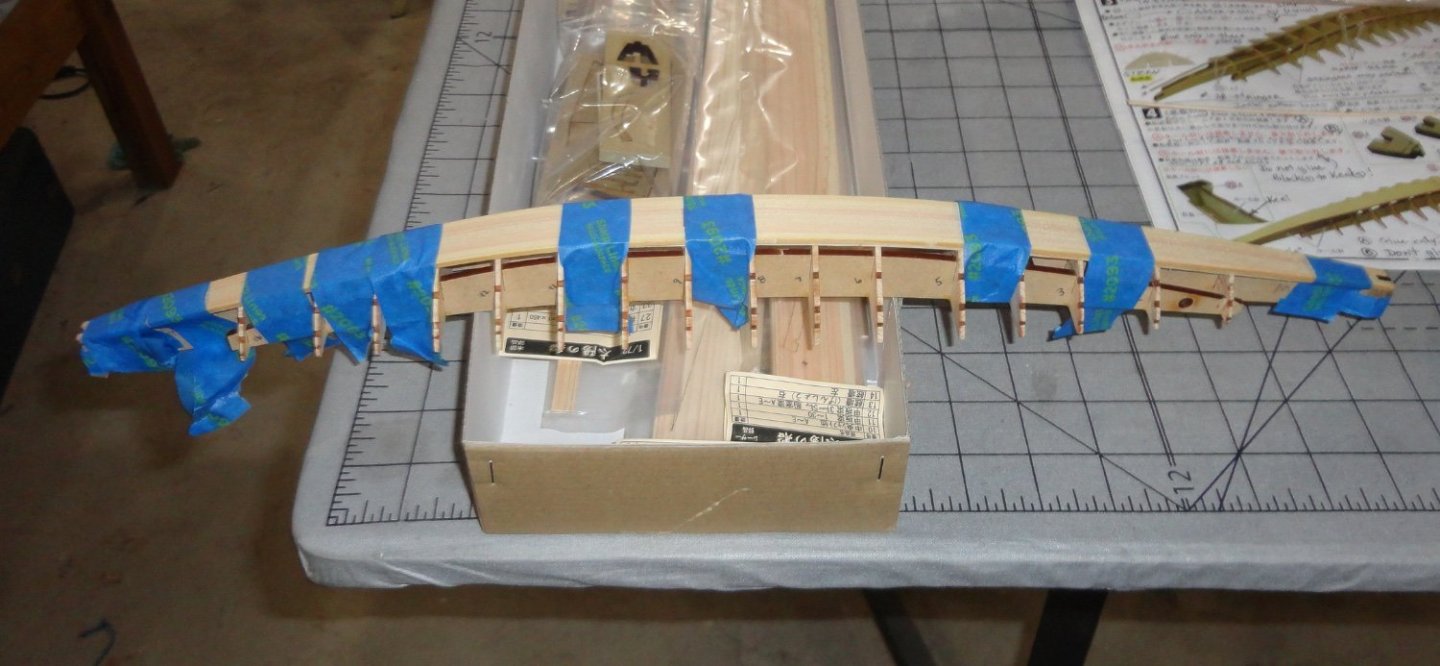
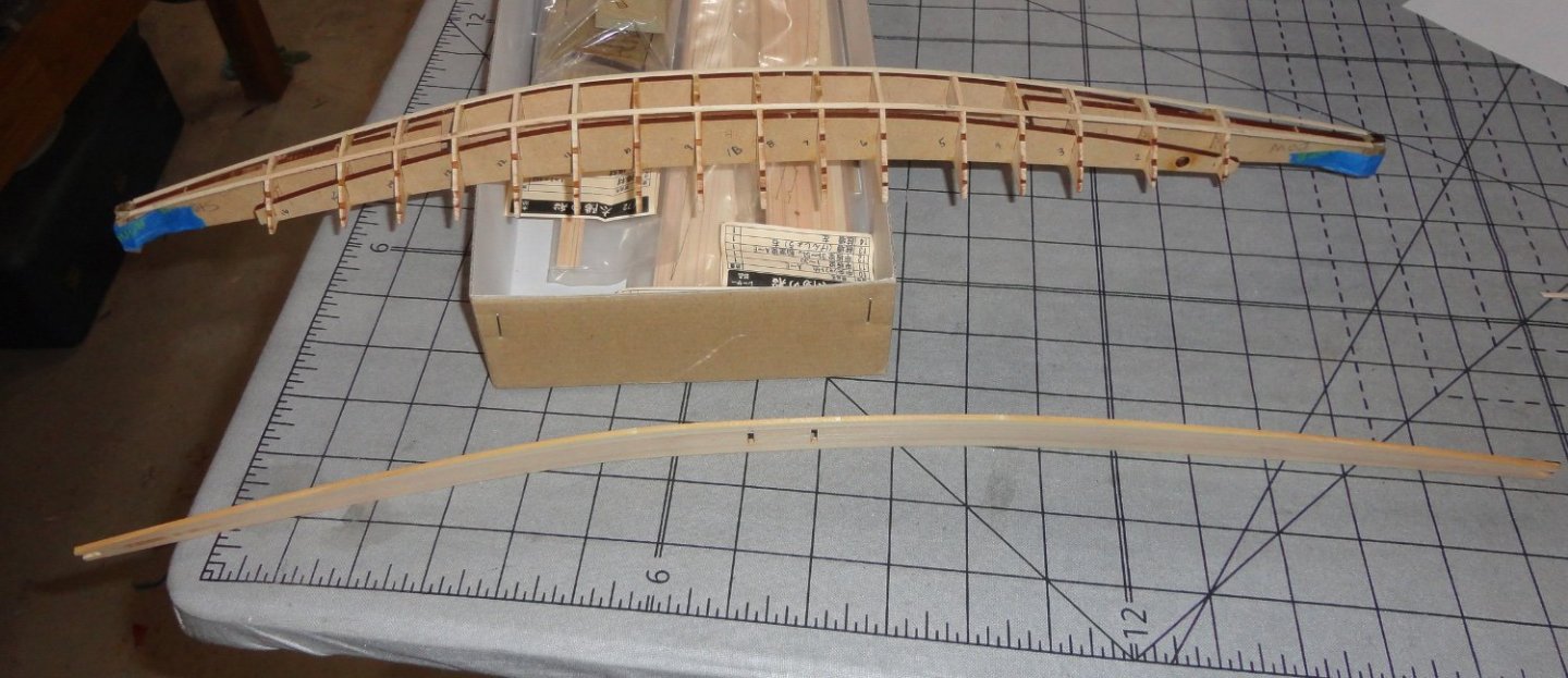
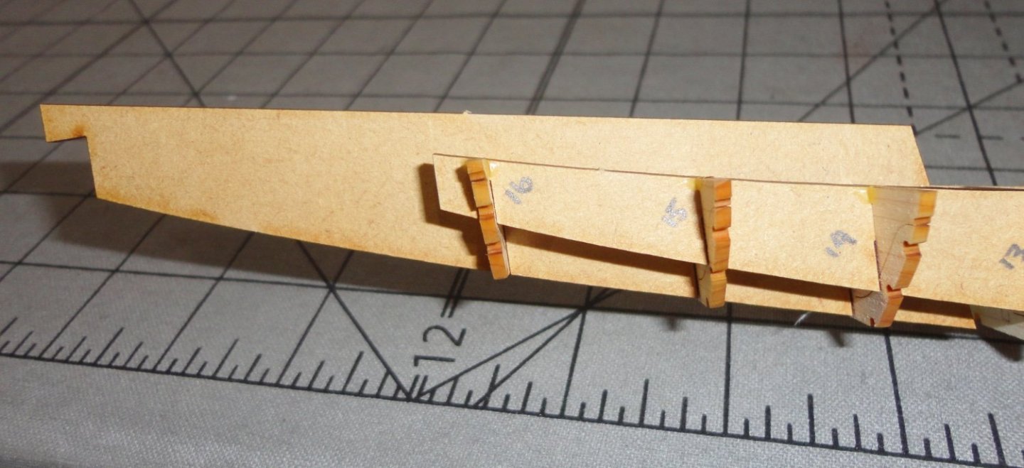
So I've progressed a little further on the Kufu ship ... I forgot to put the scale in the title, which the kit claims is 1:72. The original Royal Yacht was 145 feet in length, so the model should be marginally over 2' long (haven't bothered to measure the full size drawing yet). BTW, the drawing came in TWO pieces, which I'll have to join with tape to make a single page ... a minor inconvenience. I decided to pre-bend the bottom plank but running some hot tap water over both sides, then moving the parts of the plank I wanted to bend over a steaming tea kettle. Sorry, but since I had to use both hands to do this I couldn't take a picture. I try not to annoy the Admiral with my hobbies, and since I did this at about 11PM so the piece could dry by morning - I did not want to disturb her slumber ... duh. Anyway, the kettle did the trick and I found the heated plank easy to flex (with care) and it 'took' a pretty good approximate bend. Then I used the frame assembly as a 'caul', and secured the moist plank to the frame with strips of blue painter's tape (folding the ends over on themselves before using so it would be easier to un-tape later). This blue tape has enough 'grab' top clamp pretty good, but the sticky side is not aggressive enough to pull fibers from the wood when un-taping. In the morning before running off for per-diem work, I un-taped the plank and there was only a little spring-back. In theory, a bending caul with a slightly greater curve than needed will produce a dried piece that will spring back to about the right shape - but this would have been too much trouble and the bent plank coming off the frame was plenty close enough. I'd recommend pre-bending BEFORE doing the trial fitting shown in the previous post, since this will stress the part less and prevent that 'white finger' effect when one has to squeeze hard on something. There are other ways of bending planks (like a hot mandrel, or a heated piece rubbed against a curved mandrel) - whatever is preferred. Then I glued on the first two stringers - noting that the kit instructions to only put in a splice between frames 8 & 10 is superfluous. It seemed wasteful of stock, and I have no idea how far that stock will have to go in other places in the build - nor do I know (at this point) whether the mfg. is 'stingy' with provided stock (as some are reported to be) and only giving barely enough to accomplish the build (which presumes that one does not make mistakes or break a couple pieces). So the part #28 (1 x2 mm cedar) that was scraped to an approximate 'oval' on one side only (I marked with pencil '28' on the flat side so not to get it wrong later) was glued (starting at the stern block) most of the way along the ribs, and only stopped three ribs short of the bow - where I cut it carefully to take up half of the cut-out in the rib. Then I measured and glued a piece to finish going out to the bow block. I used 'thickened' titebond applied with a dab in each cutout (dental tool used for neatness). This stock did not require moistening, since it bent readily and offered little resistance to the gradual bend required. Surprisingly, it stuck right to the congealing glue and did not require clamping ... sweet. But look closely in the photo below. Some of the cut outs were not filed perfectly, and the stringer 'stands proud' just a bit from the ribs. This will affect the gluing of the bottom plank as will be seen shortly. Better trial fitting of the stringers, a little better fairing after the stringers were glued and trial fitting the bottom plank AFTER gluing/fairing the stringers is advised. Everything is related on this build, and there are things I didn't 'think ahead' on. When the glue was cured, there was some additional faring of the stringers, but I did not want to thin them too much because they are thin enough to begin with. The attachment to each rib does help reinforce the stringers, but they are still delicate and subject to breakage if pushed. Below is a photo of the pre-bent bottom plank next to the frame assembly with ether first two stringers. Note that the end blocks are retained by blue tape at this stage. It is another 'catch-22' situation. If they are not in place when the bottom plank is glued, any mis-alignment (yaw) due to a slight looseness of the location tabs amidships will result in lateral displacement of the ends of the plank - a situation that will be hard to fix once the glue dries. The taped end blocks locate the plank properly fore-and-aft ... but there is a risk that they will 'shift' outward slightly (tape flexure), so if glued (as I ended up doing) to the bottom plank - corrective sanding would later have to be done. My solution (in hindsight) would be to use the blocks here as a guide but glue the plank to all the ribs and stringer EXCEPT the final fore and aft stringer pieces and the blocks. Once the glue is dry, everything can be untaped and the blocks (and ends of the stringers) can be adjusted/trimmed as needed THEN glued. BTW, note that I'm using the kit box to support the frame ... the quickest and easiest thing to do. Yeah, I know a few of the capitalized acronyms like; LOL, ROFL, BTW, FWIW, PITA, etc. ... but I asked several people what IDK meant - and nobody seemed to know. OK, so below is everything glued and taped-up to dry. So the bad news was that the blocks had shifted, but the good news was that the plank lifted slightly from the stern block (tape 'give' - a clamp would have held more firmly) so I could remove it, scrape and adjust for perfect fit and regale with clamps as seen below. I include another view of this, with my beloved Wasa in the background. Yeah, I will resume work on it over thew Winter, and even then, maybe having two project underway will permit work done on one while glue is curing on the other. A side benefit of this hobby is that I like to think about different ways I might do something, look for other ways used in other builds - then weight the advantages/disadvantages of the various approaches, all while doing something else like gardening, chores, or while pushing drugs as a per-diem pharmacy tech at our local hospital. There are many miles to go every shift with a cart full of medications, thus I'm a legal 'drug-pusher'. Other techs tend to use hand baskets, but I tell them that I use the cart even for light loads because it looks better than using a walker. The last photo in this post shows a close-up of the mis-match between the bottom plank and the bow block. That was the OTHER bad news that the bow block had shifted AND the glue bonded the parts. Here is where the stringers that 'stood above' the ribs (and not fully faired since I did not want to thin them excessively) came back to haunt me. They cause the bottom plank to bend over a slightly longer curve, and therefore did NOT fully engage the bow block. OK, I can correct this later once planking is complete by sanding the face of the bow block as needed. Hopefully, Forum members who'd like to build this kit can benefit from all the observations I'm making in this build log. Certainly, as a presumed 'beginner kit', actual beginners will benefit from the expansion of what translates from the kit instructions. Another story about a good news - bad news situation. It was on an old US navy whale boat friends of mine converted (back in the 70s) into an ersatz 'Viking ship' (more like a small Knarr). There were five oars to a side, and I was one of the rowers on a weekend excursion ... yes, we all were wearing our best attempts at Viking garb, with wooden shield hung on the gunwales and a variety of weapons available on board. The wind was not with us, so we were rowing hard. The leader manning the steer board (mounted, obviously, on the starboard side) said, "I have some good news and some bad news." I shouted, "What's the good news?" He answered, "A round of mead for all the crew!" (Cheers from all.) Then someone else yelled, "What's the bad news?" The answer? "the Captain want's to go water skiing !" ... a true story ... Johnny

- 63 replies
-
- 6
-
-
- Finished
- Khufus Solar Boat
- (and 1 more)
-
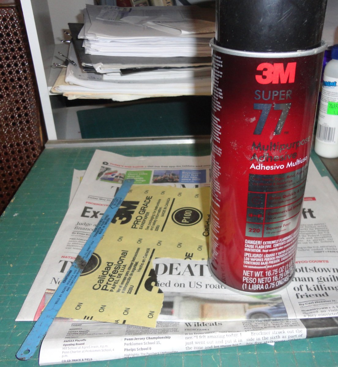
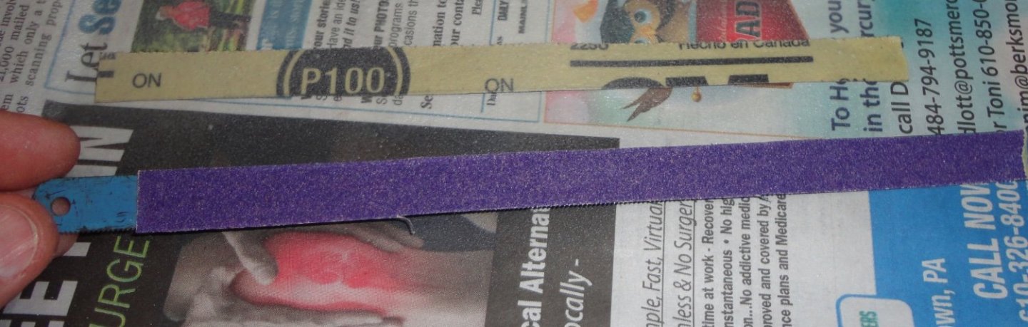
The advantages to gluing sandpaper to a hacksaw blade are: a.) It is a longer tool than the fingernail file, and can be bent into whatever curve (unless extreme) is needed to fair over a longer distance. b.) the blade is much harder to 'kink' than a foam core fingernail file. Of course, the files can be handy in many circumstances and come relatively cheaply in packs. The other 'tip' in my build is the use of 'thickened' carpenter's glue (by leaving the top off the bottle for a few days - my absent mindedness produced something useful in this instance). It 'grabs' quicker and dries faster.
- 63 replies
-
- 4
-

-
-
- Finished
- Khufus Solar Boat
- (and 1 more)
-
'Seems the thin plastic of the cathead whiskers and the martingale are easily subject to breakage. Maybe thats why they've been replaced by metal in other builds. Obviously, ship models are delicate by their nature and are easy to damage. But some parts are more easy to break than others. When done, a protective case makes sense - as dust accumulation is the long-term enemy of any model.
- 481 replies
-
- 2
-
-
- Cutty Sark
- Revell
- (and 2 more)
-
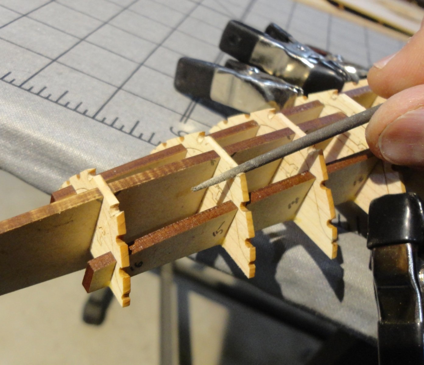
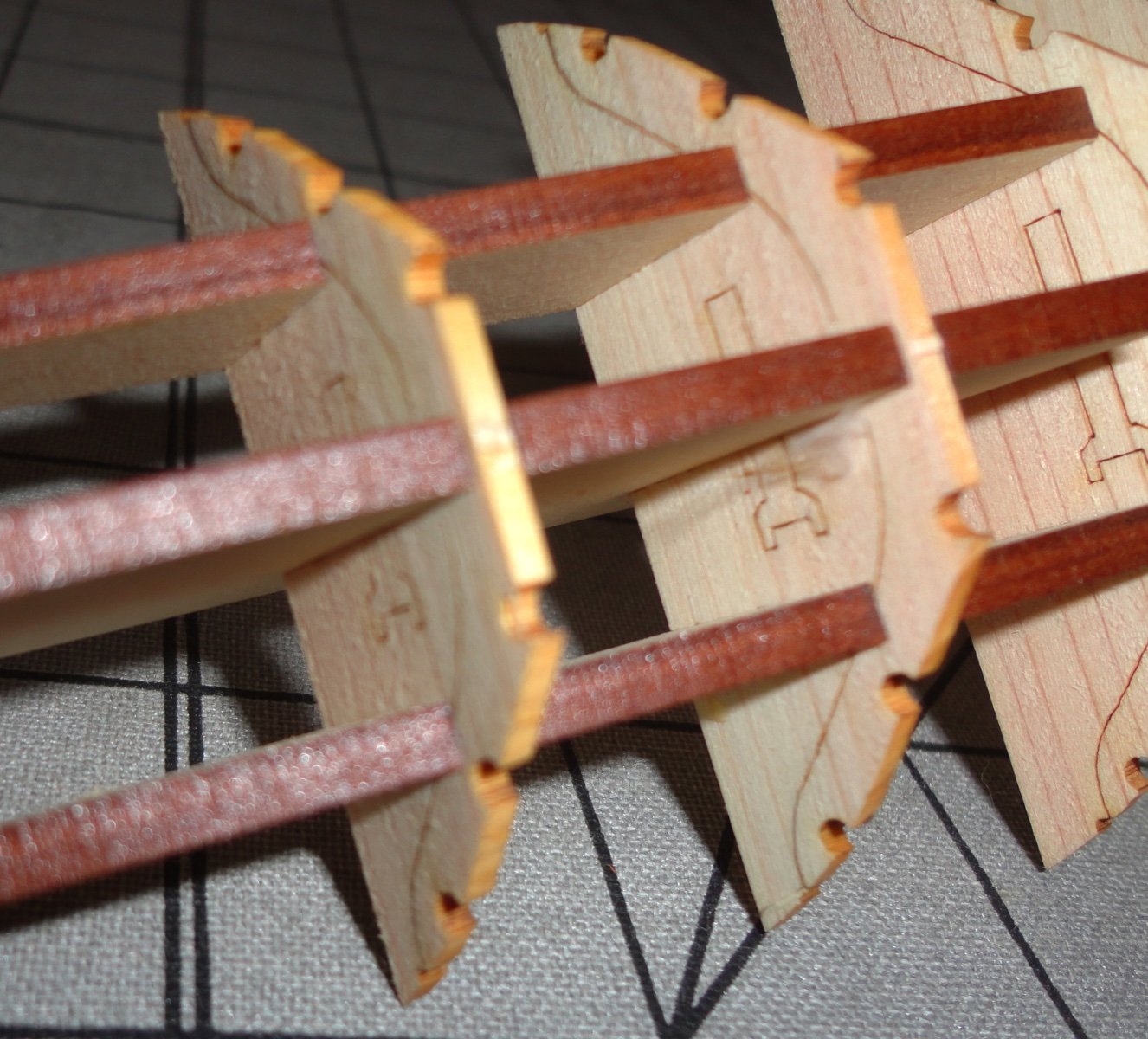
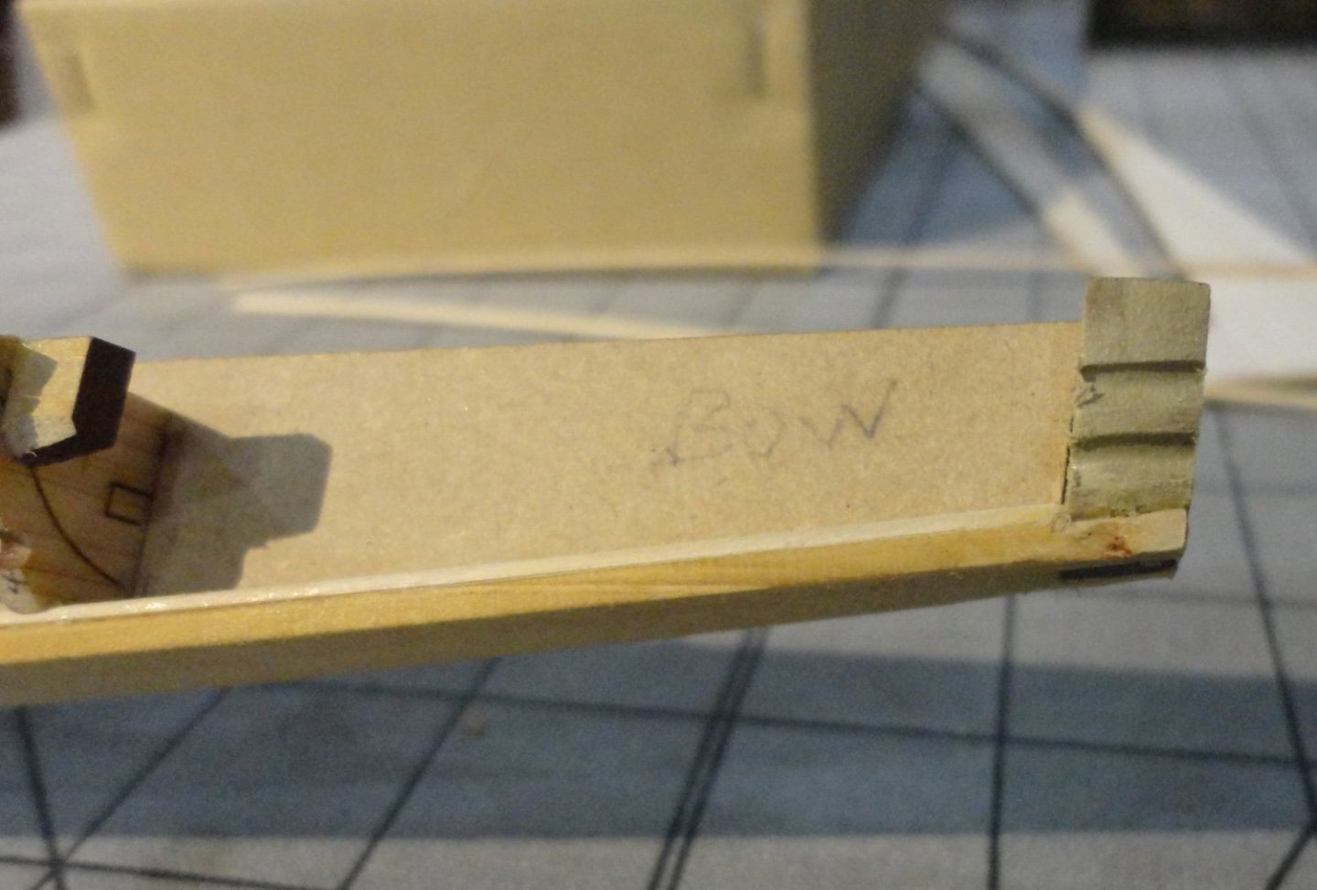
I mentioned that the ribs needed fairing, and thought how to proceed. Knife cutting is risky, as is Dremel sanding. A flat (wood) backer for sandpaper doesn't produce a curve (true for fairing any hull), so a flexible backer is desired. Then I thought to glue sandpaper onto a hacksaw blade. Out of a hacksaw, they are bendable to a fair degree and will 'hold' a curve - yet still have 'flex'. OK, one should grind the kerf off the cutting edge, but I was in a hurry to try the idea and figured the thickness of sandpaper on both sides of the blade would be thicker than the wavy teeth on the blade. I chose 100 grit 3M no-slip paper and spray construction adhesive that provides a good grip quickly and is fast setting. I traced the edge of the blade and cut strips of sand paper with scissors (a good way to dull them, so a utility knife over a cutting surface (cutting the back side of the sand paper) is better. Yeah, I know - do as I say, not as I do. The 100 grit paper turned out to be a little too aggressive - 120 grit would have been better, but too fine will take longer. Since there ribs are almost laser cut free of the frame (bulkhead), I almost broke one off - so the fix was to put temporary clamps to stabilize the ribs while working. You can see the nice curve the sandpapered hacksaw blade was bent to. And EASY pressure (very light) did the job for the bottom of the ribs. Of course, the semicircular cut outs for the stringers will need some fairing. Below, a tapered round file was used to work in the cut outs. Later, the clamps were repositioned and the sides of the ribs were faired (adjusting the bend of the hacksaw blade as needed). Note that the central 'keel' has been placed (no glue!) and it helps support the delicate ribs. The stock for the stringer (part #28) is listed as 1x2 (mm), and is very flexible dry ... no need to wet before bending on the gradual curves of the hull. Rounding it per the instructions made me think it would be hard to get it done evenly - and I considered looking for 3/32 round wood doweling to use instead, then trim down somewhat with a miniature plane before sanding flush. But I found that using a scraper (hook edge - and a piece of strip stock that was sheared had a natural burr that was suitable) and holding the stock worked well enough, as not much material had to be taken off ... just enough to test-fit. 2x2 stock may have been more suitable, but what is in the kit will serve - although delicate. I took a lot of time test-fitting formed stringer stock along the various routes it will take, adjusting the cut outs in the ribs a little at a time as needed. The whole affair could be slapped together without all this pre-fitting, but as mentioned before - doing these adjustments will build a beginner's skills without jumping into an HMS Victory right away. Shown is a step ahead of where I'm at - one that instructs the bow and stern end pieces (at this stage) to be shaped. I decided that it would be better to form them NOW, and test the fit with the bow and stern central keels - as well as check that their fairing works with a trial fit of bottom plank. Parts 20A and 20B are tricky rascals, as the exterior shaping is dynamically curved and not flat. 'Looked like carving was NOT the way to go ... too risky for both part and fingers, so I 'roughed' the perimeter against a fine grinding wheel (still having a sharp corner) taking care not to over grind or scorch the material. Then I used flat files to work them down and refine during trial fitting. 'Spent over an hour on each one! BTW while these parts are wood, the 'keels mentioned earlier as 'composite' are really a pressed paper product - perhaps something that might be for structural members in a large card stock model. No matter, they are used as temporary framing for the hull construction. A picture of the blocks getting ready to test fit. The hull is significantly curved, and the stern is more highly curved than the bow. When done, its all rather sexy - and there is a certain mystique about Egyptian artifacts. OK, I'm pressing things together (note the 'white thumb') then adjusting with a file between trials. Doing this right the first time will pay off with a better model as I go along. I'm considering making something to support the hull framing when upside down ... as opposed to putting it over a bowl as was suggested elsewhere. Also note: you really have to keep the bow and stern parts straight, as well as which surface of the bottom plank will be inboard. You can see some of my pencil markings here and there. The bottom plank will come up on a curve on both ends, so the slot where the end blocks will be glued at the ends of the bottom plank has to get a relief angle filed into it since the end blocks are vertical. As mentioned, there are all different angles to deal with. The block need to have a good fit (just snug but not tight) to the central keel of either end. The good fit is to assist in the assembly of the bottom plank ... but the keels have to be able to slide away later after all the planking is done. So I glued paper shims as needed (very little glue needed, and tension clamping between stock until the glue dries will keep the paper from wrinkling or expanding) to where the blocks fit the keels and made sure to test fit until the 'feel' was right. The picture below show the blocks on the keels and also the 'relief' cutout (nicks) along the keel bottoms to prevent any glue from bonding the removable keels to the hull planking. This configuration could have been programmed in the laser cutting, but that is a detail that got past the designers. So it seems also that even WITH a translation of the Japanese instructions, the information is relatively sparse - and may presume a certain amount of modeling sense and skill on the part of the builder. It is definitely NOT a 'snap together' project.


- 63 replies
-
- 8
-
-
- Finished
- Khufus Solar Boat
- (and 1 more)
-
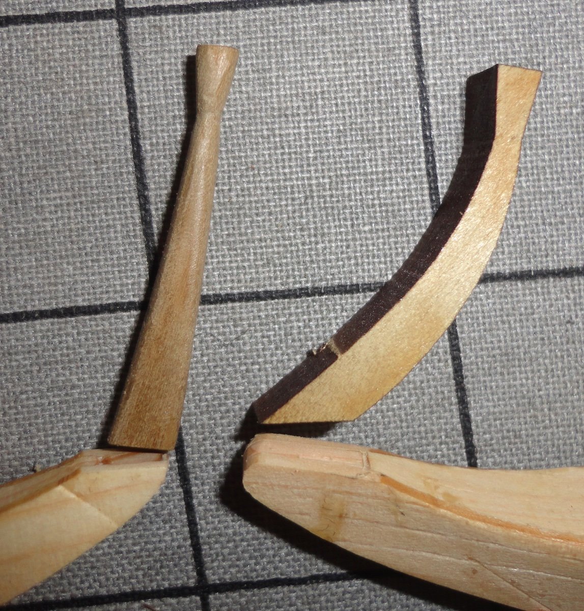
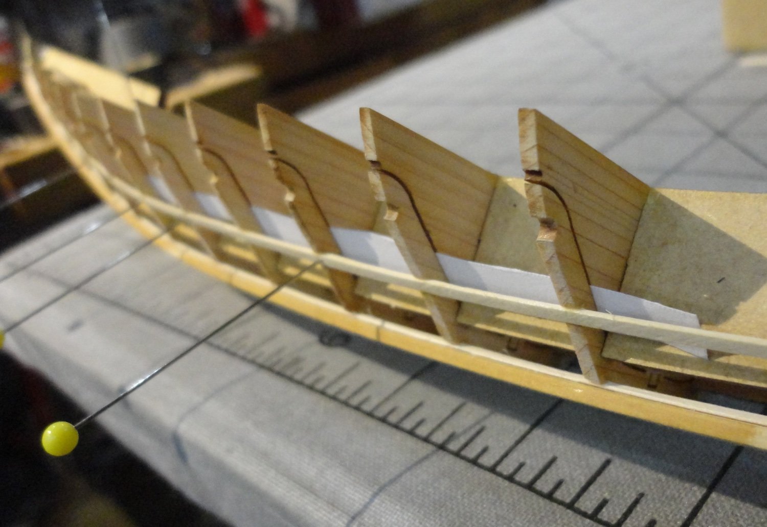
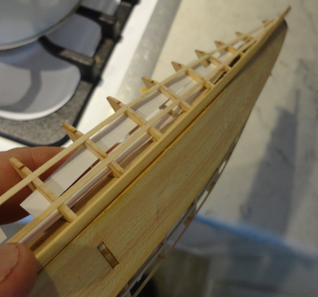
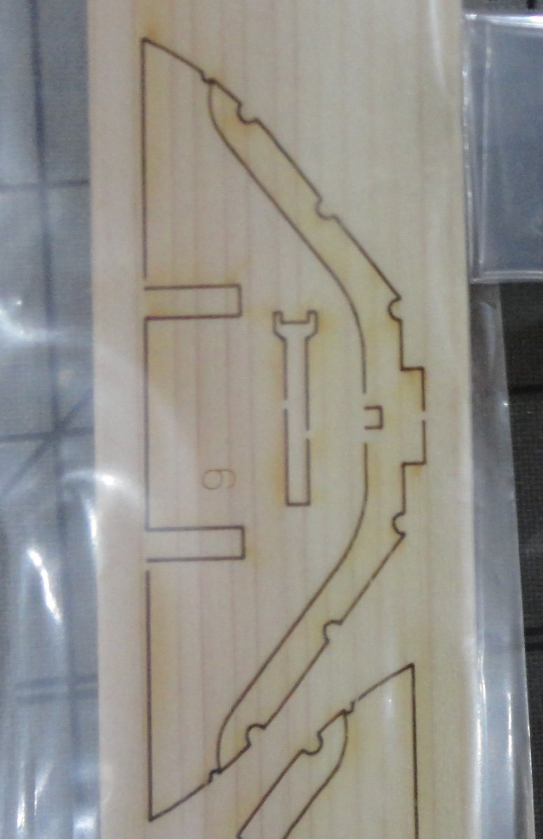
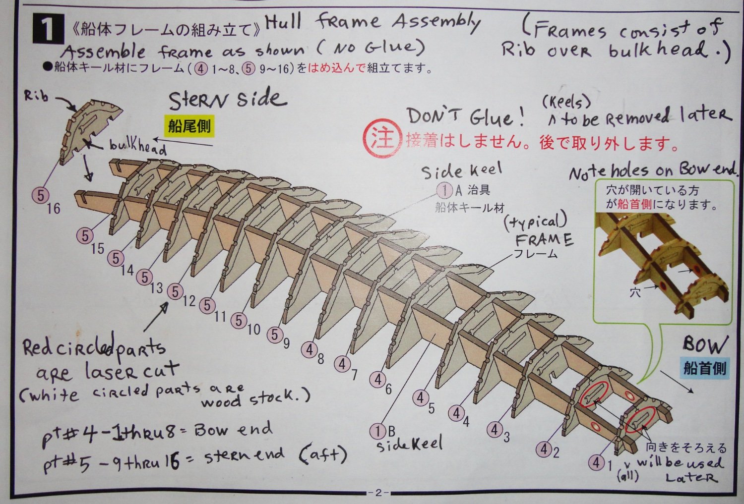
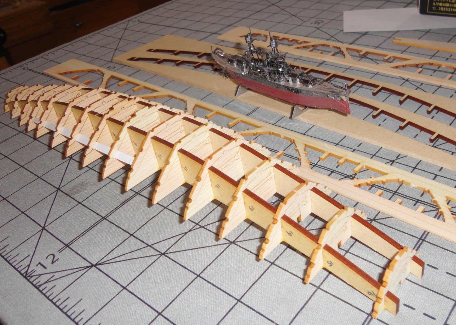
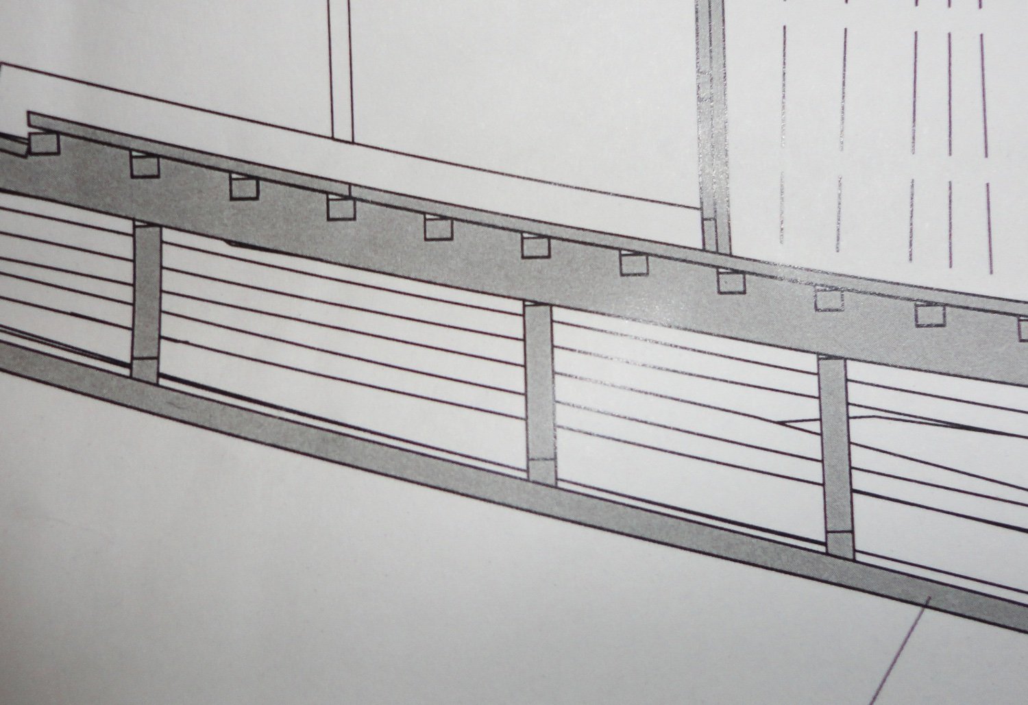
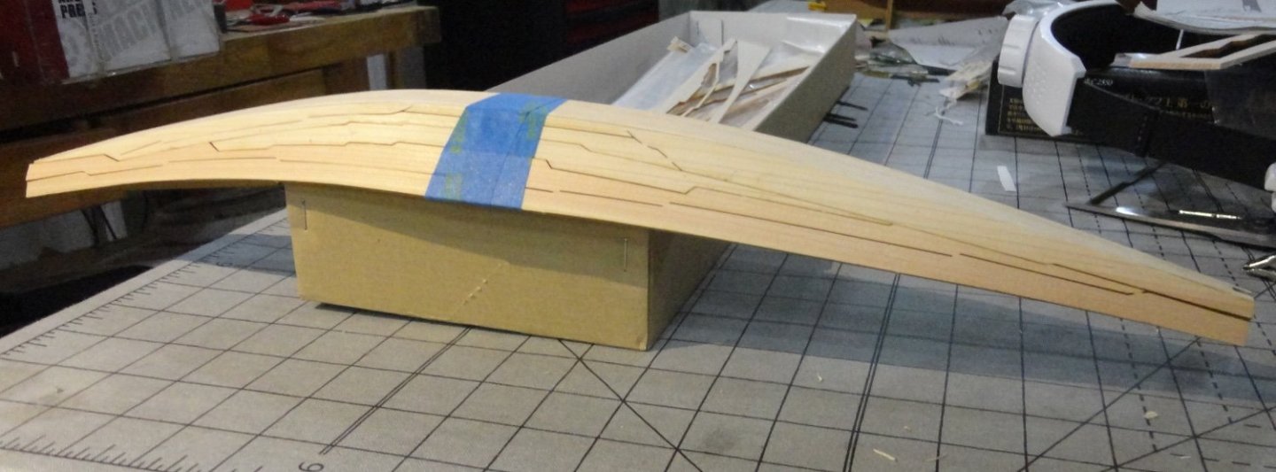
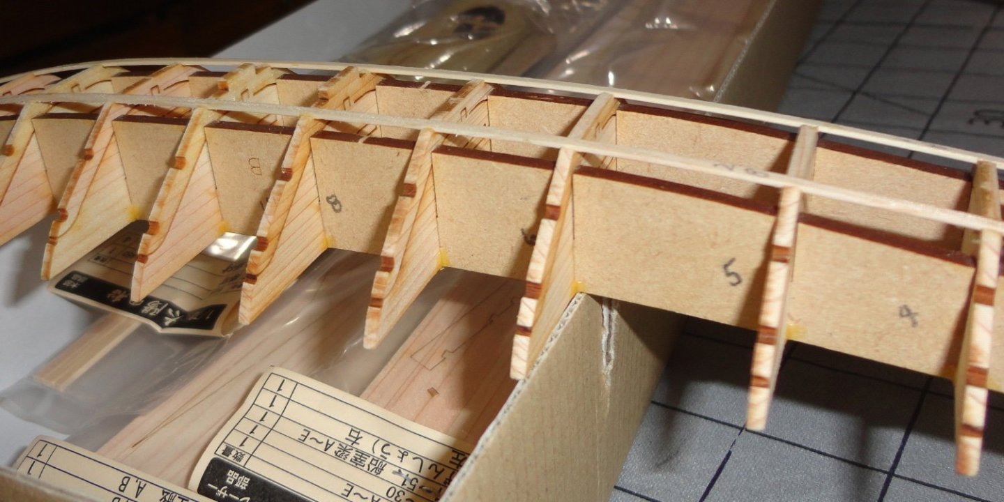
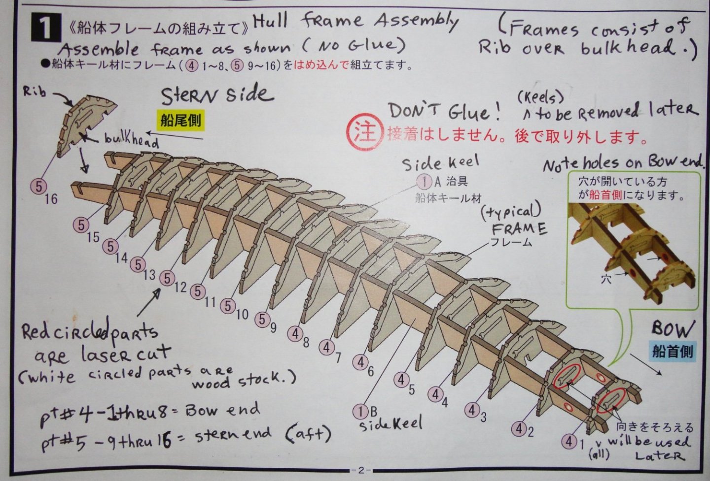
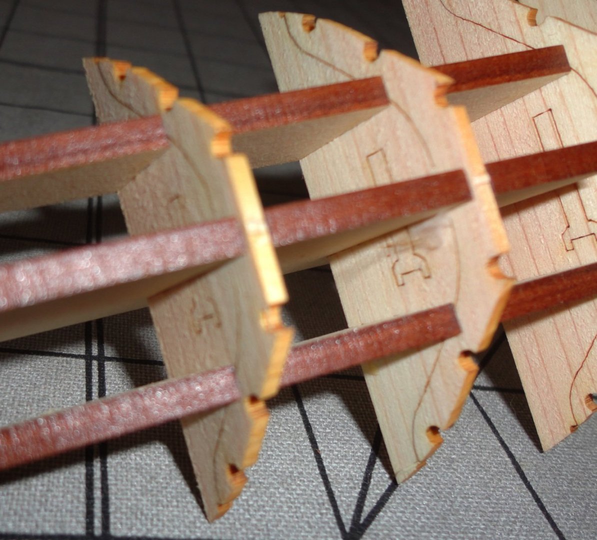
Ahoy mates ! Well, I've started this 'palate cleanser' kit based on some nudging from fellow modelers. I do not rush anything, yet the absence of masting, sails and rigging make this interesting kit one that can be done in far less time that many others. I reviewed the Woody Joe kit (unbuilt) in the Review section, and suggest that the log there be seen - since I don't want to repeat information contained there (with a few exceptions). I knew I'd be 'into' this model, since I like 'early stuff' - and will get around eventually to build the Billings Roar Ege (as a further prelude to doing the Billings Oseberg - and I want to do the best job on that one). I can't say enough about the quality of the laser cut parts on cedar stock in the Woody Joe kit. There are just a few breaks as 'attachment points', and an X-Acto knife breaks these easily. The parts then come out easily, cut to precise shapes with very little 'burning' on the edges. The frame (bulkhead) in the image below (detail from a pic in the review) shows how the rib (the only part to be left behind once the hull is planked) is almost completely free of the matrix to allow for ease of removal of the rest of the frame later. The width of the laser cut is about .006" - the thickness of a filing card (more on that soon). Care must be taken when handling these parts so they won't break. Now to step one, with my 'translations' written in. This step is meant for assembly with no glue, but there will be an exception. Once fitted, the framework is pretty good with little flexing, but the frames can be dislodged from full engagement - so the 'exception' to gluing (which even the kit instructions later mention) solves any slippage problem and renders the assemble pretty solid when dry (titebond glue). First, lets see the initial assembly. As you can see, I've inserted a strip of filing card stock in the tiny gap left by laser cutting the ribs from the frame. I will be putting a lit more of these spacers in before planking to prevent inward movement in these areas. The kit instructions expand on the clear pictures, but do not address the gap issue (easily solved). Oh yes, the little metal model (6" for and aft) of the USS Arizona was another 'palate cleanser' I did a build log on. It was a tricky thing to make, and I wanted to show that I DID complete a build earlier (last year) on the forum (check it out for yourself) as I was stuck on the problems with 'fixing' the old 1:100 Billings Wasa - now on hold but substantial progress was made last Winter. A closer look at the framing. Really, the design and execution of this nifty kit is ingenious - I love it already ! Now we come to the issue of fairing. Looking at a small portion of the full-size drawing of the model (needed for the build, as one must get a number of dimensions off it), you can see that the bottom board (the original has flat bottom planking) is faired to the ribs. No doubt about it. But to make the temporary building framework removable after planking to the ribs and 'stringers', the frames have to go in vertically. The laser cutting is in x and y dimensions, so the bottoms go in 'stair step ' fashion. This is typical of many model kit boat hulls and requires fairing (discussed in detail in other builds and as a separate issue elsewhere in the forum). BTW, I use the term 'stringers' from my old stick-built model airplane days, where 1/2 fuselage members are built right on the plan and joined by a series of thin balsa square stock running fore and aft ... known as stringers. Khufu's boat has a few, (representing internal battens on the original). The kit can be built by a 'beginner' without addressing the fairing issue with an acceptable result - so the kit says nothing about it. But I'll take a little care to do some fairing without breaking any of the ribs - it may be a tricky business. Once decked, one can hardly see the interior - but I'm picky on doing some things (loose as a goose on others) - and I'd like the rear access deck (hatch) pieces to be removable, as they were on the original so men could get under for maintenance. Khufu's boat shows signs of prior use, and must have been his personal yacht - the final trip was to bear his body to the great pyramid. Below shows the exact places to put a dab of pre-thickened wood glue with a dental tool. I have an old bottle of time bond kept on its side, and the glue has lost about half the water content - so is slow as the molasses in January. But this 'thickened' glue has its uses ... it is sticker than 'as bought' glue, 'grabs' quicker and dries faster. Glue dab are ONLY placed on the outside corners of the joins in the frame - as this will be easier to cut for later removal. Step 2 in the instructions appear next that even mention this option. Sorry for the 'bright spot' in the picture just where the instruction note shows the place to put glue dabs - but I have pictured this above clearly enough. Now I trial fitted one central 'keel' to see the 'steps' that need fairing. Note that the bow is not symmetrical to the stern, ergo there are holes in the side 'keel ' pieces to keep the ends oriented correctly. There is 'stepping', but is hard to see in the first picture. The second picture shows the stepping better, and (as in typical fairing done with kits) it is the edge toward either the bow (forward of amidships) or the stern (rearward of amidships) that get sanding/trimming. Right now, I'm not sure how I'll approach this. Note the tiny 'relief notch' at the end of the rib to prevent gluing planking to the frame BEYOND the rib. This is essential to permit easy removal of the framework later. The central 'keels' (bow and stern) to not have any relief cut, and as I want to glue planking to the ribs there might be a danger of 'squeeze out' glue sticking to the 'keel'. This is easy to sone by removing small amounts of material shown by pencil lines in the next picture. The kit directions mention nothing about this, but I can see ahead based on prior experience. First timers often learn by doing, and re-doing what went awry reinforces the experience gaining process. Just a few small cuts will do. I trial bent (partially, without wetting) the bottom plank to see how the amount of fairing will change going outward - and this is different between the bow and stern since they have different amounts of bending. I may wet, heat and pre-bend planking as I go to lessen the clamping force (done in many places on this build with rubber bands - not included in the kit). 'Sorry, but the focus is off, or I moved a little (holding the camera with one hand). That's all for now, mates. And further progress will require a little more thought before 'jumping in'. If you hand a chimp a banana, don't expect him to think about how he's going to peel it (much less read instructions).


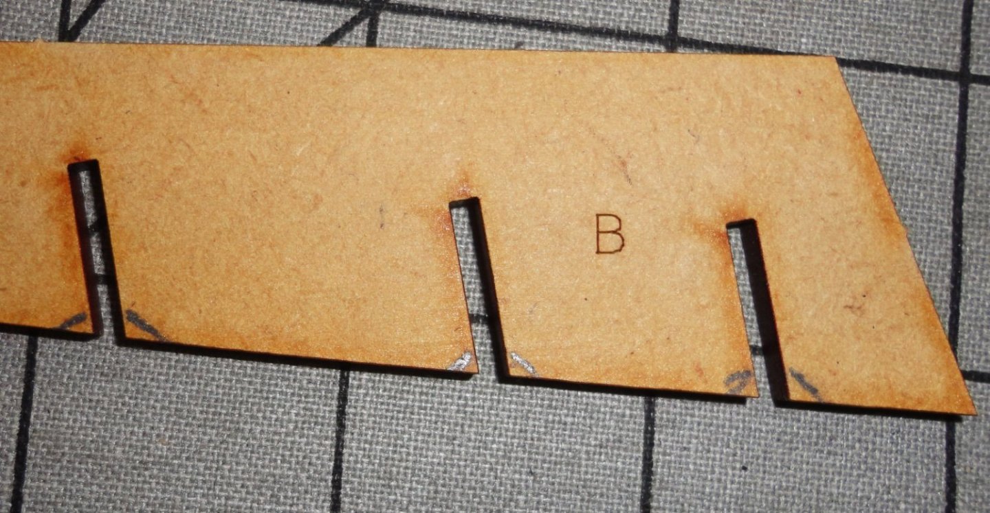
- 63 replies
-
- 8
-
-
- Finished
- Khufus Solar Boat
- (and 1 more)
-
Ahoy to any who might review this fine build from 2015-2016 . This Mamoli kit came to me from my Dad's estate intact, and the overall quality is decent ... the minor 'busts' in this build do it justice. I've pondered the GH for a long while, postponing any attempt to build it based on the Mamoli kit until I could find contemporary info on the original. Queen Elizabeth knighted Drake on the deck of the Hind, such that it was after limping home again with enough value in the hold to make an astounding profit. The ship had been towed a little ways up the Deptford while a mooring was prepared on the Thames (logical to do) - thus validating those who said it was moored on the Deptford. But the long-term home was on the Thames - eventually filled-in around the ship before it sank from rotting hull planking. Masting and ordinance were removed and a wood shed built over it ... eventually deteriorating, as did the ship. It appeared on two early 17th century maps in the same place on the Thames, and by 1630 it was described as having some ribs sticking up like a whale skeleton. Sometime about 1650 the remains were knocked down (some wood salvaged to make a few pieces of furniture (one chair is on exhibit in England), and the hold filled in for good. Later work in that area may have seriously disturbed more of the hull, but there may well be enough of it left so that future archeology may determine the hull length and beam at the waterline, and the lines there and below. There are no known paintings, BUT there is the famous Drake Cup (also on display). Drake gave Elizabeth a coconut, and she had it crafted with silver mountings to make a splendid ceremonial cup with a lid that she gave back to Drake some time later. There is an inconclusive line image engraved on part of the coconut, but the silver lid is adorned at the top by a silver miniature of the ship! THIS qualifies as a contemporary image of the GH, and the Queen was familiar enough with the actual ship that it most likely represents an approximation of the real thing ... realizing that there are some scaling/slight clumsiness involved with casting/soldering the silver miniature on the cup - given the techniques of the time. The miniature does not have a 'Captains walk' - like most French 'race galleons' (from razee - or razored - since the heights of the stern and forecastles were reduced). They differ substantially from period Spanish gallions. There are a gunport openings visible (on the miniature) on the weather deck (no guns) and the Mamoli kit guns are on the weather deck (opposed to the Thames reproduction - thus other kits - having guns below the weather deck - orlop?) There is a stern spar to rig a large lateen (no sails on the miniature) as seen in contemporary engravings. The main and fore masts have a sail and topsail each, and a yard on the bowsprit. There is a contemporary engraving (with ship distortions of its own) depicting the capture of the Cagafuego by the GH off the west coast of South America ... no captains walk on the GH, which has many similarities to the silver miniature. The detailed engraving of Drakes 'Caribbean Fleet' also agrees with the miniature. So what about the size of the original? An experienced Portuguese navigator surnamed DeSilva was captured in the Carribean, and accompanied Drake on the GH around the horn and up the coast until being let off in Mexico (presumably Drake did not want a navigator to witness any possible discovery of the Northwest passage, which Drake was to attempt). DeSilva was fluent in Portuguese, Spanish and English - with some French, and was the personal guest of Drake on the GH and had the run of the ship. Later DeSilva was questioned by Spanish authorities and the dreaded Spanish inquisition - transcripts of both depositions were recorded and exist to this day (English translations can be found). DeSilva was likely suspected of collaboration, thus was closely questioned to get any scrap of information about Drake and the ship he sailed. DeSilva's life and his immortal soul depended upon the accuracy of his testimony - so I' be willing to 'go to the bank' on it. DeSilva said the GH was French built and not new - ergo purchased by Drake with funds raised for the venture. There were 7 guns on each side for a broadside (5 each side of the deck, and presumably 2 on each side of a quarterdeck as was typical of French race galleons depicted in surviving illustrations) plus 2 stern guns (typical) and 2 at the bow. It is unclear is they were light guns on the forecastle deck (a possibility), but I think it more likely that they were on the gun deck covered by the forecastle deck angled about 45 degrees toward the front. He declared the tonnage (in Old Portuguese Tons) to be 220 - which computes to 180 of today's Tons. This represented the cargo capacity and DeSilva was expert enough to assess this properly. The Thames reproduction was that of 150 tons (yet having the length on deck of a 180 ton vessel), and proved unseaworthy until side pieces were added at the waterline - then it went all over the world by sea ! The reproduction - as does the Mamoli kit - has a mere 19 feet beam on the weather deck and 23 feet at the waterline (as originally built). Ergo there indeed is not enough room for cannon carriage recoil, so the repo (and some kits) have the guns on the next lower deck of 23' beam. A 180 ton vessel will have 100 feet 'on deck' (fore and aft - much like the Thame replica) BUT will have about a 23' beam on the weather deck and will be 28' at the waterline. The GH of these dimensions would have had enough room for guns on the weather deck to recoil, and enough room below deck to house the large crew Drake had at the start of the venture. There also would have been room (as the crew size shrunk from losses of various causes) to eventually store tons of loot and a very large cargo of far-eastern spices. The side 'bulges' added to the Thames replica give it the needed breadth at the waterline that, if the ribs were revised to match this beam, would give 23' on the weather deck. BTW it has the 100' on deck mentioned earlier - and that does not include bowsprit. So by altering the framing Mamoli provides (widening the model), and taking into account some of the other features mentioned - a closer approximation of the Golden Hind can be had. Fair sailing ! Johnny
-
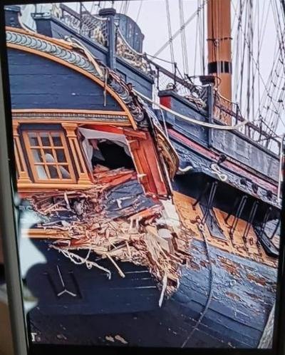
I've attached a photo of the aftermath of the aftermath of the collision of HMS Surprise (formerly Rose) with a seawall while being nudged by a small tug to a repair facility about 3/4 mile from her museum berth (presumably for hull planking repair). The photo speaks for itself, but I found a Youtube video showing the collision in real time with sound ... like a train wreck in slow motion (crunch). I'm not a tech, and the file may not work on the forum, but anyone can search under 'HMS Surprise crashes into a wall'. 'Not sure what they were trying to do, but the tug was on the 'blind side' of the Surprise ... and had no line of sight with the seawall. The backing speed was much too fast, and the lookout had communication difficulties with the tug. HMS Surprise crashes into a WALL at Marine Group!! - YouTubehttps-::www.youtube.com › watch.weblocHMS Surprise crashes into a WALL at Marine Group!! - YouTubehttps-::www.youtube.com › watch.weblocHMS Surprise crashes into a WALL at Marine Group!! - YouTubehttps-::www.youtube.com › watch.webloc
- 481 replies
-
- 1
-
-
- Cutty Sark
- Revell
- (and 2 more)