


Dan Vadas
-
Posts
3,261 -
Joined
-
Last visited
Content Type
Profiles
Forums
Gallery
Events
Posts posted by Dan Vadas
-
-
-
Thank you Fernando
") .
.
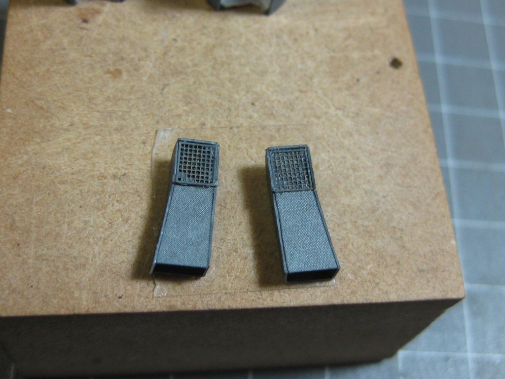
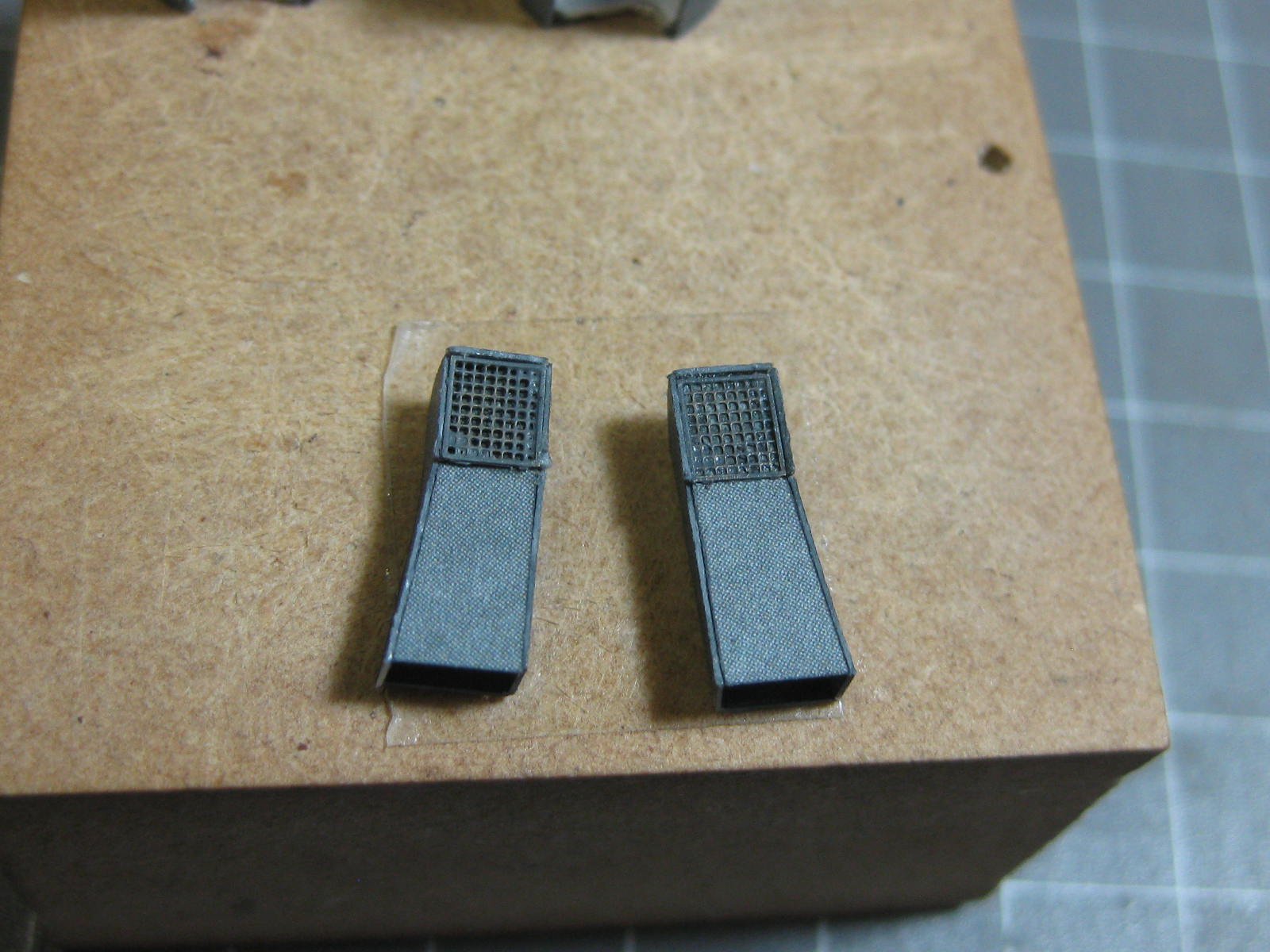
More bits and pieces to fit under the deck - two Vents with PE grilles ......
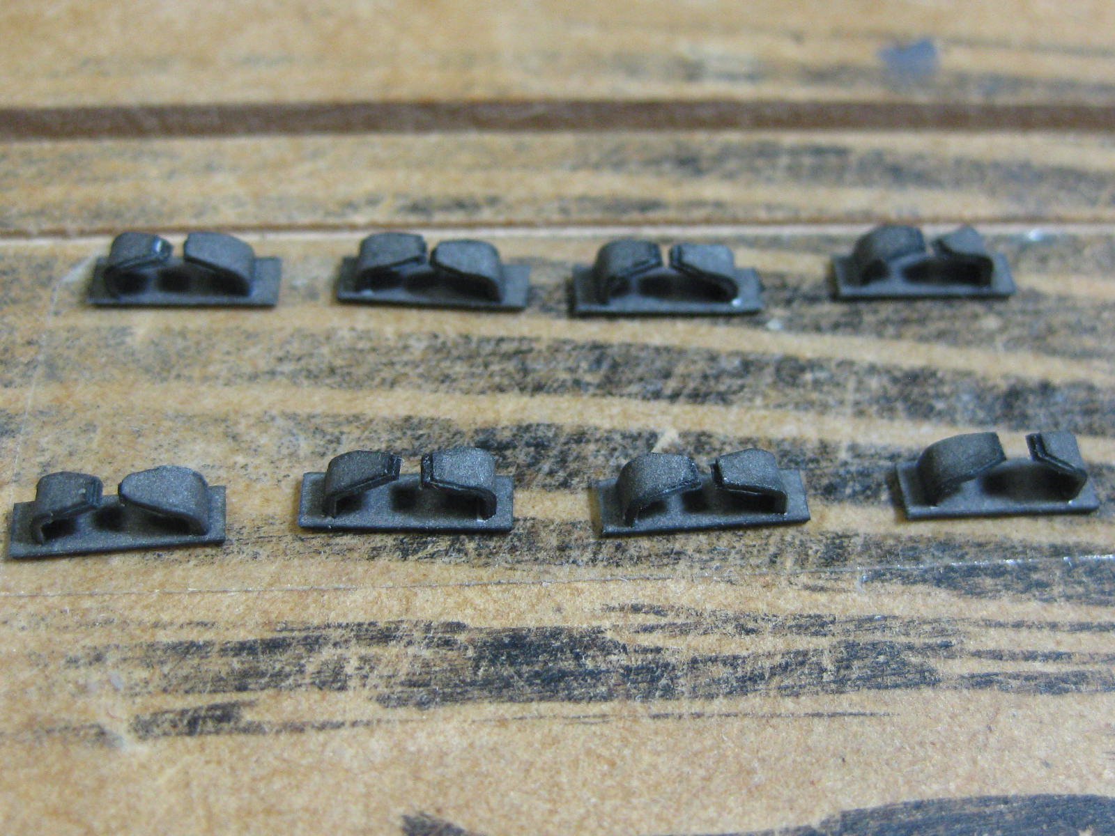
..... a bunch of cleats .....

..... four large round things (no idea yet) .....
.thumb.JPG.aca93c13b59008ac37733cba8c4c8e92.JPG)
.thumb.JPG.78ca6207765ac6601ba4004cec11e3c2.JPG)
Next step was to fit an edge strip around the deck :
.thumb.JPG.49188eae420d388163c4ffc61a29ad6f.JPG)
.thumb.JPG.f5c8454f42856ad894521475d5725c3b.JPG)
.thumb.JPG.689f3483946408cc97dea88b47bbb8b6.JPG)
Even though they will be difficult (not impossible) to see there are 16 Gussets under four sections of the deck :
.thumb.JPG.50b68d5120f5e7a28aabad5bac9305a5.JPG)
.thumb.JPG.58ee5eca00360fb7363a4192f19c7eaa.JPG)
Now I glued the deck on. The thin Pillars (1.0mm wire) were fitted after it was on. I drilled holes for each one before gluing down the deck to make fitting easier :
.thumb.JPG.4815097438f92c1974084cea4ec0d4d8.JPG)
.thumb.JPG.404389853a5502d3cfda94feeccf0859.JPG)
Some views under the deck :
.thumb.JPG.786cfb116686f0100cfd503e488c253f.JPG)
.thumb.JPG.63ae738f911e4c23f8cf8d55b0a1486a.JPG)
Danny
-
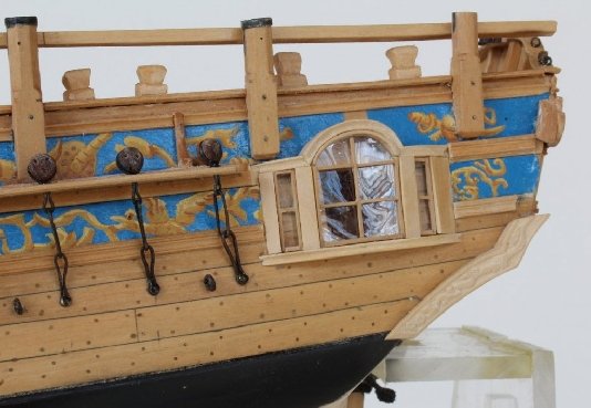
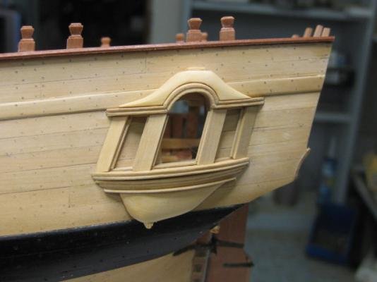
Toni, I hate to be the bearer of bad news but I have to agree with David, your lights look far too square. It looks like you have made the verticals at 90 degrees to the waterline, whereas (from memory) they should be at 12 degrees from the vertical. Take a look at the difference in the pics below. The verticals should be about the same angle as the transom :
Danny
-
-
17 hours ago, cog said:
That jig must save some time, and frustration! Makes it worthwhile to invest the time.
Not a lot of time saved Carl, but certainly a lot less frustration
 .
.
I was wondering why the kit's instructions suggested making a few seemingly unrelated pieces as the next few steps, until I looked at where they go on the deck. It would be very difficult to fit some of them after the next deck goes on
") .
.
First of these are 6 Ventilators. They consist of a round top (I punched them out), and a strip that needs to be rolled around a wire. This was very fiddly to do until I used the self-closing tweezers to hold the wire :
.thumb.JPG.58e81d01478af765d822b93cbfee5751.JPG)
.thumb.JPG.1425799dc7fed2edc77c1e46a5a0dcca.JPG)
Next up were a couple of Bollards. I decided to make all of them while I had everything set up.
Rolling the 26 pipes was looking like being another frustrating exercise until I came up with the idea of using one of my CA applicator needles to roll them. This worked great, I could do one in under a minute compared to 5 or 6 minutes trying to roll the first one by hand :
.thumb.JPG.3c17037e9e1463f7a27975f14014a7f6.JPG)
I wasn't sure how they were going to come out, so I stopped rolling them with the needle after I'd gone about halfway and then roll the rest by hand - a bad mistake, this was difficult :
.thumb.JPG.612df3b6db04259c41d08143d8e49b15.JPG)
I rolled the next one all the way on the needle. EXCELLENT
. A drop of glue 5mm from the finish and then roll it out is all it takes to hold them tightly :
.thumb.JPG.b1ccaad452f1c23dbeff065b1ca1e6d9.JPG)
.thumb.JPG.0193776db92d1200a358fce429d5c031.JPG)
The bits for about 12 bollards :
.thumb.JPG.99100a3c64bdbf9c19e34b5506ca4f64.JPG)
I glued them together on some double-sided tape :
.thumb.JPG.c51563cd79f7f14c48b9243fe3147126.JPG)
All of them done in about 2 hours total time :
.thumb.JPG.0237a2082aa000ab68a23b1d44ac2484.JPG)
.thumb.JPG.8568f1ef10e9ffb219c4b4017d9b84fc.JPG)
-
Thanks again Nils, Paul and Popeye
.
There are a lot of Reels of various sizes and types to be made. These ones will be hardly seen, as they are inside the lower superstructure but I'm fitting all of them anyway.
Each is made from 4 pieces of PE with a card spool. The two supports are about 1.5mm high, and the rim is 2.5mm in diameter :
.thumb.JPG.d9ea015129426758b120f11602e8c2c9.JPG)
.thumb.JPG.64935808b7bd8410e089cefaaa940142.JPG)
The first 9 of a myriad of small boxes. I made a jig to help hold them while the glue dried. A piece of card underneath the piece prevents any damage when I push it out of the jig with the piece of 1mm wire :
.thumb.JPG.490a6d625f529c416df3ba31b57f2af3.JPG)
I glued a strip of thin paper around the inside to help hold the corners :
.thumb.JPG.a9679f01e884a3efcff70c3e3da3ae4b.JPG)
.thumb.JPG.005fd2bf1356a72bba168e189a1d1b76.JPG)
.thumb.JPG.f1946d16141757d914fafa6875cdbda3.JPG)
Danny
- FatFingers, robdurant, ccoyle and 15 others
-
 18
18
-
Thanks OC. I've already checked the colour scheme for Hood at the time of her fatal encounter with Bismarck, and she was painted Admiralty Dark Gray all over. I have some on it's way already. Unfortunately the shop I'm using didn't have it in Lifecolor brand. I wonder how Meng goes on, never heard of it before.
Danny
- popeye the sailor, Canute, mtaylor and 3 others
-
6
-
Cut a flat angle in the end of a toothpick and lick it. This works well for parts that are a bit small for tweezers.
Use one or two tiny drops of PVA glue to position the part, allow to dry for a few minutes, then apply CA glue. A sewing needle with the end of the eye ground off, held in an Xacto handle, makes neat work of applying a small amount of CA.
Danny
-
Thanks OC
.
On 06/04/2018 at 7:41 AM, Old Collingwood said:so much commanality between hood and warspite with the position of the props.
Not surprising, as they were built within a few years of each other. Hood was commisioned in 1920, and Warspite was a bit earlier, launched in 1915.
I've made a start on the lower superstructure, almost completing both forward and aft sections. The aft section is fairly straight-forward :
.thumb.JPG.c024e3f75700f352675647b99addb434.JPG)
I've used the PE doors that I bought from Halinski, as the printed ones had almost no detail :
.thumb.JPG.318785436ea244960db0754831973b5c.JPG)
The PE ones make up for that, consisting of two pieces for each door. The outer surround has the watertight catches etched into them, a good facsimilie of the "real thing" :
.thumb.JPG.8104c3ad3a1ac54dce7da29649b6ed33.JPG)
.thumb.JPG.b479bbe22278d5457fe9f2394b2b9f72.JPG)
.thumb.JPG.618dc909e71f1e34a3137227a141d2df.JPG)
These are only in primer, I need to buy a few jars of various greys.
The forward section makes up for the simplicity of the aft one. Ins and outs everywhere
. I added a lot of extra card to the basic framing :
.thumb.JPG.acaf949a611c6196ce58844b79f87195.JPG)
The walls consist of three sections. Some thought had to go into which way to fold them. The last pic shows one wall ready to be fitted :
.thumb.JPG.77dc9bd12fbebc1f30b1207a11d54e28.JPG)
.thumb.JPG.ca25326ce24588d36949728696391fbb.JPG)
Danny
- hexnut, GrantGoodale, FatFingers and 13 others
-
16
-
-
-
One of the more difficult steps in this build is an Edge Strip that runs around the whole perimeter of the hull. It needs to be laminated to some 0.25mm card and is only 1mm wide for most of it's length, so cutting it required some degree of care. The pic below is of the pieces needed for one side of the hull :
.thumb.JPG.65d2f13914caf43c336560791859dff9.JPG)
.thumb.JPG.29cbda61d4fef5973211d05c69df6a34.JPG)
The forward section of the strip protrudes above the deck, so I've left it off for now until the hull is completed to avoid an accident. Below are a couple of pics of the strip fitted :
.thumb.JPG.c8cb5b27cda6131ce35bf59e040887b9.JPG)
.thumb.JPG.34d9bf9794910f00f50e7aafd66ab45b.JPG)
Another tricky bit were the Bilge Keels. These are in a triangular shape, rather than the flat back-to-back keels of my previous models. I glued the outer edges together first :
.thumb.JPG.2dd95d303f6457f611e38b258390da4a.JPG)
The keels fitted. They came out really well
. Also seen in the pics below is what I assume to be a Rubbing Strip. It's at the widest part of the hull, so my guess is it was needed to avoid damage to the hull when berthing :
.thumb.JPG.440bf21a200452d79f4d9a5c7ef7da70.JPG)
.thumb.JPG.5d1d231c0c86c8e9a8ef6374bb95e40d.JPG)
The final piece of the underwater part of the hull is a Paravane Fairlead at the bow :
The hull is now complete and can be turned right-way-up for the remainder of the build.
Danny
- Fernando E, BenF89, BETAQDAVE and 17 others
-
20
-
Thank you David, and welcome to the build Richard. Yeah, it's pretty amazing what they can do with Card in these days of Computer Design
.
Continuing on, and some of these pics are probably out of build sequence but I've grouped some of them together to make it a bit easier to follow.
I've fitted the rudder and made it moveable, a trick in itself when it came to fitting it as I'd glued on one piece that I shouldn't have yet. I had to partially remove the lower guard to slip the 1.0mm wire pivot wire past it, but all was good in the end and no damage was caused :
.thumb.JPG.a7b46be8391f9d719d512873537da2fa.JPG)
.thumb.JPG.8151be8a140a67f87e6007e800e5a039.JPG)
.thumb.JPG.f83257b805aebbb3382ab33285dc638a.JPG)
I've also fitted the prop shafts. Some of the housing supports were numbered incorrectly, and I had to remove and refit them to align them properly. Again no big deal, they fit perfectly now
. I'll make and fit the propellers late in the build to avoid damaging them :
.thumb.JPG.9eddbcafb1b841d8bac0e4218b8cb1f5.JPG)
.thumb.JPG.33c56ec40fb0ab1ef4e406d0206177e8.JPG)
.thumb.JPG.5f145cbd0c9db31a28cd60cc748b227e.JPG)
.thumb.JPG.75b4a916830949aa29d2dc268457a486.JPG)
Danny
-
-
6 hours ago, gjdale said:
Only problem is, the Admiral has presented me with a list of other projects she wants building now that I’ve had some practice
You've blown it now Grant - this is the end of your "me" time
.
Danny
- gjdale, thibaultron, src and 4 others
-
7
-
Thank you Carl.
I've made and fitted all the Prop Shaft Housings and also the Shafts, which are rolled around a 2.5mm brass tube for strength. These have turned out much straighter and stronger than any I made previously. I've also cut and edge painted all the aft housing supports :
.thumb.JPG.cd205bf995ad0d42b9a539e9a0c01be8.JPG)
.thumb.JPG.bf1784762ac3967f8f3eef0ea1d6b31e.JPG)
.thumb.JPG.bd0859ad6099d09f8807f735a848c500.JPG)
.thumb.JPG.98ef4d445c026ae40bde32382b8006d8.JPG)
.thumb.JPG.2c045442e5f262474f75f023b1a46918.JPG)
While I was working in that area I thought it a good idea to also make the Rudder :
.thumb.JPG.b3ef9764e0e457384afb2e1bfe0158c4.JPG)
.thumb.JPG.f2c770c1b276428899e92bf77b916686.JPG)
Danny
- marktiedens, herask, robdurant and 13 others
-
16
-
-
Thanks guys
.
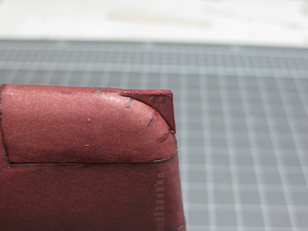
Fitting the forward Hawses proved to be a bit of a problem. This is the first mistake in the kit that I've found - the parts for the internal holes have been printed back-to-front. The reason for the mistake is probably due to the fact that these parts need to be rolled in the opposite direction to virtually every other rolled pieces, something that Halinski must have overlooked :
.thumb.JPG.07aee659d5af853494901c0a9c605a9b.JPG)
The two main holes weren't a problem, as I simply switched them left-to-right. The third hawse hole fortunately has a cover over it (it must have been removed if the 3rd hawse was needed). Here are a couple of pics of one of the hawses :
.thumb.JPG.10e62aa810dbb1c869d743911c60e7fd.JPG)
.thumb.JPG.f3189a28e593c734b8af5ad350bca740.JPG)
To fix the 3rd hawse I first rolled it and glued the join. Then I cut it in half and turned the upper part 90 degrees and glued it back together. It didn't fit perfectly (I was probably a couple of degrees out) but as the top section can't be seen it doesn't matter
:
.thumb.JPG.b51ad0d3d0f7916ee07081b77442d505.JPG)
The hawses fitted. No filler needed
:
.thumb.JPG.bfd9e691b82dcc2e00f135f192aa513f.JPG)
.thumb.JPG.180d21c7d065764a02844f42ab813bcd.JPG)
.thumb.JPG.7e7d5c3713cb96dea53f897c63a267e9.JPG)
.thumb.JPG.9492783ec1339893e12755b9ce880b0c.JPG)
Danny
- FatFingers, druxey, paulsutcliffe and 9 others
-
12
-
1 hour ago, Thistle17 said:
I have yet to work out a good system for all the cables as you can see.
Zip Ties
.
Danny
- alde, Canute, Landlubber Mike and 1 other
-
4
-
Doing well Jobbie
. I find Selley's Aquadhere to be a little on the thin side. I prefer Fullers Maxbond - it's about twice as thick and dries faster as well. It's available at Bunnies.
NOTE - Fullers make two products with the same name (confusing
 ). One is a contact adhesive, the other a PVA glue. I'm referring to the PVA.
Cheers, Danny
-
I agree with all of Doug's comments. I have the 8-axis Mill and have never found the need to set it up as such, the Tilt Table and Rotary Table as well as a few other bits and pieces have removed the need to use the extra axes.
I also have the long-bed lathe, and I rarely use the extra length (I shape all my masts and yards by hand - it's actually a lot easier once you know the technique
). The long-bed lathe is useful in so far as the extra length allows you to move the tailstock well out of the way when setting up longer pieces that won't go through the centre hole.
I have both machines fitted with DRO (an absolute MUST HAVE in my opinion), and both share the one Readout box. Changing from one machine to another can be done in about 30 seconds.
In regard to your "Inch" Mill - about all you would need to change are the leadscrews and handwheels. I'd say this would be considerably cheaper than buying a new mill even if you got a really good price for the old one.
Cheers, Danny
- Landlubber Mike, Canute, Heronguy and 2 others
-
5
-
Thank you Fernando and Popeye
.
6 hours ago, popeye the sailor said:nice job on the hull bottom Danny.......at least you won't have to deal with the decks being off shaded
looks very good!
Very true Popeye. The aft deck is in two sections, and the join (halfway through the aft turret) is almost invisible to the eye where it's been printed
.
Danny
-
-
2 hours ago, BETAQDAVE said:
Perhaps a little feedback to Halinski is in order? I am sure that as they appreciate favorable reviews on their products, maybe they would also like being informed of the shortcomings of their products. Most of the good companies usually do. As you have mentioned they seem to have otherwise put out a great kit. I would send them your photos indicating the obvious error!
I doubt it was Halinski's fault, more likely the company that printed it for them got it wrong. Until two sections of hull were actually glued together it was impossible to see any difference in the colours.
45 minutes ago, ccoyle said:Off the top of my head I don't know of any instances in which Halinski has done a reprint.
According to their website they are about to release several reprints, one of Bismarck, in the near future.
Cheers, Danny
.JPG.f74b7fe35da65f926e2c6630b9bc5fc8.JPG)
.JPG.ee6f32ff74ab5abd47e3f6dd383a902f.JPG)
.JPG.511e43932a59f81ae48af6c628e6d788.JPG)
.JPG.af2536de38ff1787e801db1c9b0f74d1.JPG)
.JPG.2a4df95cd3f013270293e0271f342f45.JPG)
.JPG.32cf6282e0795ed6b5f1a12296e37450.JPG)
.JPG.529481b8e66ca15d61e9dc74849d2a51.JPG)
.JPG.2e8f84ce9008a5a9d65cd55e58caca30.JPG)
.JPG.6fec0d08dc752bebb9579cef9e820191.JPG)
.JPG.11ec487e900b7e5c8d627c3cb8a07269.JPG)
.JPG.f2f020f2316bd8b0f3b416b5187c2e72.JPG)
.JPG.babb6ca7a9a8a16a293cae9907c3adcb.JPG)
.JPG.d6f9fe97e8b047a72e35321c5c14ad4c.JPG)
.JPG.0f92aaf980a07247525ab819be764861.JPG)
.JPG.37ca8b389edc4ca51ac5752fac5596a9.JPG)
.JPG.a6161de1068369aa76a7f5d30d9eda04.JPG)
.JPG.1b8c4cfc22a321274b7a73eb9ac888a5.JPG)
.JPG.d1b820b8446bdd5a0dc2d99e838ea375.JPG)
.JPG.3572a327407a5caf68fd391edd95661e.JPG)
.JPG.15668fb6204a55526be9eea24c612659.JPG)
.JPG.56be79438619407c2fc5ba03984eaa3a.JPG)
.JPG.2ad72e68c4f70bf723d7d0989222ef9d.JPG)
.JPG.4cfd9df6f61a92b8f302e82de10892d8.JPG)
.JPG.be856a07082c8117d07d6183cda6f624.JPG)
.JPG.f7bd0f056323bb2a4be7912a32a20627.JPG)
.JPG.e864746b72ad8f032c9d8b583a04af0c.JPG)
.JPG.acf8c22d902b8d9a04a7bb40ca16db7d.JPG)
.JPG.caf6d6b7b3d05ffe5dcf5ac28df1e098.JPG)
.JPG.cc12df97b90af838ef4ca8fe8556cf50.JPG)
.JPG.112ac3e4449fc3e2f2ff9be02f3dbf86.JPG)
.JPG.120b65061e443c96e58571a404af5ff5.JPG)
.JPG.94724a8305bd7b914a79f06a43f00920.JPG)
.JPG.f3ac4f5f324a476b339440ab550aa758.JPG)
.JPG.feff52da2d7201a36e92a5b741120782.JPG)
.JPG.192dec1ec8bbd81e7d0da232bdbde1cf.JPG)
.JPG.9157fca3a72299e8e02e2a62f5efabd8.JPG)
.JPG.4b4e1b8f6a411832a387668665e240cf.JPG)
.JPG.47f4dae0c8440483a43bc47dfda8b609.JPG)
.JPG.8639d0f8f460ce34c5711589531a579f.JPG)
.JPG.1fc292c96e7554a31c3d670be7e6ef47.JPG)
.JPG.dce25e009ba88541d3004b765867cab0.JPG)
.JPG.d0cc3392b36e164e211a97eff9f3dab7.JPG)

.JPG.064bca549160cf2ba5896454f74af88d.JPG)
.JPG.447f69584094b1e3cfdb9038efb71659.JPG)
.JPG.b327d819f081d74cb71c3a44cc89e8d5.JPG)
.JPG.bc3f3aef3e4489d30499ae35a6a85180.JPG)
.JPG.c965c2d4041f9c5460ebeb20356d1a5b.JPG)
.JPG.3f9e0e1849e802bcda3c9c2d980b34aa.JPG)
.JPG.70132bf95e1ca6e1bafcf506628bb0e3.JPG)
.JPG.0bbba02c9bd8f80326e5186865372ac1.JPG)
.JPG.21e0e48635587dd44d1e33bbafc21219.JPG)
.JPG.156ed535ad9519df3d0476c2cc48109c.JPG)
.JPG.0e55dc0b97acdcde88e636b8a2c3ff04.JPG)
.JPG.81a289c2922727f7f584665f6bff10f2.JPG)
.JPG.533193b33836fe4a777f428047a73a97.JPG)
.JPG.0fd1f8da90a04c7c9a3e7bee5eb7126b.JPG)
.JPG.6f6c234d52806ba02a5f7a69956fcce1.JPG)
.JPG.f4f0fdd8e92f55346e6ac098a52e47a3.JPG)
.JPG.8ec6aeb4f9d00687b0ad8cdd7c13b9c4.JPG)
.JPG.0e1047913a85661d96a299577c969229.JPG)
.JPG.9facdf633126155523260108d6f8f9f4.JPG)
.JPG.a47d8508837e099e0462ea6091f6de95.JPG)
.JPG.fd2bcbff21cbb325c9aeb1d1e4276dda.JPG)
.JPG.34d9f7994a4e92eef0f810031828057f.JPG)
HMS Hood by Dan Vadas - FINISHED - Halinski - 1:200 - CARD
in - Kit build logs for subjects built from 1901 - Present Day
Posted
Yeah, good one Popeye .
.
The 3rd deck is very complex. I've never seen this many corners on one before") . It also took quite a bit of thinking time, and a lot of dry-fitting :
. It also took quite a bit of thinking time, and a lot of dry-fitting :
The kit suggested cutting the walls into several pieces to make fitting easier. I managed it in ONE piece") :
:
Plenty of gussets under the deck. These took me 3 hours to cut and fit. As nearly every one was different I left the numbers on the back of the part before cutting and fitting them one at a time :
Danny