


Dan Vadas
-
Posts
3,261 -
Joined
-
Last visited
Content Type
Profiles
Forums
Gallery
Events
Posts posted by Dan Vadas
-
-
9 hours ago, BANYAN said:
Further on those 150mm guns, the independent fire control is the most likely reason, but rather than selective, I note the turrets ere the two central ones. Perhaps they could 'slave' the other 150mm guns on that side to the central one also?
cheers
Pat
I was thinking the same thing Pat
") .
.
 Danny
Danny
-
53 minutes ago, Walter Biles said:
Jim, I think some of those turrets might be selectively independently ranged and trained in stead of being run by the main directors.
From what I've read on a Bismarck site that would be correct
. The "things" sticking out are indeed Rangefinders.
Danny
-
Chuck, unless you want to be totally OCD about the Pump Tubes there's really no need to bore them all the way through. On my Vulture Cross-section I only bored the octagonal tubes about 15mm in at the top and 25mm in at the bottom. You can actually only see a couple of millimetres into the bore at the top once the chain is fitted. I cut out the bottom section (a cross-section within a cross-section
") ) to show the chains on two of the tubes. See HERE. The chains are also truncated.
Danny
) to show the chains on two of the tubes. See HERE. The chains are also truncated.
Danny
-
3 hours ago, cog said:
Still more guns to come?
Four little 20mm singles, and the four big 380mm Main Batteries (aka "Anton", "Bruno", "Caesar" and "Dora").
The turrets on Bismarck weighed 1,056 metric tons each
 . The barrels alone each weighed 100 tons. They fired a shell that was 1.7m long and weighed 800kg, and had a range of over 35km.
3 hours ago, amateur said:
. The barrels alone each weighed 100 tons. They fired a shell that was 1.7m long and weighed 800kg, and had a range of over 35km.
3 hours ago, amateur said:Ah you won't fool me: photoshopping your cutting mat into pics of the real ship
I wish I'd have thought of that, it would have saved me a lot of work
 .
Danny
.
Danny
- Canute, mtaylor, popeye the sailor and 4 others
-
 7
7
-
Thank you again Pat and John
.
The 150mm guns are fitted to the deck :
.thumb.JPG.5f8a47646460c0258ba950f25cfb47be.JPG)
.thumb.JPG.c934a93da79c722ac36b549b4f371d5c.JPG)
.thumb.JPG.099d9fd74bcbf8a419958773a3a95fc9.JPG) Danny
Danny
- paulsutcliffe, CDW, Charter33 and 20 others
-
23
-
-
The last two 150mm guns were a little different to the other four as they were fitted with Rangefinders, so I made them separately to avoid confusing the parts. Here are the parts for them in various stages of assembly :
.thumb.JPG.befecc497af443011f658256d7b8255f.JPG)
The two guns ready for the barrels :
.thumb.JPG.3f9f0805d1e8c46159250308758e6911.JPG) Danny
Danny
-
1 hour ago, amateur said:
I decided to do something drastic: remove all tabs
My first card model used Tabs, my last two didn't. I found the first one a lot harder to do. NO tabs is definitely easier, especially on small parts. I usually add extra card, folded, to give something bigger to glue to on the inside of a join.
1 hour ago, amateur said:I decided to give myself a (rather expensive) present
Now that you've bought the punch set you'll wonder how you managed without it for so long - a very good buy
. I also have the larger set, and use them both a lot .
Danny
- Piet, mtaylor, popeye the sailor and 1 other
-
4
-
Bismarck has six 150mm Guns as the 2nd Battery. Construction of these was fairly easy, but I had to add extra card to the few laser-cut pieces in the kit. I modified the bases to enable them to be swivelled :
.thumb.JPG.820ab253b13dad21243287a941aa9d45.JPG)
.thumb.JPG.9079d4bb15d8c0f255c6d98b17e54393.JPG)
.thumb.JPG.209ffb5de3c685afab6e8d12eaca1493.JPG)
.thumb.JPG.9ae24c1d9acf338e80e260fc97a6d741.JPG)
.thumb.JPG.e73c9cd7c1833f77d1cba9be583b4ef2.JPG)
The finished turrets. The bases still need to be glued to them :
.thumb.JPG.af48201054a5aab28470f29fa60cedf6.JPG)
.thumb.JPG.51b4f63e6d5e7ed12e028a3d40cd5db0.JPG)
I've primed the barrels, but I need to get another can of dark grey spray paint to topcoat them :
.thumb.JPG.1f3b3b53c53a831ff04cdf52c468c625.JPG) Danny
Danny
- cog, mtaylor, popeye the sailor and 14 others
-
17
-
4 hours ago, herask said:
I remember, the worst thing while building it was cutting all of the gluing flaps.
That was the first thing I thought about the kit too
. I reckon maybe a pack of 100 scalpel blades might do it .
That's a really nice model Denis, congratulations.
Danny
- popeye the sailor, Canute, mtaylor and 1 other
-
4
-
59 minutes ago, popeye the sailor said:
great job on the plane s and rigging Dan..........if you order one of those...post it in Shore leave! I'd love to see you build one
Thanks Popeye. The Yamaha (and 5 others) is a free download which I've already done
. If I decide to build one I certainly will post it in Shore Leave .
Danny
- Canute, popeye the sailor and mtaylor
-
3
-
Crikey, that was some reaction
 . Thanks for all the nice comments guys.
6 hours ago, druxey said:
. Thanks for all the nice comments guys.
6 hours ago, druxey said:I don't normally follow kit build threads, but your work on this card model is amazing, Dan!
Thanks David, I consider it an honour to have you view my humble work
.
6 hours ago, herask said:10 years ago I have spent 6 months building Yamaha paper model
Denis - I downloaded the card model Yamaha in your link to see what it was like. WOW
. The assembly instructions are "out of this world" - by far the best I've ever seen. A pity that you weren't involved with the artwork for this model - I'd have loved to see how it would have turned out if you had. The Rendering on your CAD "HMS Pegasus" is absolute magic , and would have made a huge difference to the Yammy.
3 hours ago, herask said:if it's OK with Dan I can post here
By all means - I'd love to see it
.
Such a pity I ordered (and paid for) the Halinski HMS Hood only two days ago, and it's already on it's way from Poland. One of the Yamahas would have been a nice diversion as my next model
.
Danny
- Canute, herask, popeye the sailor and 1 other
-
4
-
-
Thanks Pat and John
.
I've finally got to the stage where both Superstructures need to be fitted to the deck. I hadn't been looking forward to this stage much, as I wasn't sure if they were going to fit properly. I needn't have worried - there were only two slight mis-calculations (one each side) where the side walls didn't quite line up with the marks :
.thumb.JPG.0dd0de4a3a061aefc2eb17964c315154.JPG)
Before gluing anything down I dry-fitted both assemblies and checked out the fit. Then I ran around the white edges of the deck with a grey PITT pen in case any white showed after gluing (I learnt this lesson from Amatsukaze, where I had to do a bit of rather difficult touch-up after installing the superstructure
). Next I taped a couple of stops to the deck to make perfect alignment easier, and only THEN reached for the glue bottle. I'm more than happy with the result :
.thumb.JPG.9e50eb79e05df6cdfbbc62e44f2246cd.JPG)
With both assemblies now fitted I could finish off the rigging. First came the two Forestays for the main mast, which ended on either side of the funnel in two "turnbuckles" made from 0.2mm wire which I'd fitted earlier :
.thumb.JPG.2a007fb7d0c8f90b0ad4b8187001fcbe.JPG)
.thumb.JPG.226f47320821aa21d055d025894a06e8.JPG)
Then the rest of the antennae between the two masts. Four of these were a doubled line with a spacer at each end to keep them apart. There's probably a name for this arrangement, but I don't know it :
.thumb.JPG.f105c81c0cc27691b28188ea93bd0e5b.JPG)
.thumb.JPG.b31811a45592c03cb18c731ddbed3103.JPG)
To set up these antennae I first separated the wires using a short length of 2.5mm square wood. I made the spacers from 2.5mm lengths if 0.3mm wire, which was glued to the lines with a tiny dab of PVA at each end. When these dried sufficiently I applied a tiny drop of CA to each joint. These will be painted black :
.thumb.JPG.5be6481a08abdc8e4dfea176fd948d8b.JPG) Danny
Danny
- gjdale, robdurant, FatFingers and 14 others
-
17
-
I think it's OK Pav, I found some leftovers from Amatsukaze. Thanks anyway.
Danny
- mtaylor, Canute and popeye the sailor
-
3
-
5 minutes ago, cog said:
My 2 cents:
Cross the bars, loop a wire over the cross piece, pul underneath the other bar, and loop over the other side of the cross piece. CA to fixate it. You can get the full metal look by opening op the holes in the original part and fix it in place as if it part of it ...
Which is exactly what my Option 3 was. You explained it better
.
Danny
-
15 minutes ago, amateur said:
All pics of the plane show the canopy open (and with a visible gun)
I agree Jan. Unfortunately I don't have any spare guns to fit one in each plane. I'll think about scratch-building a couple. They were actually twin 7.92mm machine guns. See HERE.
Danny
- popeye the sailor, Canute and mtaylor
-
3
-
On 11/02/2018 at 10:28 PM, cog said:
does the other one look the same
Yes
. Thanks Carl and Paul.
Two Cranes are used for (among other things) recovering the floatplanes. These took me two days to make. They were very fragile until everything came together :
.thumb.JPG.c61660240bc4b5b278e9edb8d31aab4e.JPG)
.thumb.JPG.a773f9a0f6863bbb4675a028166e6ce5.JPG)
.thumb.JPG.78faf177778a3ebec1d544158f153566.JPG)
.thumb.JPG.afbba4a17a8005e8bc200cff813e9b72.JPG)
.thumb.JPG.9cad9dcc836e863908998b4f8837adbb.JPG)
The finished articles, ready to fit to the deck. The "cables" are "Fine" EZ-line elastic (black). The keen-eyed among you will note the temporary brass wires keeping the hooks from tangling until the cranes are fitted :
.thumb.JPG.9ef78f05f8c4c4e7de1b684ec35f2c1b.JPG)
.thumb.JPG.08bb3f57c9578192e6000178467b1c95.JPG) Danny
Danny
-
13 minutes ago, semorebutts said:
I wish I could just leave it off all together but some rigging line goes to and gets tied to this little mast.
Yeah, I know. Here's an overhead pic of mine (note how much simpler my details are compared to yours
) :
.thumb.JPG.b6254be26e01550dc5143674e7a23d5b.JPG)
One more alternative if you have any SOFT 0.2mm brass wire : fabricate the bracket from that by first gluing the yard to the mast, wrap the wire around the mast and yard, CA glue it on, and then trim and file it to shape. I'd probably have to draw a picture of what I mean. Once it's painted you wouldn't notice the difference.
Danny
- semorebutts, popeye the sailor, cog and 3 others
-
6
-
If it's too much of a problem - leave it off altogether. Who'd know (besides you and me
)?
An alternative would be to cut (or file) slots into the ends of the holes and open the holes up enough to slip over the yard, glue the yard in and then close up the bracket again. You'd need really good cutters though.
Or maybe make a whole new yard from wire that WILL fit through the holes.
BTW - those are Range Finders, not Radars
.
Danny
- Old Collingwood, Canute, CDW and 2 others
-
5
-
1 hour ago, Jim Lad said:
Do they fly?
No. I think there's a problem with the ignition
.
Danny
-
1 hour ago, semorebutts said:
these 2 guns need assembly and paint. I was looking to buy a PE set of them but they dont exist.
Yes they do Scott - 20mm AA guns
Danny
- Canute, cog, Old Collingwood and 2 others
-
5
-
16 hours ago, popeye the sailor said:
is there a rear section to the canopy?
Not in this kit Popeye - what is fitted is all you get. I think the rear section slides in under the main part to open it for the tail gunner - maybe?
13 hours ago, Walter Biles said:I am wondering what the T pipe behind the bridge boat storage might be.
I have no idea Walt
 .
.
Thanks Hof
.
BTW - after posting the pics above I realised I'd forgotten to fit the radio antenna. I've corrected that omission now. The antenna itself is some ridiculously thin (0.01mm) elastic thread, and the wire part is 0.2mm nickel-silver wire :
 Danny
Danny
- Landrotten Highlander, cog, ccoyle and 7 others
-
10
-
Thanks for the compliments once again John, Pat, Reg and Mark.
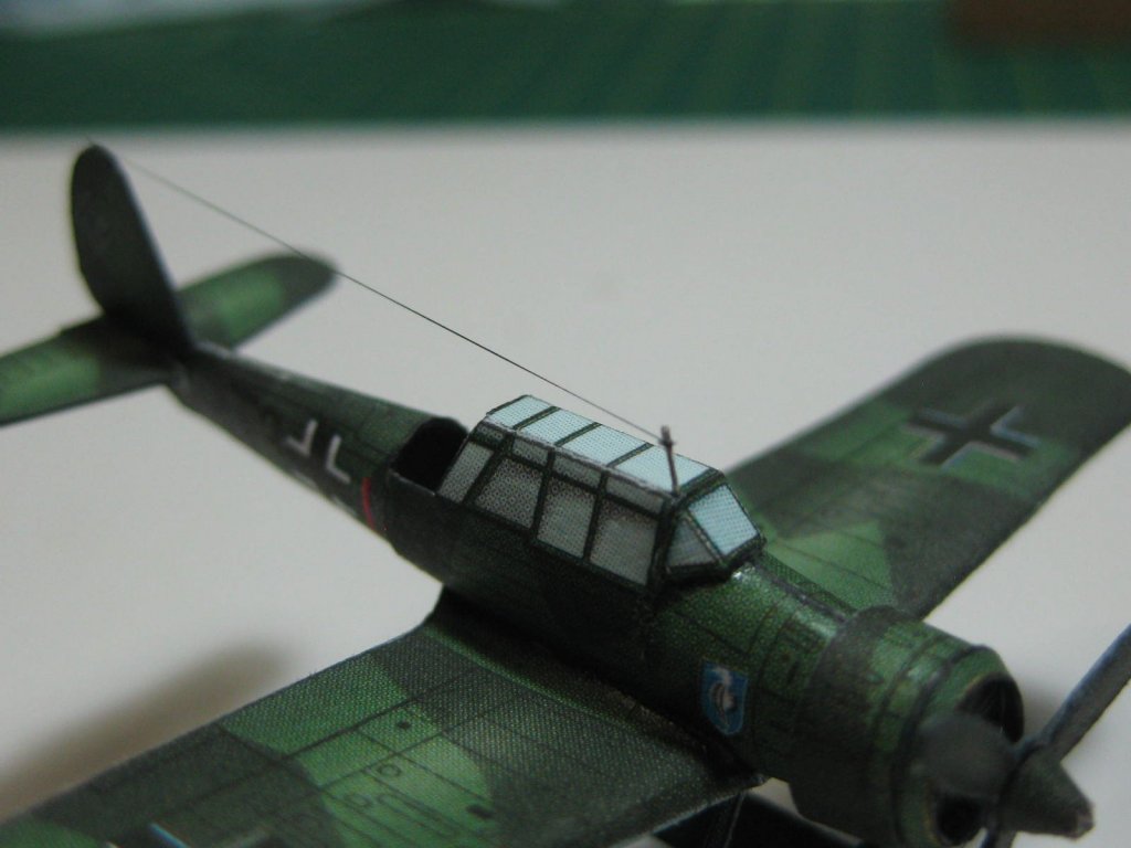
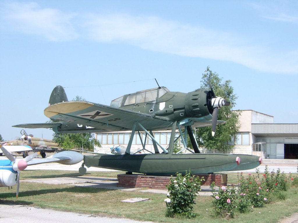
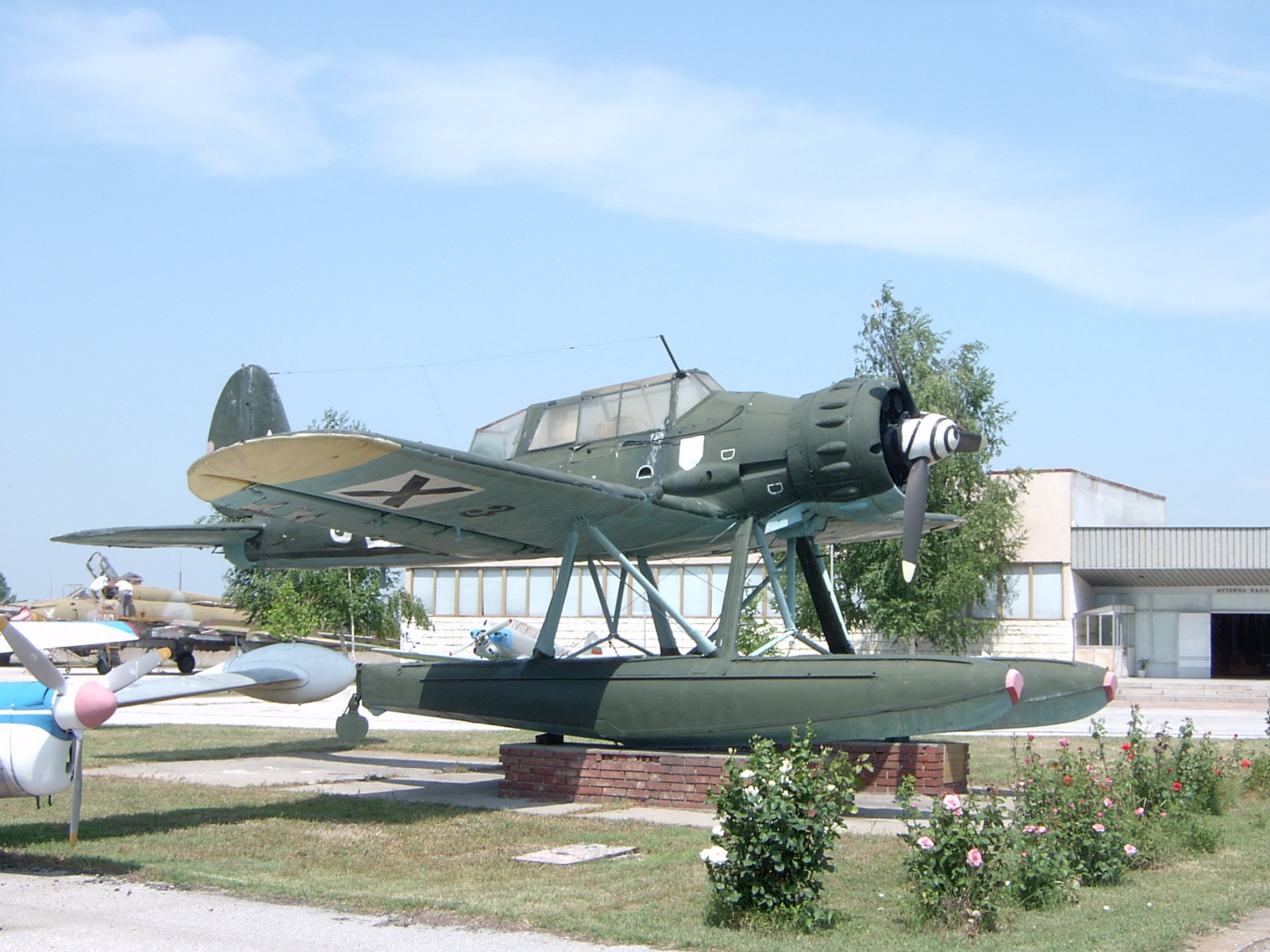
There are two Arado 196 Floatplanes on Bismarck. These took me three days to make. Once AGAIN the Instructions were pretty woeful - luckily I found a couple of good pics of the "real thing" online. Here's the best one :
The parts for both planes :
.thumb.JPG.a8fd86a4e9a5809810e33122ae3b744a.JPG)
Fitting the engine cowling edge piece :
.thumb.JPG.2c0ef928a21196adbabc109266ac6862.JPG)
The major pieces of the fuselage, wings and tail rolled, folded and glued :
.thumb.JPG.c9dfe89708d863f4e2912321872d8b8e.JPG)
The parts for the floats :
.thumb.JPG.3887fd9394fba71c1720a29eefa0eb32.JPG)
And some pics of the finished planes. The float supports were not easy to cut and fit :
.thumb.JPG.345df8651ae662947a8b4cf957249fc8.JPG)
.thumb.JPG.a82c098e48fbe186bf3e15698090db62.JPG)
.thumb.JPG.1e81e0667c3b11d3ae7f914ee0438927.JPG)
.thumb.JPG.82a9b9a6cdec53e9c0841d2129955e56.JPG) Danny
Danny
- egkb, mtaylor, Mirabell61 and 19 others
-
22
.JPG.2778014aac107911c148bb9d4f455ae9.JPG)
.JPG.7921c64dcb20fac46317565708d1b5b3.JPG)
.JPG.fa6a963767c9be34a6f191d3edc22c96.JPG)
.JPG.d4401c476f53959e0ecc1f007129542d.JPG)
.JPG.65ab4e6b671039215773234ba88821ef.JPG)
.JPG.395fd3f8504ed8bfa209f9ce4fd47795.JPG)
.JPG.31c621e2deffa69857ad783b29d1ea8f.JPG)
.JPG.e748a46cdffefaaba1a51584c891949b.JPG)
.JPG.03c8c5eac5b3118acbca2060000ac170.JPG)
.JPG.8f8f6431cc5c13549ace3f05f46dad1f.JPG)
.JPG.2ba3e214af7d07f46067c95942923c00.JPG)
.JPG.ed8b2b9274eebb91899d71f93962f5e7.JPG)
.JPG.f21445ea5756ca708ddab6fc8b609418.JPG)
.JPG.9484faa4c95dec1d025a1bfafe347e27.JPG)
.JPG.b95f2eb395747b59cbd2812d29b7de68.JPG)
.JPG.50fea7f847a80927ced6361cfede3f48.JPG)
.JPG.790c7f4f7ea8515fb020f326593fba0a.JPG)
.JPG.275c3ce31ad88eccfbc4a919a27a8176.JPG)
.JPG.7e65b4d24ded852bbdb1d61ff2f59750.JPG)
.JPG.bcab7d94ac348b24cece96421afca19c.JPG)
.JPG.54fae9adbd0acd627df56e50b1fbeb78.JPG)
.JPG.2cd139186c96fad79c496a6d83ff4e55.JPG)
.JPG.e1600fbfc80c1e05ddd7ffd7031f16d1.JPG)
.JPG.8c9c830e372c94eb12067f2f98a2d4d4.JPG)
.JPG.a4a277aff3d3532bc3d5d9ec4e4f76dc.JPG)
.JPG.e8a1c5853eba46f6bd91b63e63f54fdc.JPG)
.JPG.9aeee64b097323a71ac9c469ecc6ba29.JPG)
.JPG.0400ae869a1bab1ab510f8dfe15bc53e.JPG)
.JPG.291f1a53db725250b16ffd3b9ffaa230.JPG)
.JPG.bbd4f337d074e0ea7a1d98928990f585.JPG)
.JPG.bbac85887a16ad22d5ad57c9e5fb489a.JPG)
.JPG.f3664d7006b7caac0086c03d3c107eac.JPG)
.JPG.83ce4bf40a8a0768336f44a2b2c2ec63.JPG)
.JPG.00de43e496189220a413d77eb1dba131.JPG)
.JPG.1787447caecbdece68d2c25efa3ae5b3.JPG)
.JPG.ab34ccc2d82c5431b7ac8c78aeef54b4.JPG)
.JPG.26c04c0d2b2a22b31c76d1ea97947707.JPG)
.JPG.7fa9cc82b37f3d088f86fca762958d6e.JPG)
.JPG.3b949dfdeea240e1a81fb7f7d80c2dad.JPG)
.JPG.88f5da53a95eb2dcc392ea149053b884.JPG)

.JPG.227d1e306b7455cd07b4ac45dca2e36e.JPG)
.JPG.74e0d3c118039af8d60abd5e4b764f12.JPG)
.JPG.65f7b5957eac6beb8202978385741d68.JPG)
.JPG.8bdc6dc588bde639fc83038187a9bb42.JPG)
.JPG.72b1a7daefa3e50b0ea4ab7d8f899313.JPG)
.JPG.06ca6a31944d8a77a01be4297eb5ef32.JPG)
.JPG.b6990536923e4ea6c86e853be89ce9ca.JPG)
.JPG.98a69708f47f0eea7763e3c53f1d2763.JPG)
Scale of Gratings
in Building, Framing, Planking and plating a ships hull and deck
Posted
The answer to those questions is - "It depends". What era, country, type of ship etc etc? Basically the sizes are, as you mentioned, whatever can be walked on without getting stuck between the timbers. And yes - most kit gratings aren't the right size (one size DOESN'T fit all") ).
).
Someone else may be able to give you a more definitive answer.