BETAQDAVE
-
Posts
5,383 -
Joined
-
Last visited
Content Type
Profiles
Forums
Gallery
Events
Everything posted by BETAQDAVE
-
 For anyone interested in reading them in order, here is a list. Destroyermen Series by Taylor Anderson 1) Into the Storm Jun-2008 2) Crusade Oct-2008 3) Maelstrom Feb-2009 4) Distant Thunders Jun-2010 5) Rising Tides Feb-2011 6) Firestorm Oct-2011 7) Iron Gray Sea Jul-2012 😎 Storm Surge Jul-2013 9) Deadly Shores May-2014 10) Straits of Hell May-2015 11) Blood in the Water Jun-2016 12) Devil's Due Jun-2017 13) River of Bones Jul-2018 14) Pass of Fire Jun-2019 15) Winds of Wrath Jun-2020
 -
I'm glad to see that others here have discovered The Destroyermen series. I made mention of the series back in November on the posting of the 1:96 USS Peary DD-226 by rcweir. His model is just the type of ship depicted in the series. Along with the four stack vintage WWI destroyer Taylor starts out with, there are also included many other vehicles of war developed in the story including wooden sailing warships, ironclads, WWI and WWII aircraft, aircraft carriers, dirigibles and submarines. I am currently reading volume 10 Straits Of Hell and am still wondering just how far the story can go before the technology will go on before it catches up with our current state of warfare. Every volume introduces something new and as I said in the model posting, I can hardly put them down once I start.
-
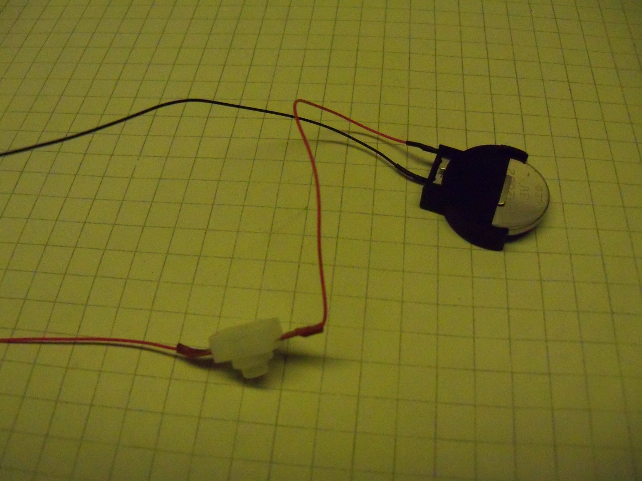
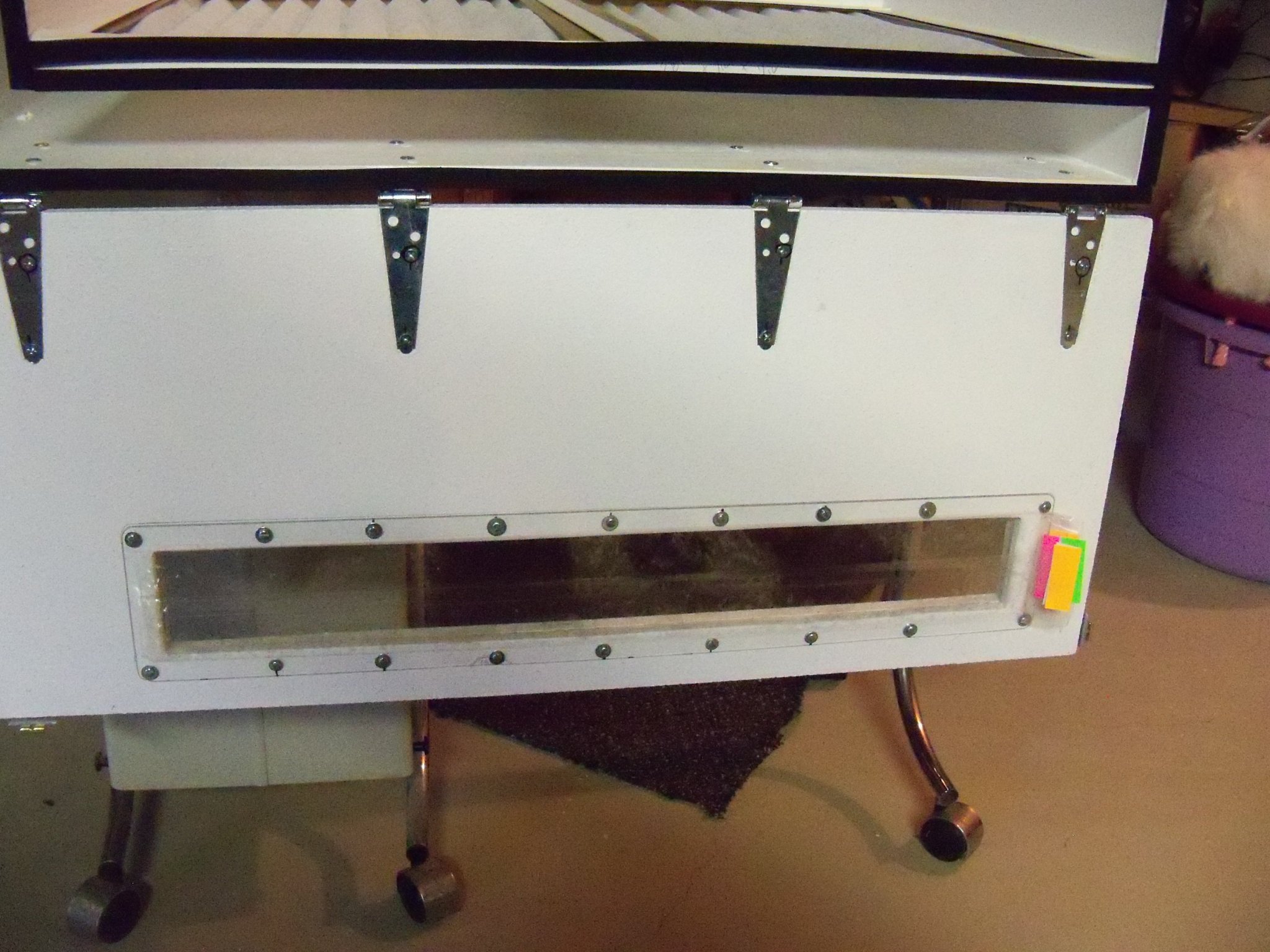
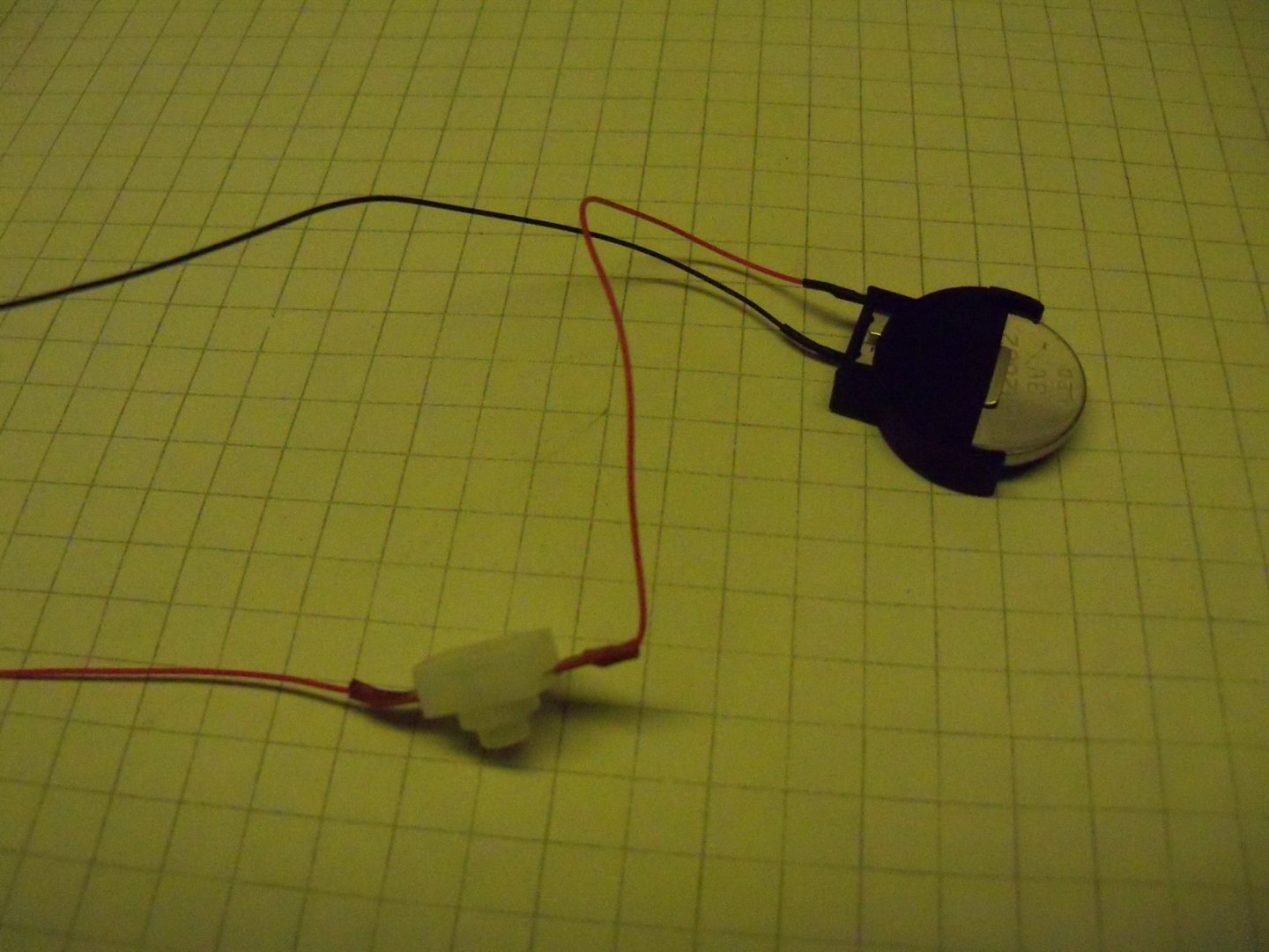
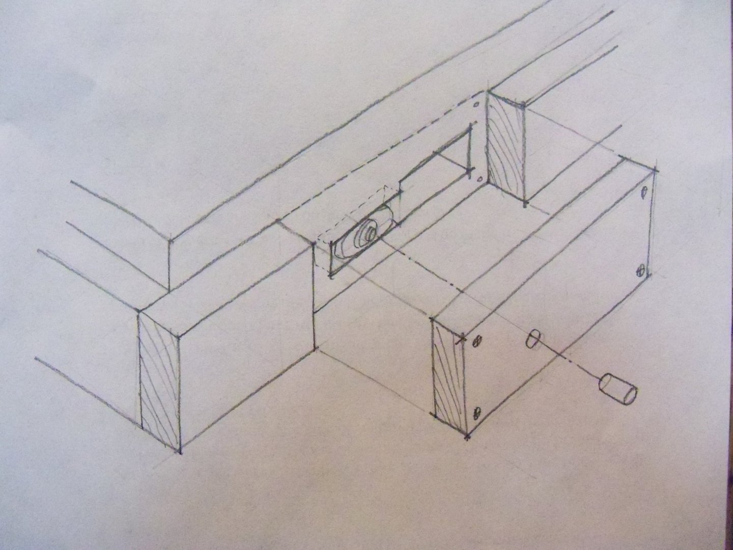
Time for some more thought on making the base board. The top surface with the launching ways has been worked out to my satisfaction, but I need to figure out how to work out some means of getting access to the battery clip and on/off switch without having to turn the entire case upside down. I have decided that the oak board itself is just wide enough to accommodate the ships spars so I won’t be able to cut a ¼” wide rabbet all around it for the Plexiglas cover as I had originally envisioned. This leaves me with adding a strip around the board to form a ledge for it instead. The length of the base is a bit overlong and also needs to be trimmed down, but due to having our old waterbed frame leaning on both my table saw and radial arm saw waiting to be sold, they will not be available for the tasks of cutting it to length or ripping the oak trim strip. As you can see below, it’s not the easiest obstacle to move aside. As far as cutting the oak board to length, I guess that I will just make a very careful cut with my band saw and clean it up with a hand plane and a bit of sanding. As far as the trim goes maybe a trip to the a wood supplier is in order. While a flat ¼” thick (the thickness of the Plexiglas) lattice type molding is what I would prefer, something else may work as well. Here is a photo of the battery clip and the push-button switch components. (Those are ¼” squares to give you a size reference.) I sketched up a diagram of what should work for the battery and switch that’s shown below here. A hollowed out recess in the front edge of the board will be needed for the battery holder and the switch that will be hidden behind a short removable section of the molding. The battery holder really has a very tight grip on the battery requiring me to be able to pull it outside the recess to handle it with both hands. The switch is a different problem altogether since I don’t want to unscrew the section of molding every time I want to switch it on or off. As you can see by the sketch there will be another recess for the switch module, but it will be a tighter fit and it will be held in place with some adhesive. Some routing will also be needed to accommodate the connecting wires. A hole will be drilled through the molding to line up with that switch and a somewhat tight fit length of doweling will project slightly from the surface of the molding. When in place the switch can then be pressed by depressing the doweling without removing the trim section. At least that is the plan, so we’ll see how well that works out.
-
I have had the Craftsman version of that tool for years. The biggest difference between the two tools is that mine is cordless with a rechargeable lithium ion battery. It has that offset in the tool sanding and cutting blades that lets you get in real close. It's a very handy feature that remodelers find very useful for under cutting trim mouldings to install new flooring, since the tool itself can literally get flush with floor to make the cut.
-
I agree Joe, as I bought the very same saw from our local Wood Crafter shop earlier this year. It makes a very fine cut and even people with limited strength like me will find that very little effort is needed to make a cut.
-
That's a nice way to both get rid of your excess materials and at the same time get the books into the hands of someone who can appreciate them rather than just going into to a landfill.
-
Belay Pins
BETAQDAVE replied to shipman's topic in Discussion for a Ship's Deck Furniture, Guns, boats and other Fittings
I find it quite interesting to learn the reasons why and how things were done on a ship the way that they were. I'm sure that a lot of us here without any actual sailing experience can learn a lot from those that have. All of that knowledge can only help to improve our models. -
Bad news guys, I am afraid that Doris will no longer continue with her presentation of her modeling on our site. I went to the modelforum.cz to view her Royal Katherine build log and found a quote (July 14, 2019) where she has said as much. Apparently she was expressing her frustration there at having to repeatedly respond to the same questions over and over even though she had provided many detailed photo tutorials previously. She is apparently on several different modeling forum sites at this time and wanted to cut down on the time spent on them to devote more of her time to actually working on her modeling projects. Personally, I think that she is looking for more guidance for her from the sites. Unfortunately for her, she herself seems to be the authority on the subject and there are few out there that know more about the subject than her. However if you want to continue following her work, (with the availability of the translation programs) just go to the modelform.cz website and you can follow her there. I am saddened by this news as my wife and I can't help but appreciate her artistry and find that I continue using some of her techniques. Still, I wish her continued success on her modeling.
- 1,035 replies
-
- 6
-

-
- royal katherine
- ship of the line
- (and 1 more)
-
Mini Lathe recommendations?
BETAQDAVE replied to jfinan's topic in Modeling tools and Workshop Equipment
Rather than a drill, I just used my drill press set up as shown below. I used a drill gauge to hold the lower end of a slightly oversized dowel in place and chucked the upper end in the drill press. That's how I formed all the masts and gaffs for my MS Phantom. Worked like a charm for me and I didn't need to buy another power tool.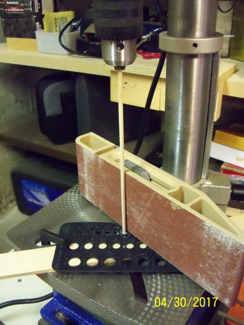
- 75 replies
-
- 12
-
-
Jim, this particular painting brings to my mind the old phrase "See how she scoons." Once said to be the origin of the name schooner. Scoon was an old time word meaning to skip across the water. I think that most of your paintings seem to bring out an emotional response in the viewer, as this one does for me. Keep it up!
-
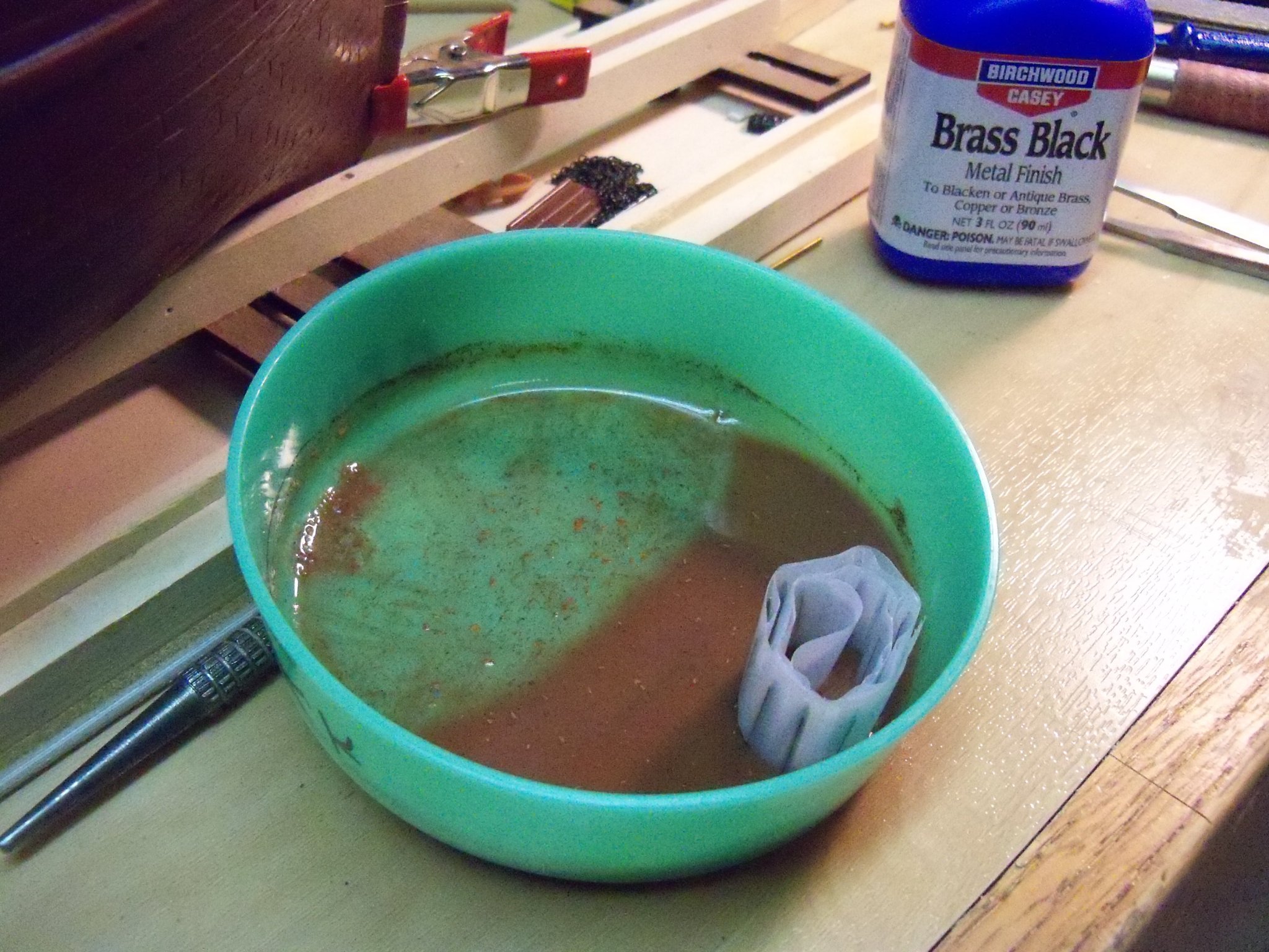
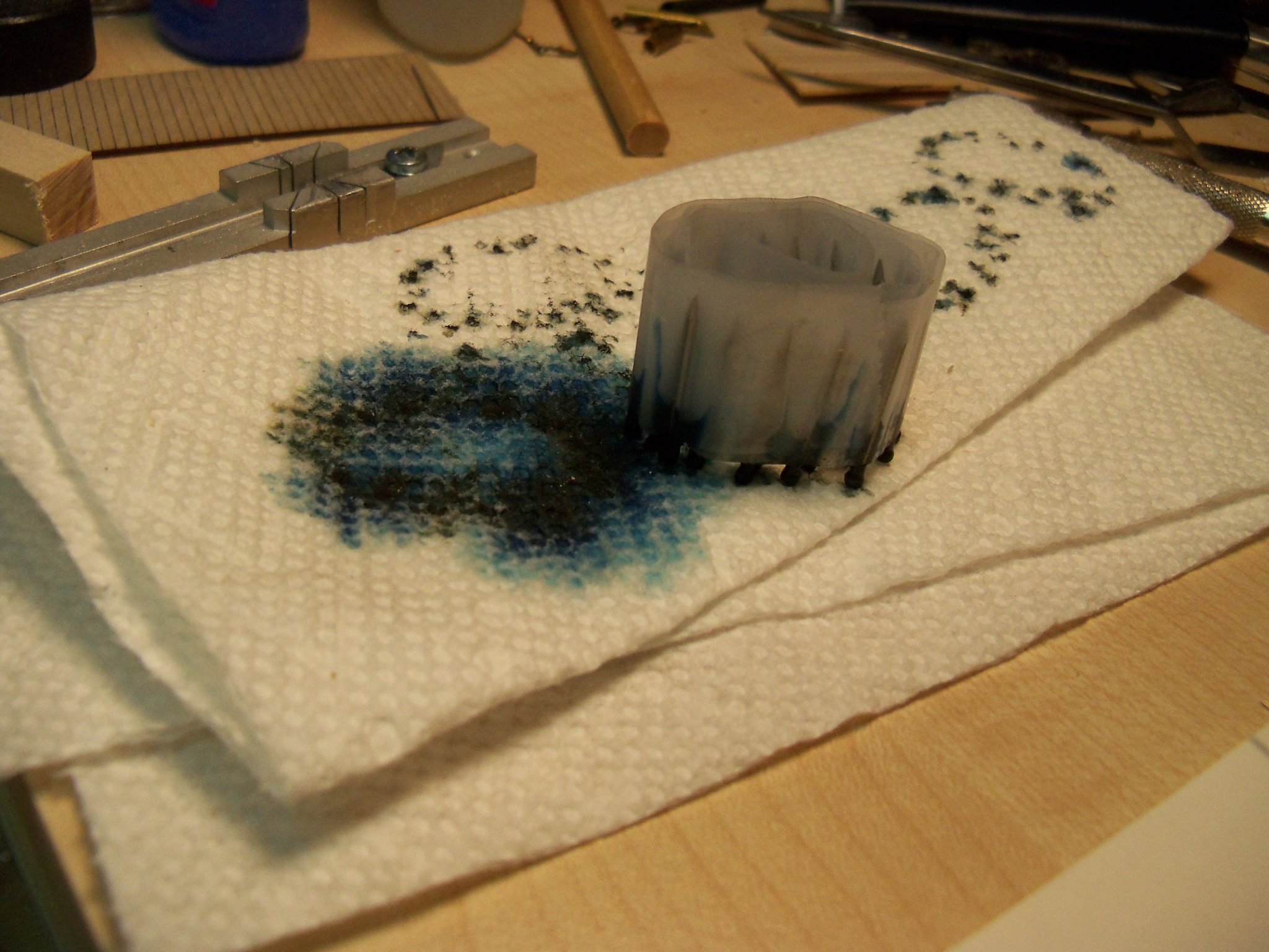
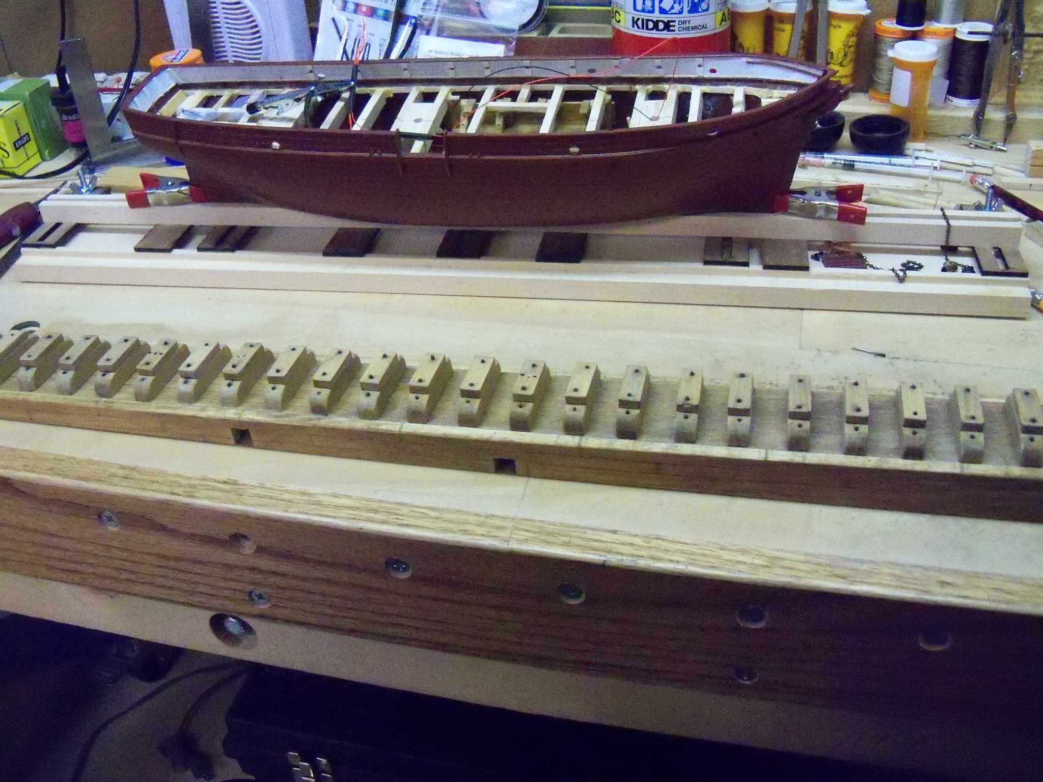
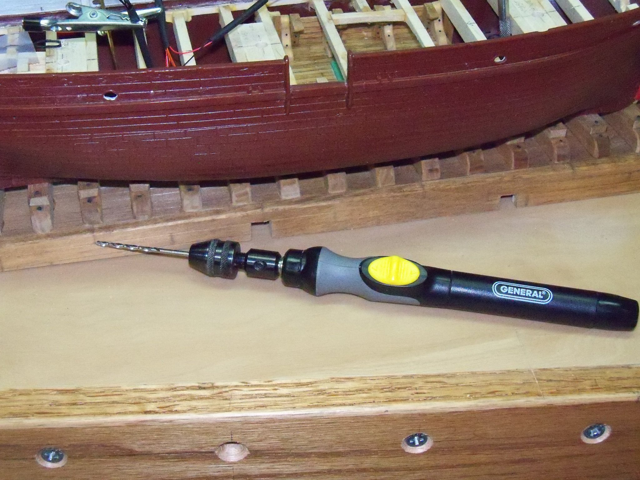
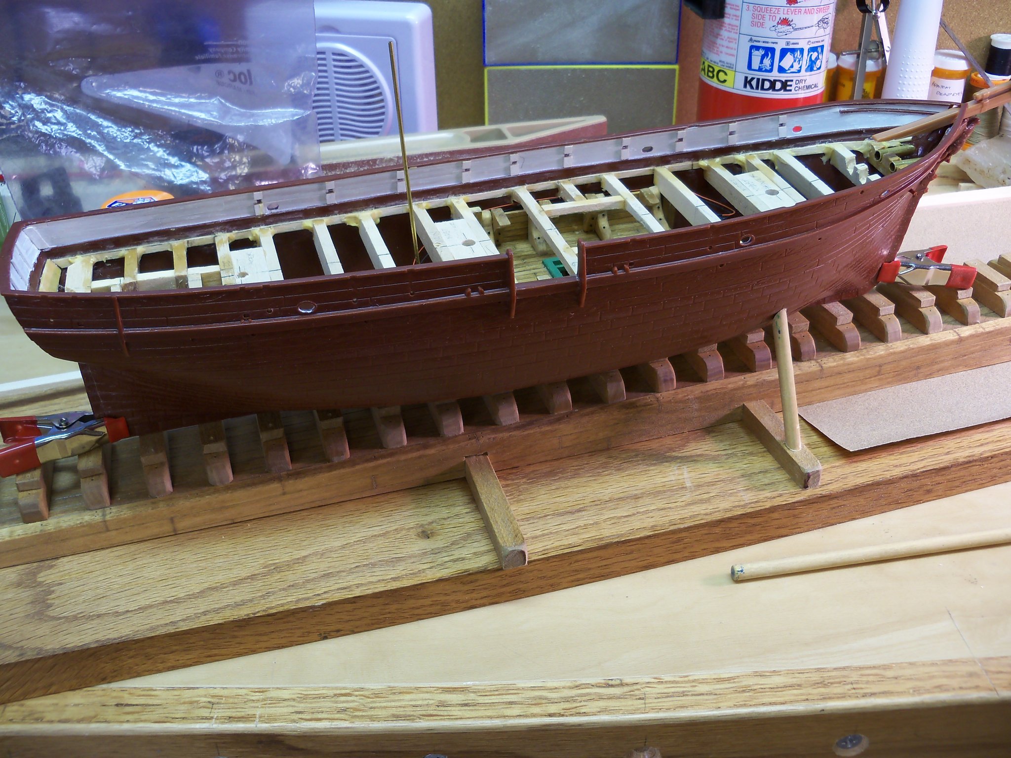
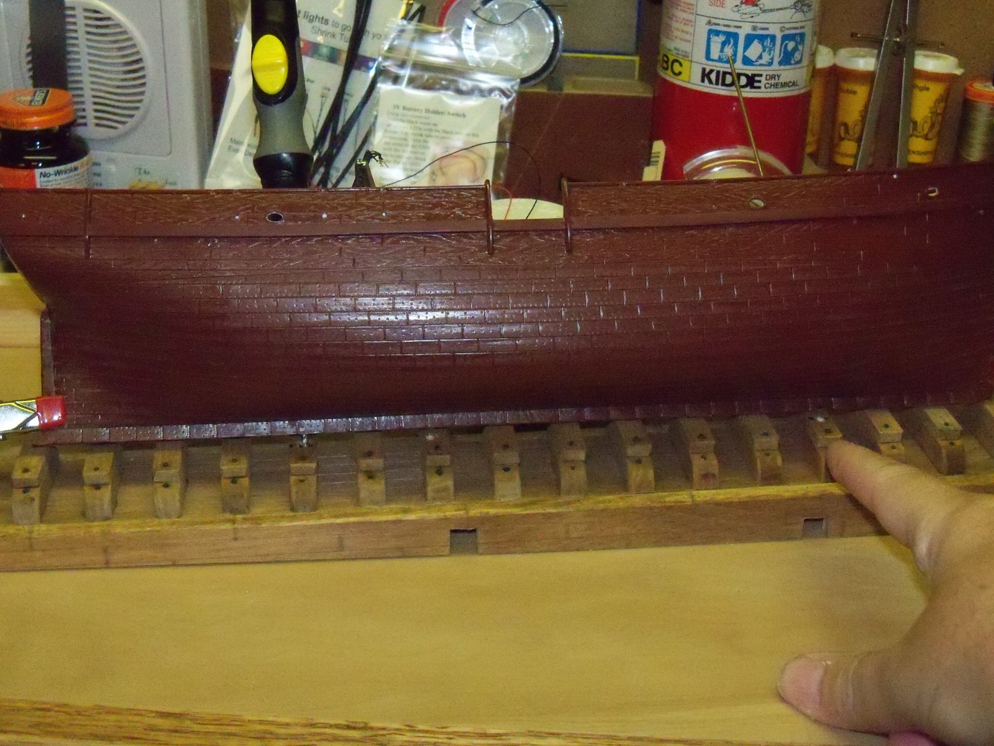
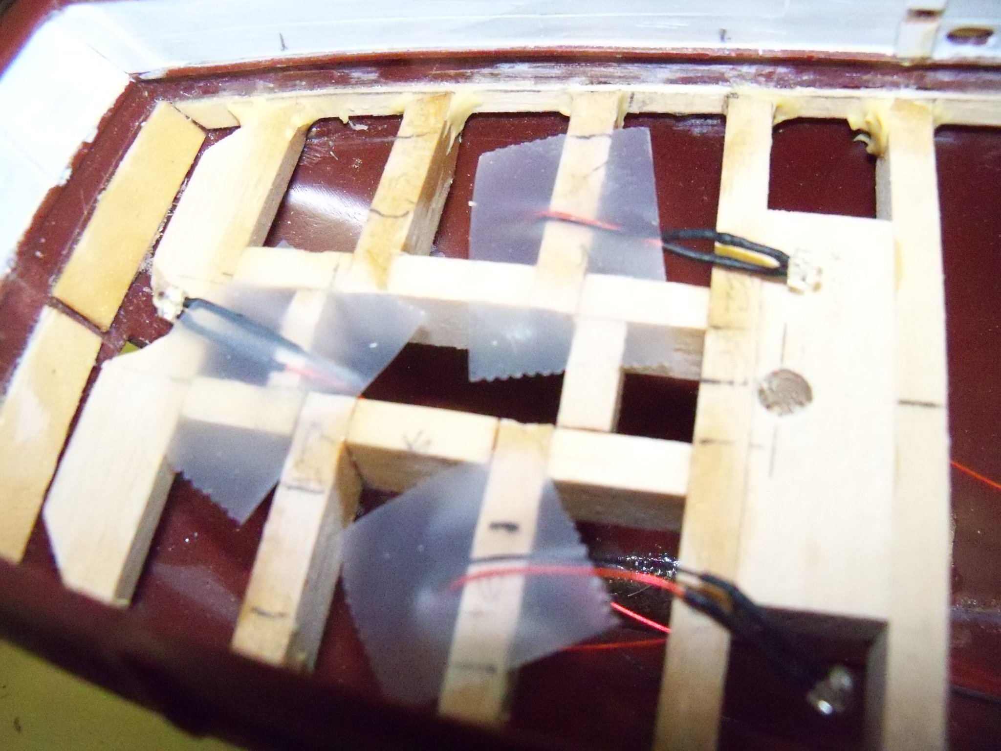
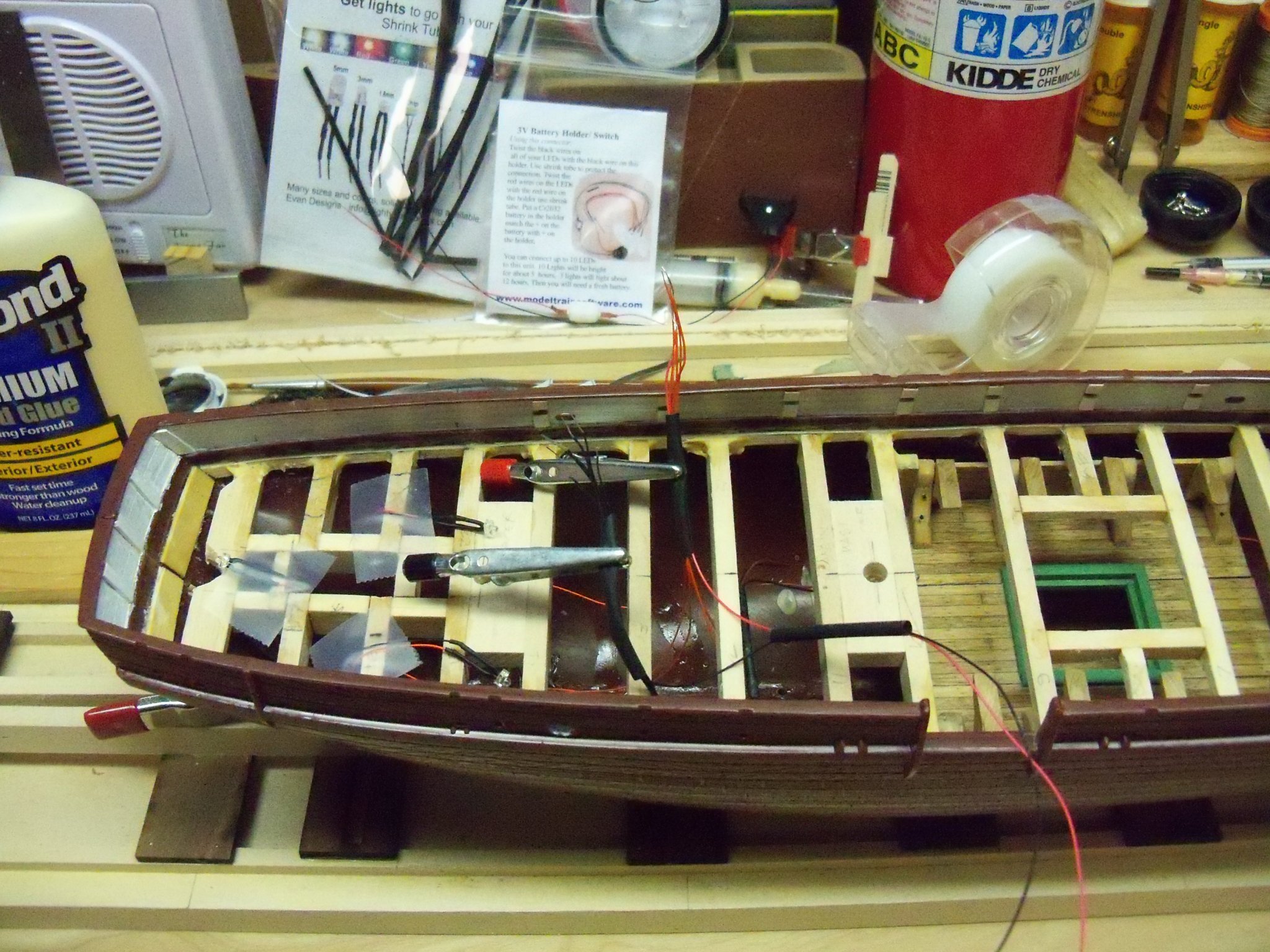
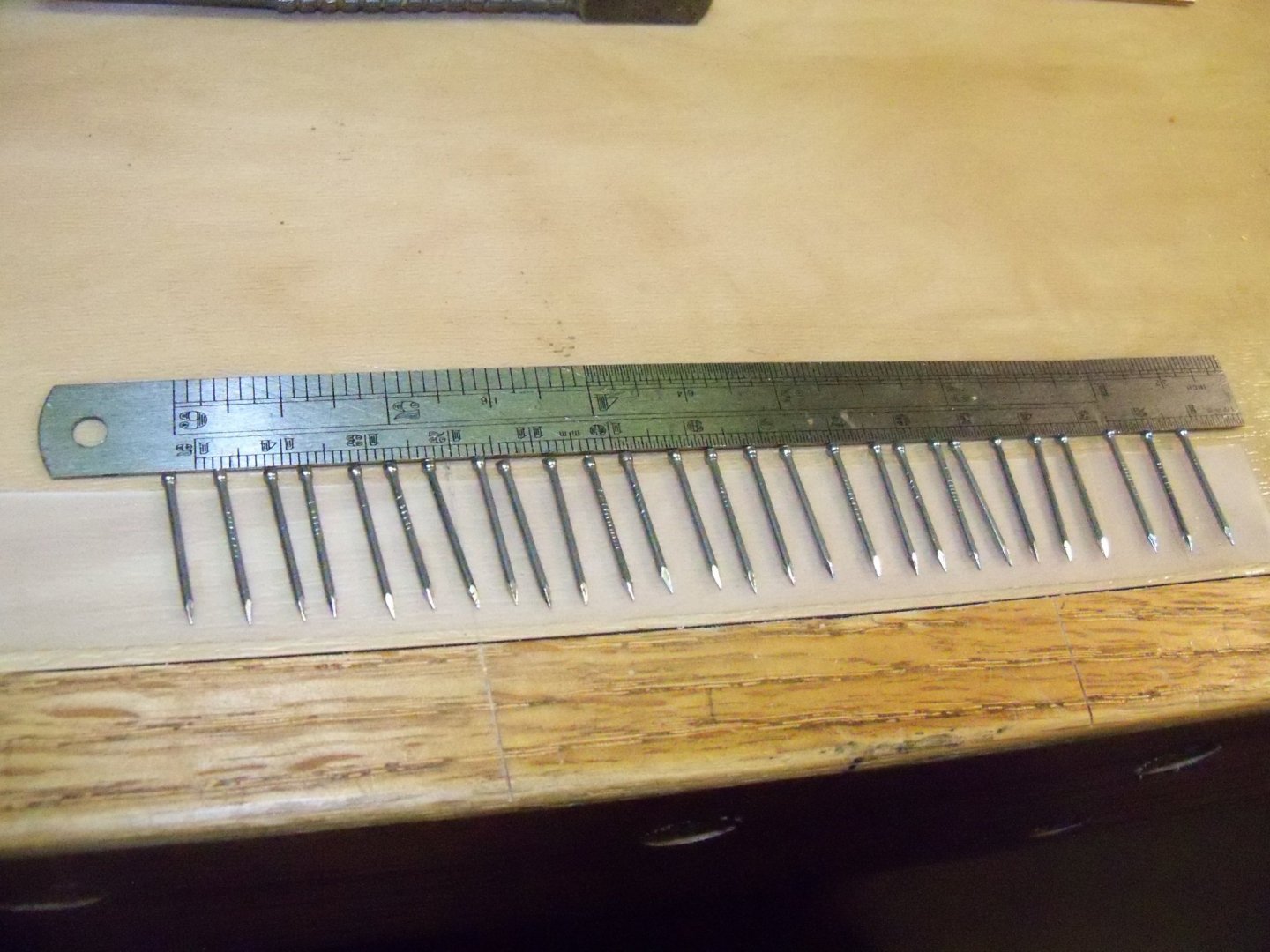
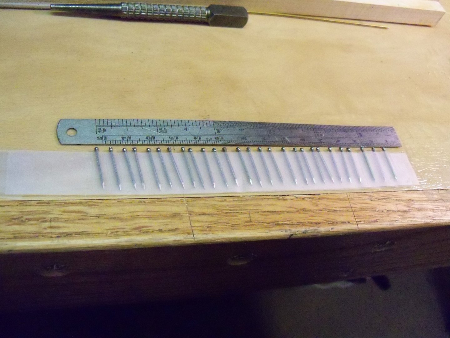
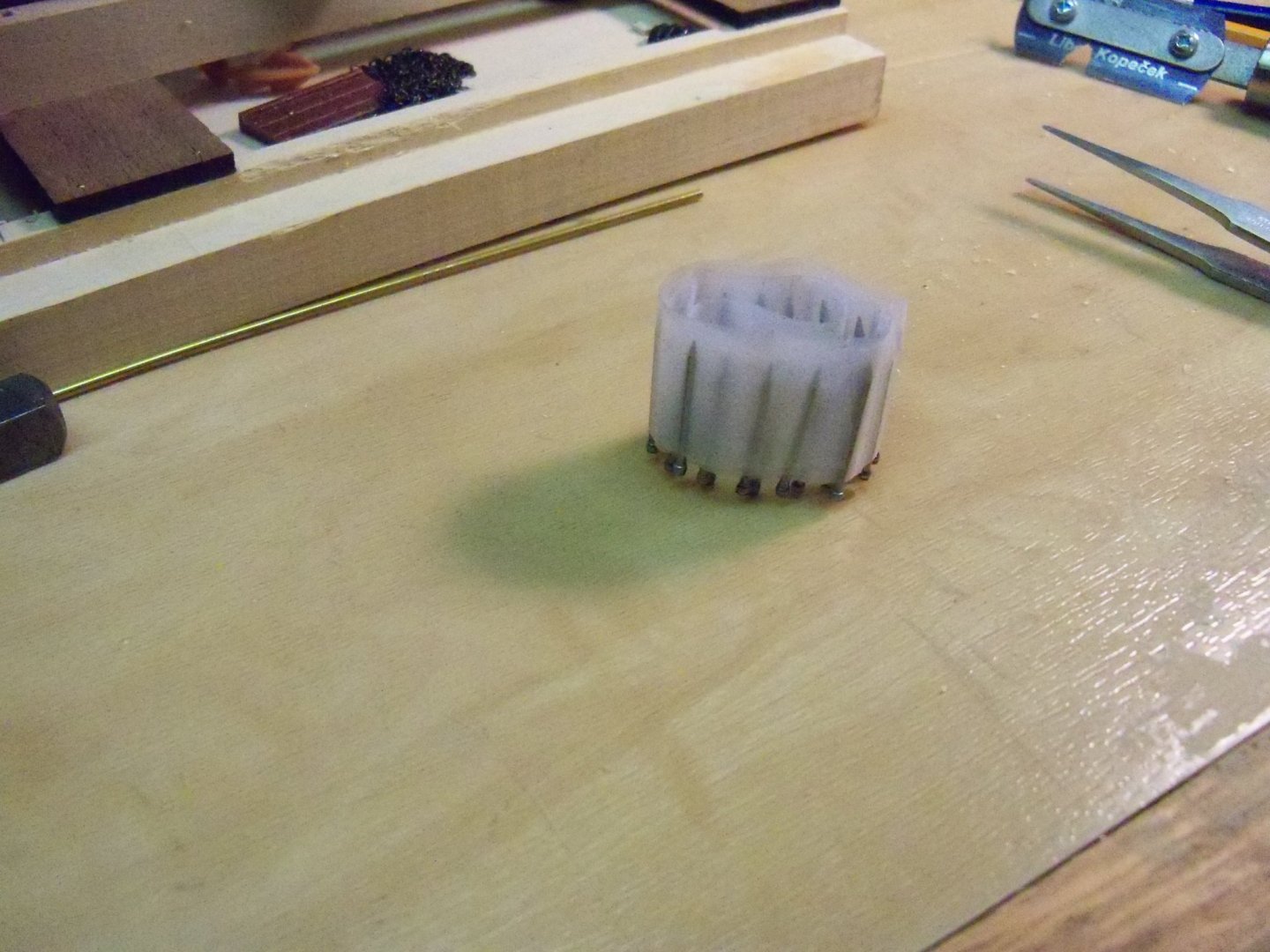
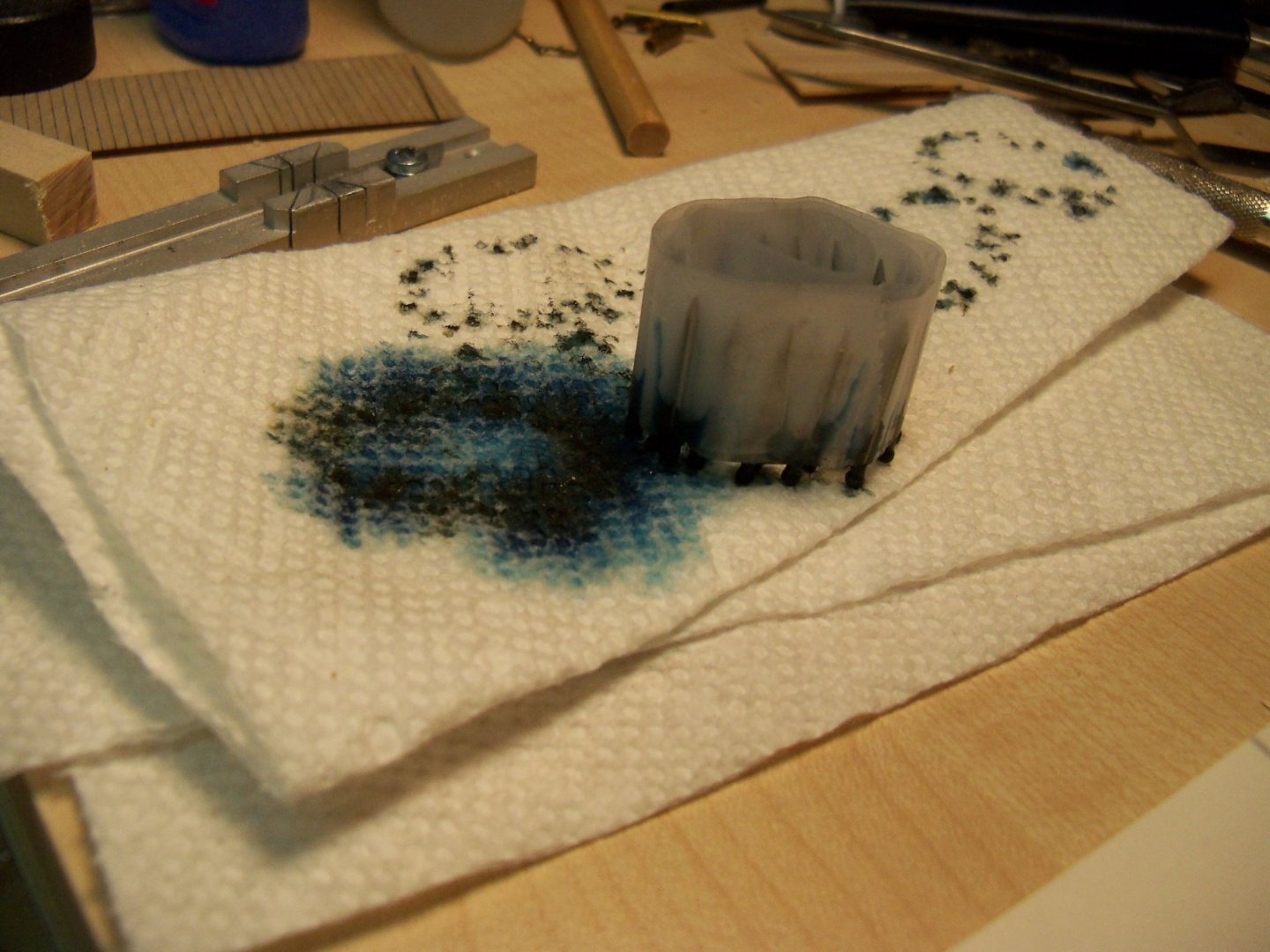
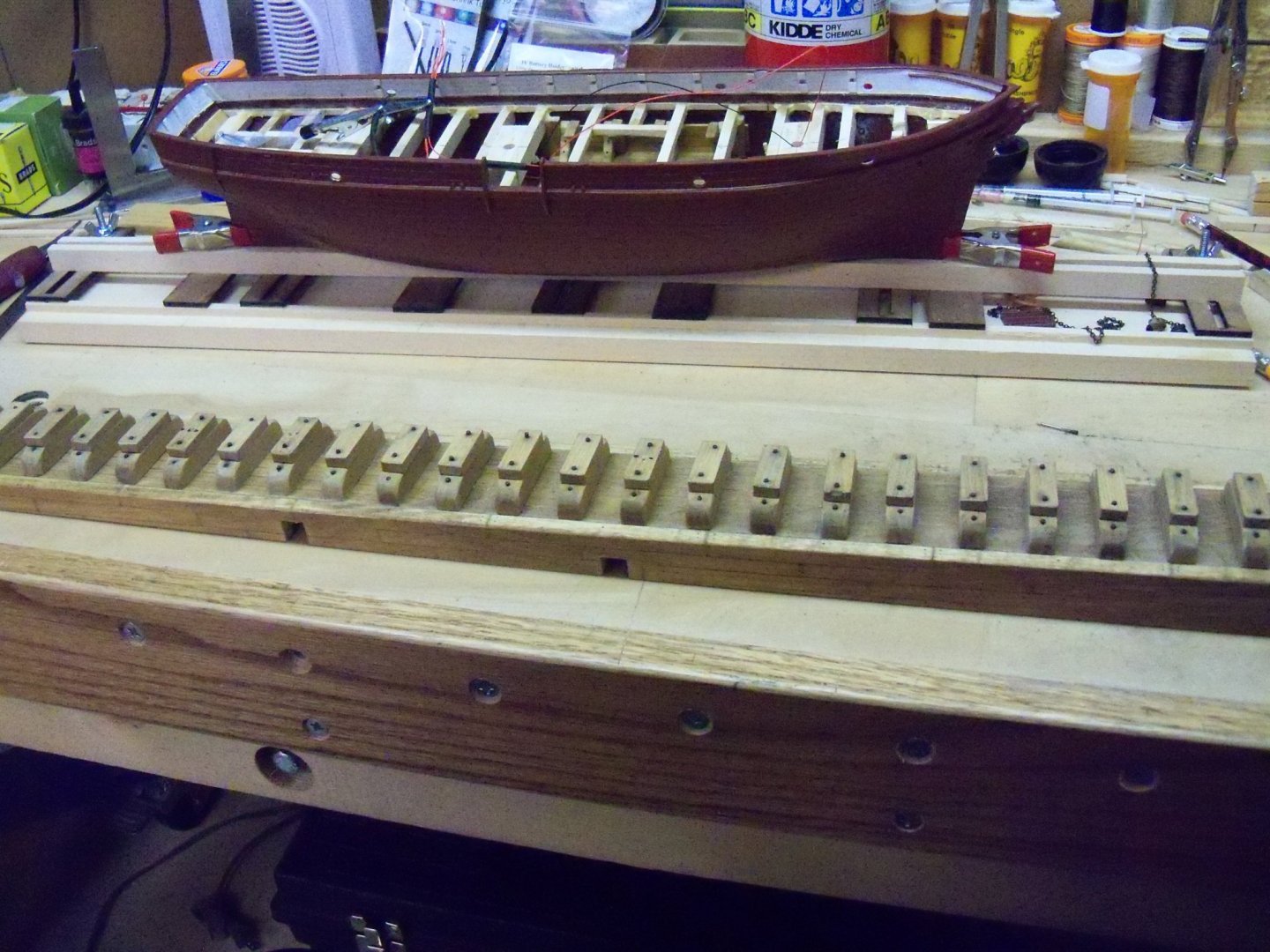
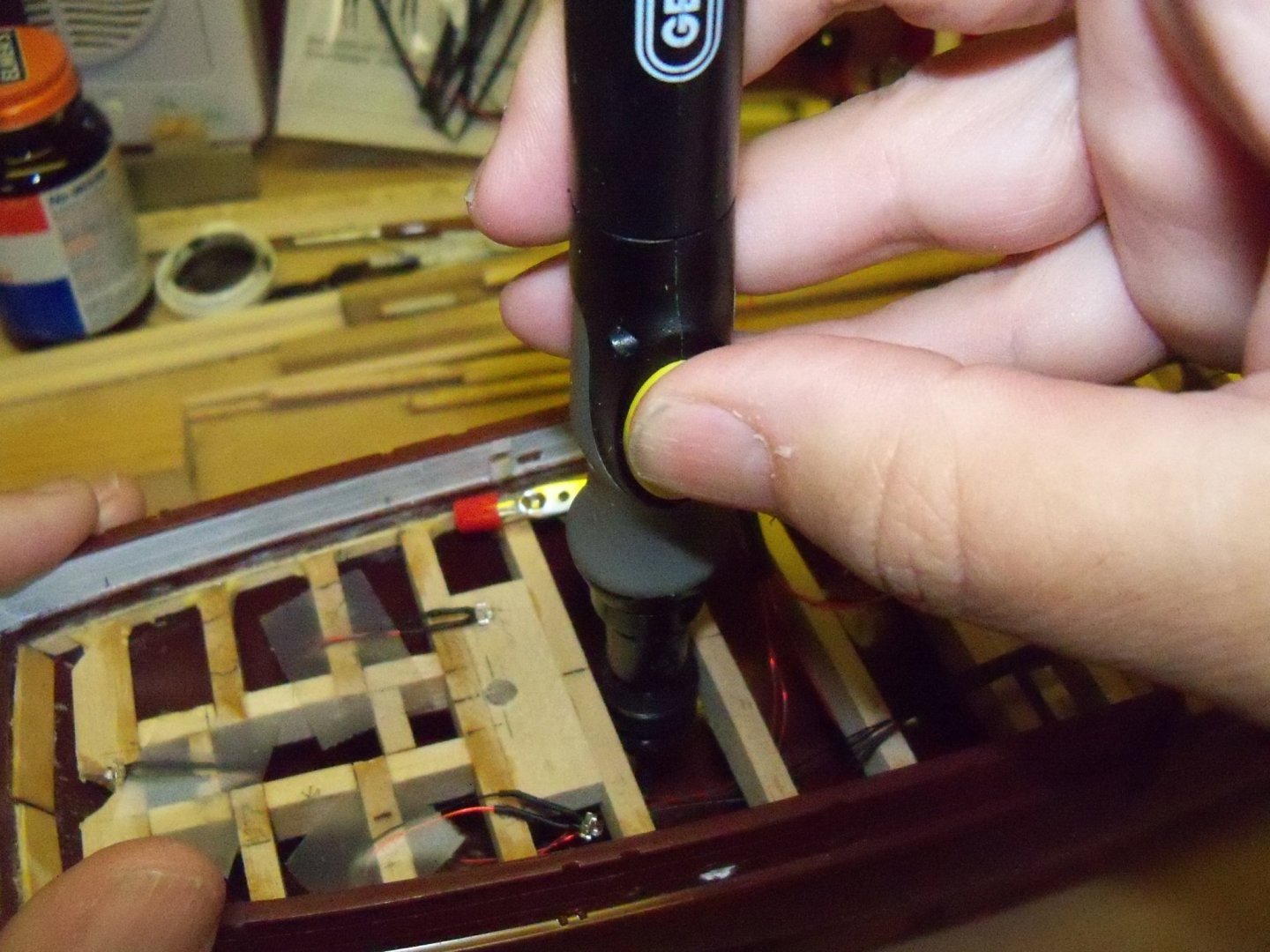
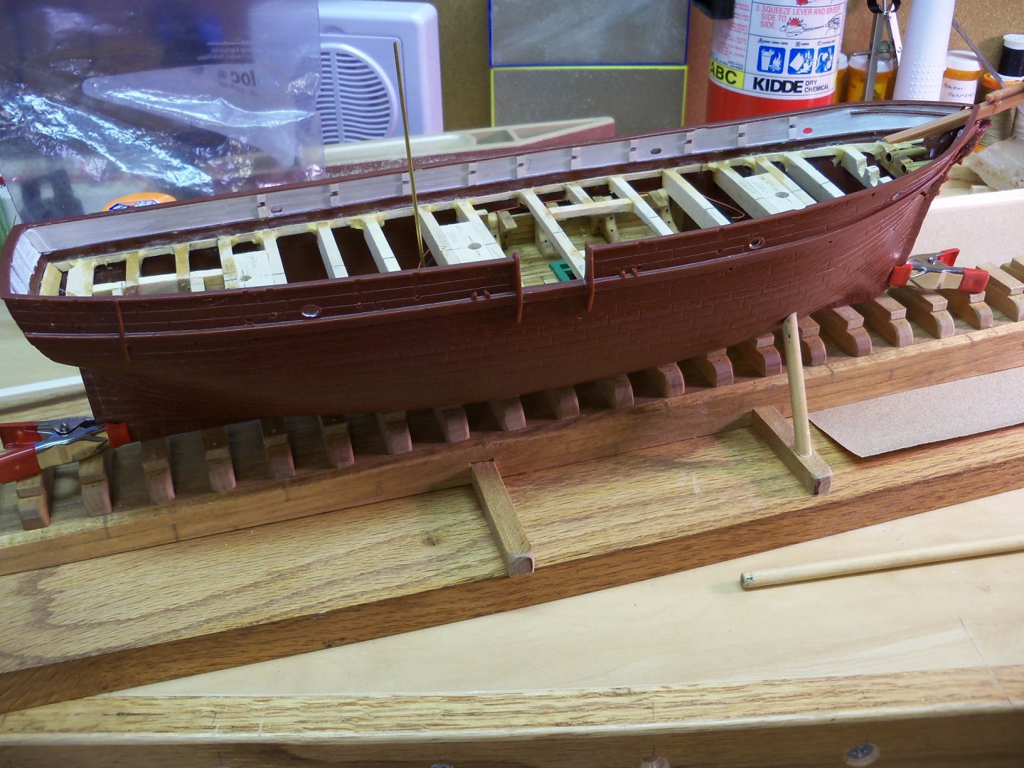
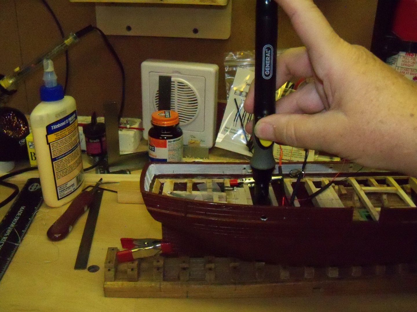
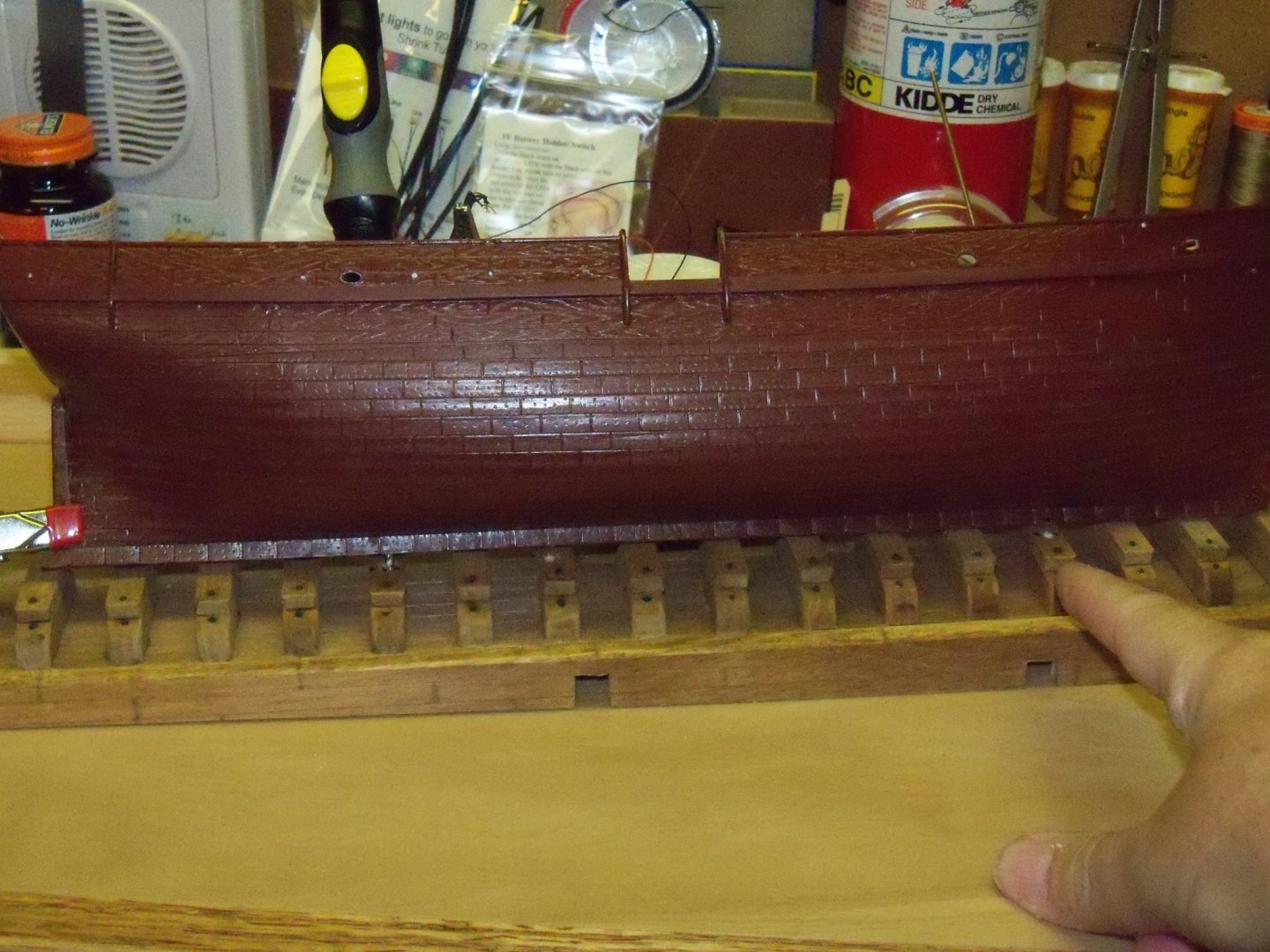
Well, I guess that I was not kidding about the time involved to get back to this ship. The spray booth project ended up taking much longer than I thought and then holiday projects came up, but now I can finally get back to it. This posting is a bit out of order as I needed to stage some of the illustrations after the fact but this is the gist of it. Working once again on the launching ways, I finished drilling the rest of the holes for the bolts in the support blocks and gluing down several that came loose when being drilled. The brads representing those bolts needed to be blackened, but since the only part that would remain visible was the heads, I thought why blacken the whole brad? Using a length of scotch tape laid down sticky side up flat on the bench, the brads were stuck in place with just a small portion of the head projecting beyond the edge of the tape. Then another piece of tape was stretched out sticky side down over the first strip. The next step was to form the strip into a coil as shown below. Using a plastic dish with some previously used brass black that had a bit of fresh mixture added to it, the coil was set into the dish with the brad heads down as shown and set aside for about five minutes for it to work its magic. Removing the coil from the mix, it was set on a paper towel to soak up the excess and let it sit overnight to completely dry out. The next day, the remaining brads were pressed down with a nail set into the drilled holes. A small hammer and the nail set were then used to set the brads until the head was still just visible. So the ramp is ready to be drilled for the mounting bolts. Way back on post #42 I installed two LED lights for both ends of the open hatch and drilled a hole in the hull for the wiring to run to the switch and battery components. Changing my approach now to this problem, I decided to run the wires through the keel and hull support blocks rather than the far side of the hull so it would be less visible. So, I’ll just fill-in that hole in the hull. At this point I discovered that the mounting bolt and wiring hole locations through the keel should have been done before the deck beams were installed as it was not possible to get a drill of such a small diameter (the keel is only 9/64” thick) in a long enough length to pass all the way through the ship and through the ramp, but once again hind sight never really helps much. Luckily I had this battery powered screwdriver/drill made by General with a very slim profile with a lot of torque for such a small tool. Inserting my small 3-jaw keyless chuck for a rotary tool with a 1/8” shank into the tool that I picked up from Micro-Mark, I put a 3/32” bit into it and found that I had just enough space for it between several of the beams. With clamps at both ends of the keel for balance the ship was placed on the ways in its approximate final position. I picked the gap between beam numbers 11 and 12 and drilled through the keel for the LED wiring. With a thin brass tube inserted through that hole, the ship was shifted just enough until the tube could line up with the center of one of the support blocks and it was given a light tap to mark the position. Replacing the tube with the drill the hole was extended through the ways. Once the hole was finished, the brass tube was reinserted to hold the ship in its final position. The gap between beams 13 and 14 was sufficient for the drill so it was chosen for the first bolt hole. With a pair of dividers I set the distance from the center of the support block with the wire hole to the center of the closest support block that would line up for the bolt. The dividers were able to transfer that distance to the inside of the hull and the hole was drilled there. Actually drilling the hole was fairly simple as the drill was easy to keep centered since the hull seam made it easy to align the bit and the centerline of the beams helped to align the upper portion of the tool. The fact that there was so little space between the beams also made it easy to stay perpendicular to the keel. For the second bolt hole the technique was somewhat different as the divider couldn’t mark the location inside the hull. I picked the gap between beams 2 and 3, then located the closest support block to that space and marked on the keel where it lined up. Drilling from the outside was a bit more trouble as there was no flat area on the seam to set the drill. So, I filed a flat spot and used an awl to give the drill a place to start. Keeping the thinness of the keel in mind I carefully drilled a hole with a 1/16” bit perpendicular to the keel through to the inside of the hull. Now that there was a hole to guide the larger bit, I enlarged the hole from the inside of the hull with the 3/32” bit. While I was locating the LED for the skylight the decision was made to install LED lights inside the two rear shelter houses. The three of these LEDs were now all temporarily taped in their positions. So, now I will be installing a total of five LEDs to run through one battery and switch. The wires are not long enough to pass through the hull and into the base were the switch and battery will be placed and thus need to be spiced with another section of wire to make up the difference. The splice will remain inside the hull with just the wire extension running into the base. Joining the wires is fairly simple. I just need to gather up all of the black wire leads including the extension wire, twist them together, apply some solder, and slip a section of heat shrink tubing over the joint to protect it. Then all of the red wires need to be joined together similarly. A section of heat shrink tubing will protect the two lead wires where they pass through the keel and base. Once the ship is anchored permanently to the launching ways, the finish connections can be made in the base. For now they will just be taped out of the way.


-
Converting a Backyard Shed into a Model Workshop
BETAQDAVE replied to Hank's topic in Modeling tools and Workshop Equipment
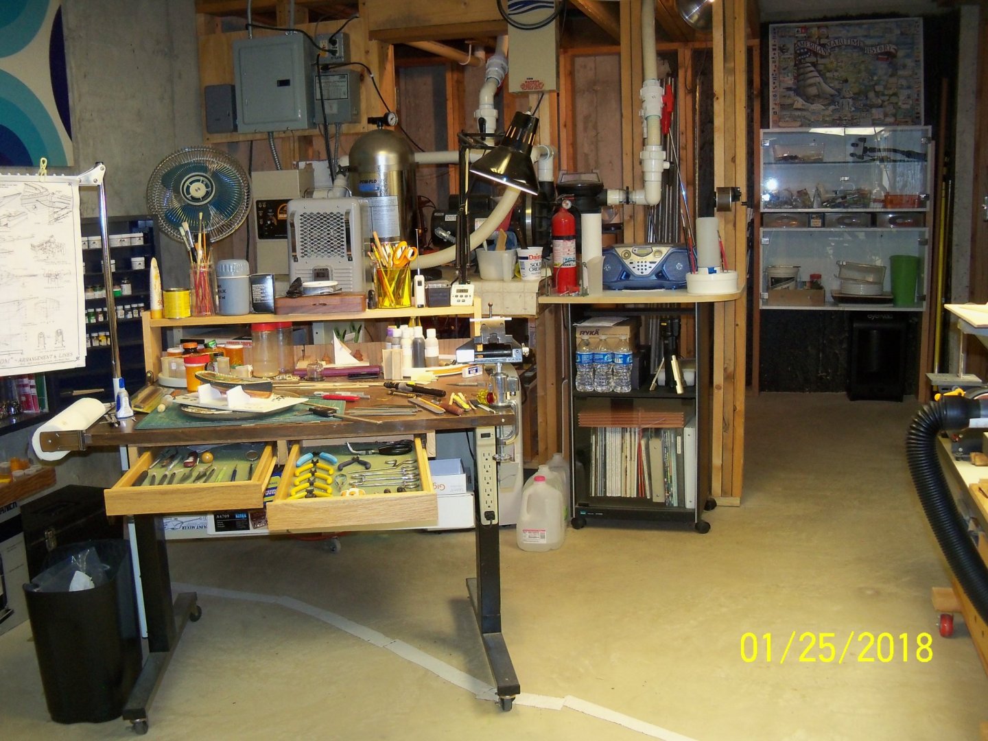
I was reading about your shop remodel and realized that all of my outlets were on the walls except for my main modeling table which has a power strip mounted on the right leg of the bench. I hadn’t thought of doing it on my heavy duty bench until I read Bobs’ remark. So I went down to the shop right away (before I could forget) and installed a power strip on the right side to remedy my omission. I have had problems previously with cords getting in my way, and was surprised that I didn’t think of it myself. I may install one on the left side later if I find the need. Being wheelchair bound, every piece of equipment in my shop is on casters to make it easier to clean the shop when necessary. (And to chase down some of those small items that always seem to dissapear underneath, where I can't reach them!!)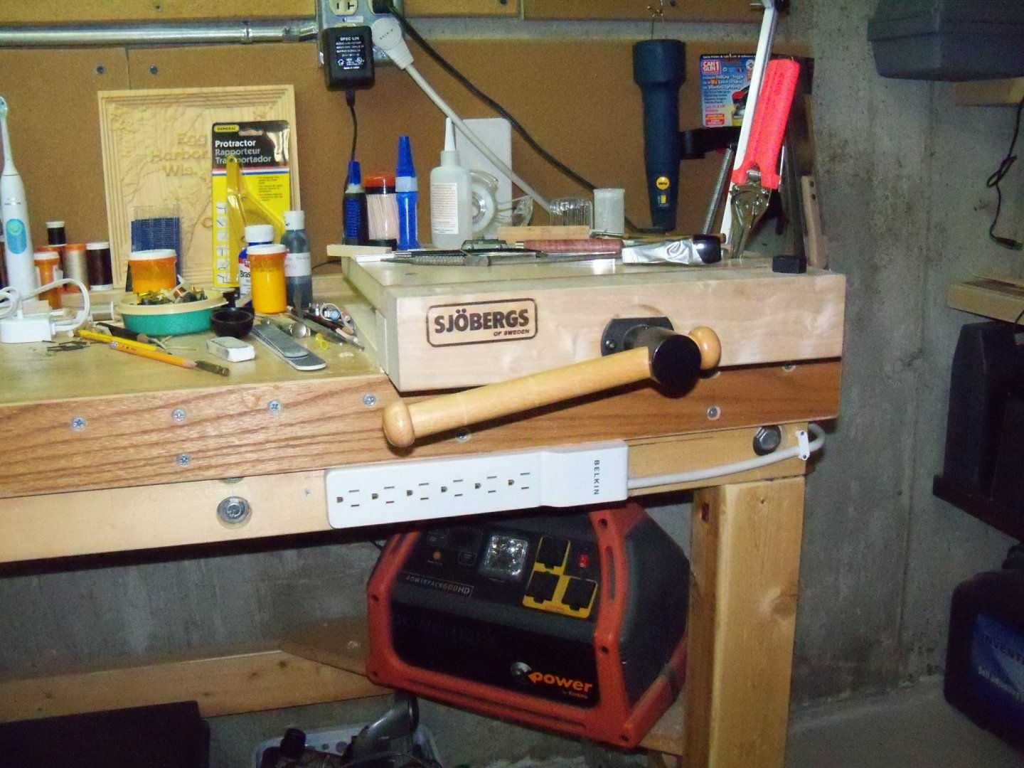
-
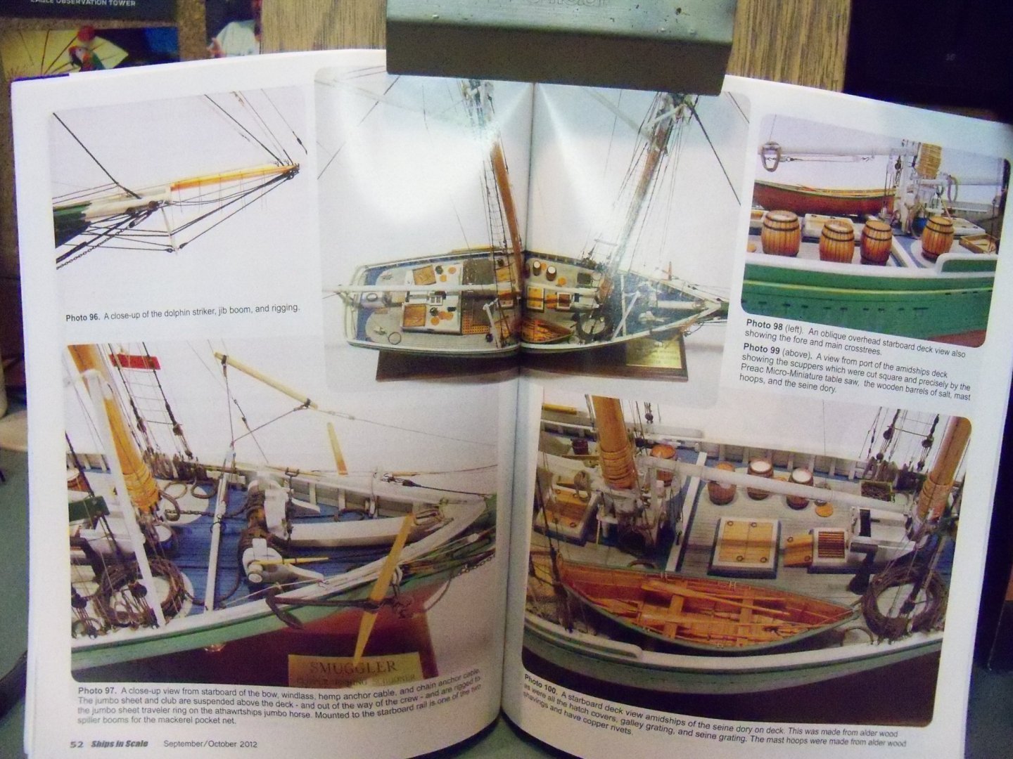
There was a five part article in the now out of print Ships In Scale magazine running from the Jan/Feb 2012 issue to the Sept/Oct issue by Robert N. Steinbrunn where he did a highly modified version of that Smuggler kit from Bluejacket Ship Crafters. I would suggest that you get a hold of those issues that are available from the NRG store on disc or flash drive. If nothing else it will show you just what is possible with this medium. From this shot of the article below you can see some of the remarkable details that he added to this kit that made it a truly museum quality model.
-
Welcome To MSW. And just where do you have enough room to display that monster?
-
Steve One advantage that I can see (having done most of my ships with the bread and butter method) with the POB method would be that you don’t have to constantly try to keep track of station lines to check the fit of the hull profile templates, as the frames do that for you.
-
Welcome to MSW. Lots of inspiration here to help with just about any question you may come up with.
-
Greetings from New Jersey
BETAQDAVE replied to EricWilliamMarshall's topic in New member Introductions
Welcome to MSW. Most of us here started with plastic models in our younger days including me, but I at least went for plastic ships over cars. The complexity of the square riggers drew me that way. I have a little more experience with woodworking than most, as both my father and his father were very much into it and I inherited many of their tools and to a lesser extent their skills. I would suggest that you pick a simple wooden ship model with minimal rigging to allow the use of some of your wood skills and get the feel for working with the miniature size of things. If all goes well you may find yourself hooked on the hobby and be anxious to move on to something a little more challenging. As you yourself have pointed out, this hobby involves a lifelong learning curve, so don't bite off more than you can chew right away or you may loose your interest quickly. -
That's quite impressive but, unfortunately beyond my skill at 1:96 scale.
-
While the detail on your version of this sub is quite spectacular, my father would probably just shudder to see it. In 42 he had to risk the dangerous Atlantic crossing on a troop ship to England. Their convoy only lost one ship, but he was on deck to see it go down. When his trip started he was apprehensive to be sure, but with a little over half of his journey remaining after that, the fear factor really went through the roof. He said he never felt so defenseless in his life.
-
I myself, would be very happy to be able to make either version! Those are great looking hooks, where do you get them?
-
How to use a Circle Cutter by Dan Vadas
BETAQDAVE replied to Dan Vadas's topic in Modeling tools and Workshop Equipment
Yes, there are quite a lot of poor quality tools out there, especially on the WEB. This quote sums up my view of why it persists. “As long as people will accept crap, it will be financially profitable to dispense it.” – Dick Cavett -
Homemade Spray Booth
BETAQDAVE replied to BETAQDAVE's topic in Modeling tools and Workshop Equipment
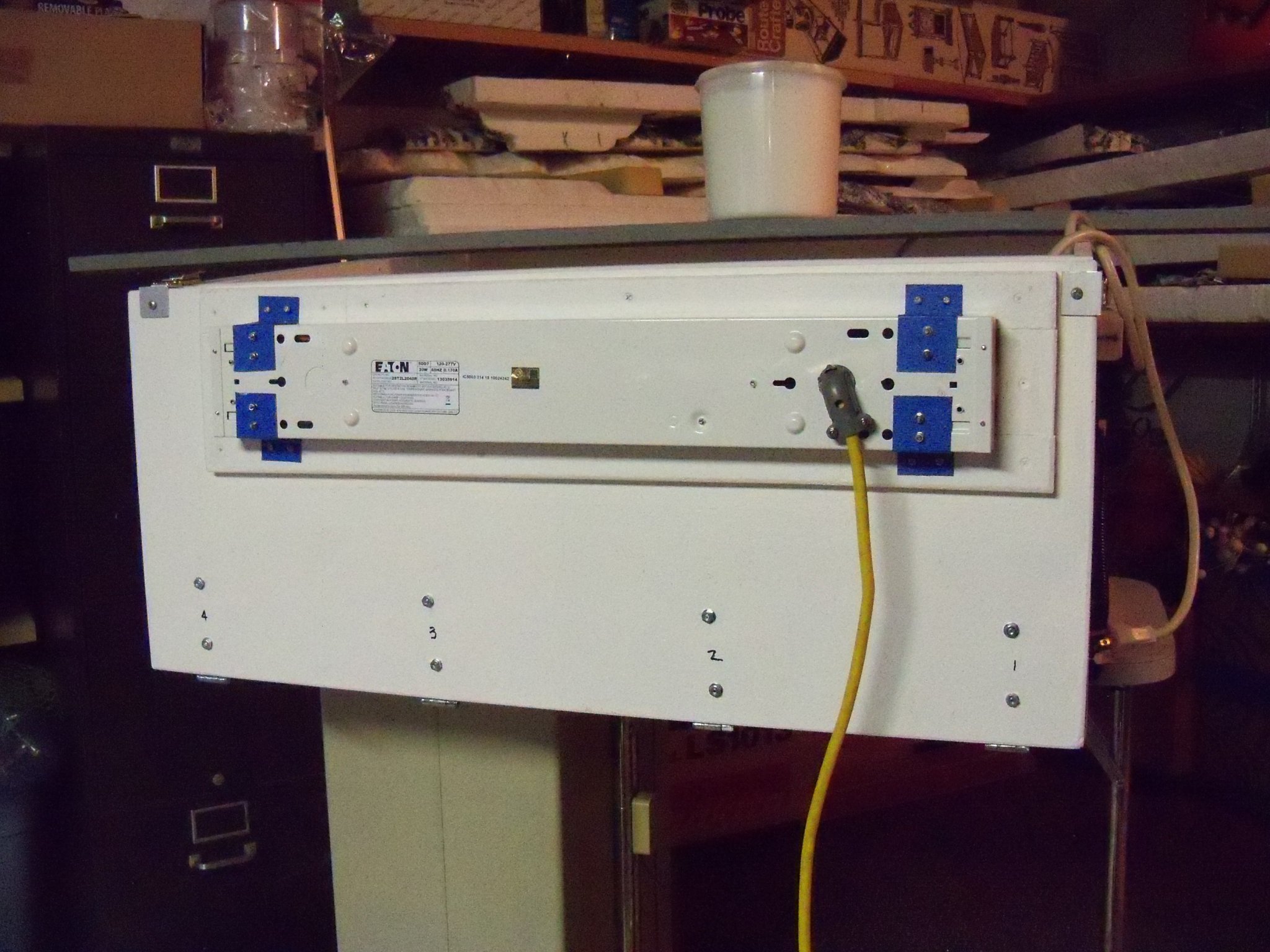
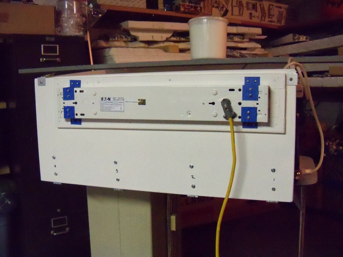
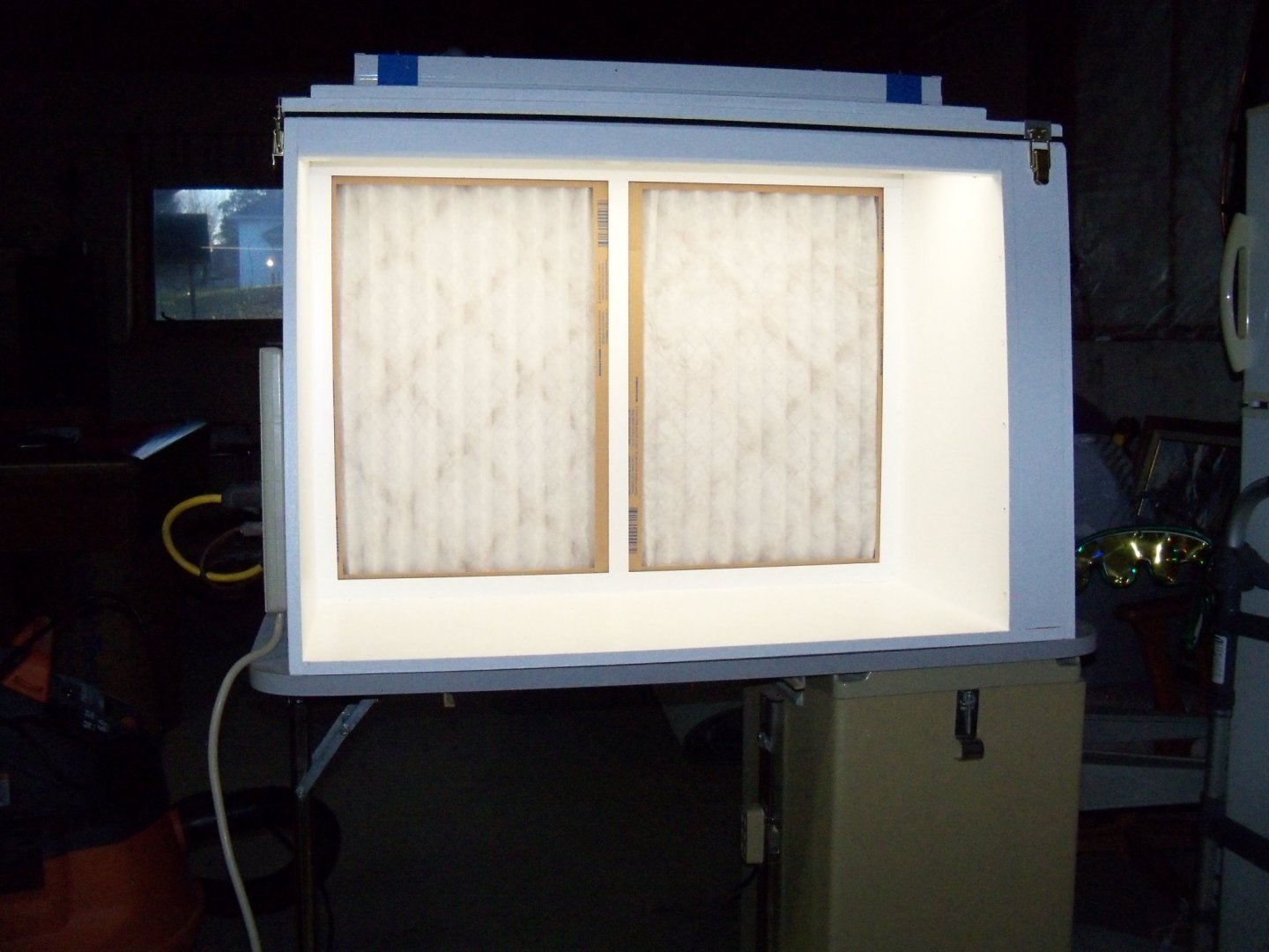
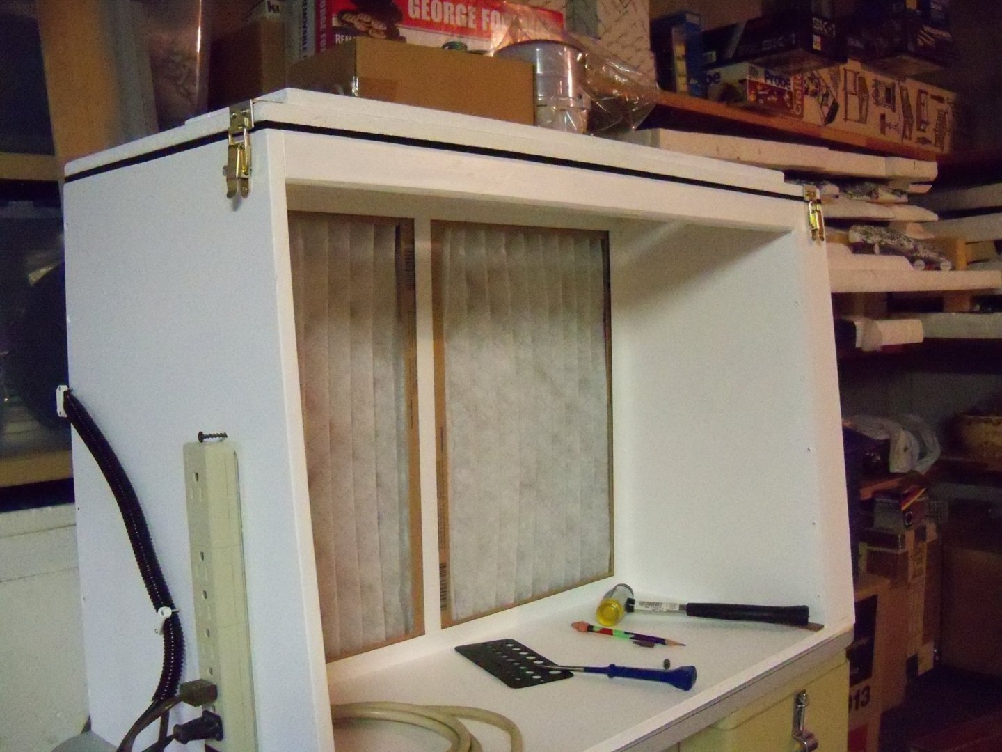
I got back in the shop today to work on the booth once more. First off, I tipped it down onto its back once again with the catches locked, being very careful this time since it is getting a bit top heavy now. Unlatching the top panel, I tipped the top panel open and reattached the Plexiglas window. All the screws were driven in tightly and then backed off about a quarter turn so it could still expand if it had to. The top panel was latched closed now. As I said, the booth is a little tippy in this position, so I placed a board across the far side with a half-gallon container of paint for a counter weight since the added weight of the light would make it more so. Once safely balanced, the light fixture was reattached. So, at this point I thought it was time for the acid test. I tipped the booth upright again, routing the light chord around to the side and plugged it into the power strip. The power strip was plugged in and crossing my fingers, I turned it on. Eureka!! It all worked. There was ample light to work with (as you can see here) and as the fans amped up, the draw proved to be quite satisfactory. So I guess that all that remains to be done now is to decide which rolling cart will be used. I will try using it to see if the height above the floor needs to be lowered for me or not. The cart that it is sitting on right now has the advantage of having storage drawers on one side, but it will be harder to shorten the legs than the other one which has no drawers. I think that I may also need to work out an exhaust duct system, although I plan on wheeling it outside on the driveway to use it. Of course if it’s too cold or raining out that might prove to be a little inconvenient.
-
Homemade Spray Booth
BETAQDAVE replied to BETAQDAVE's topic in Modeling tools and Workshop Equipment
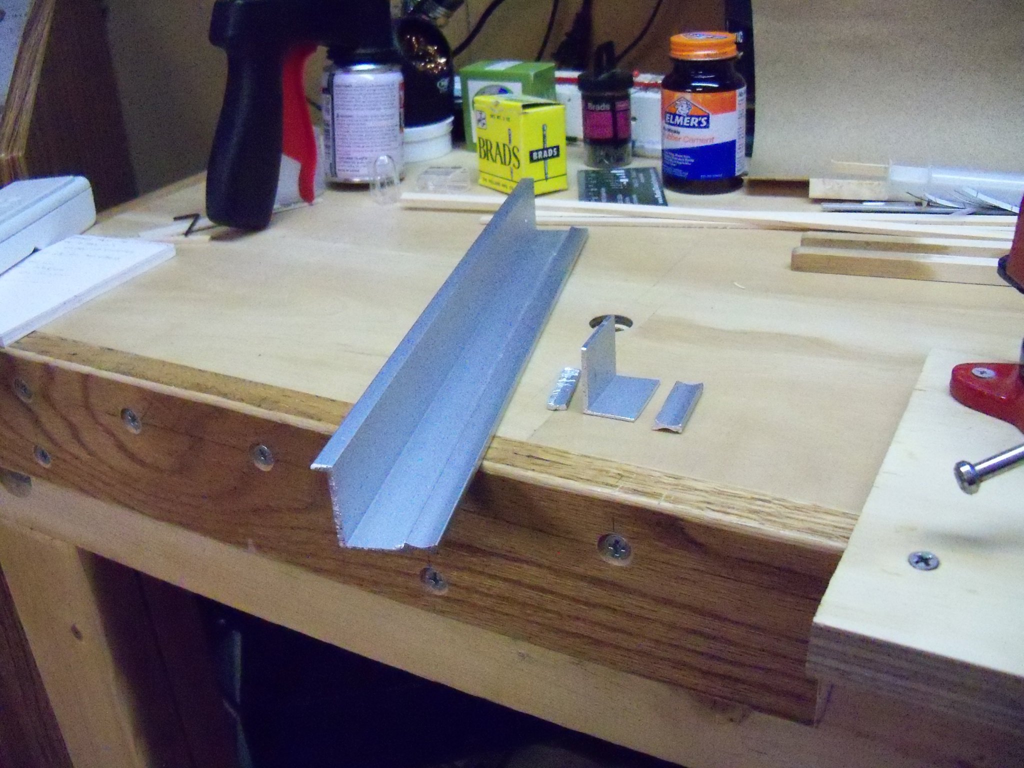
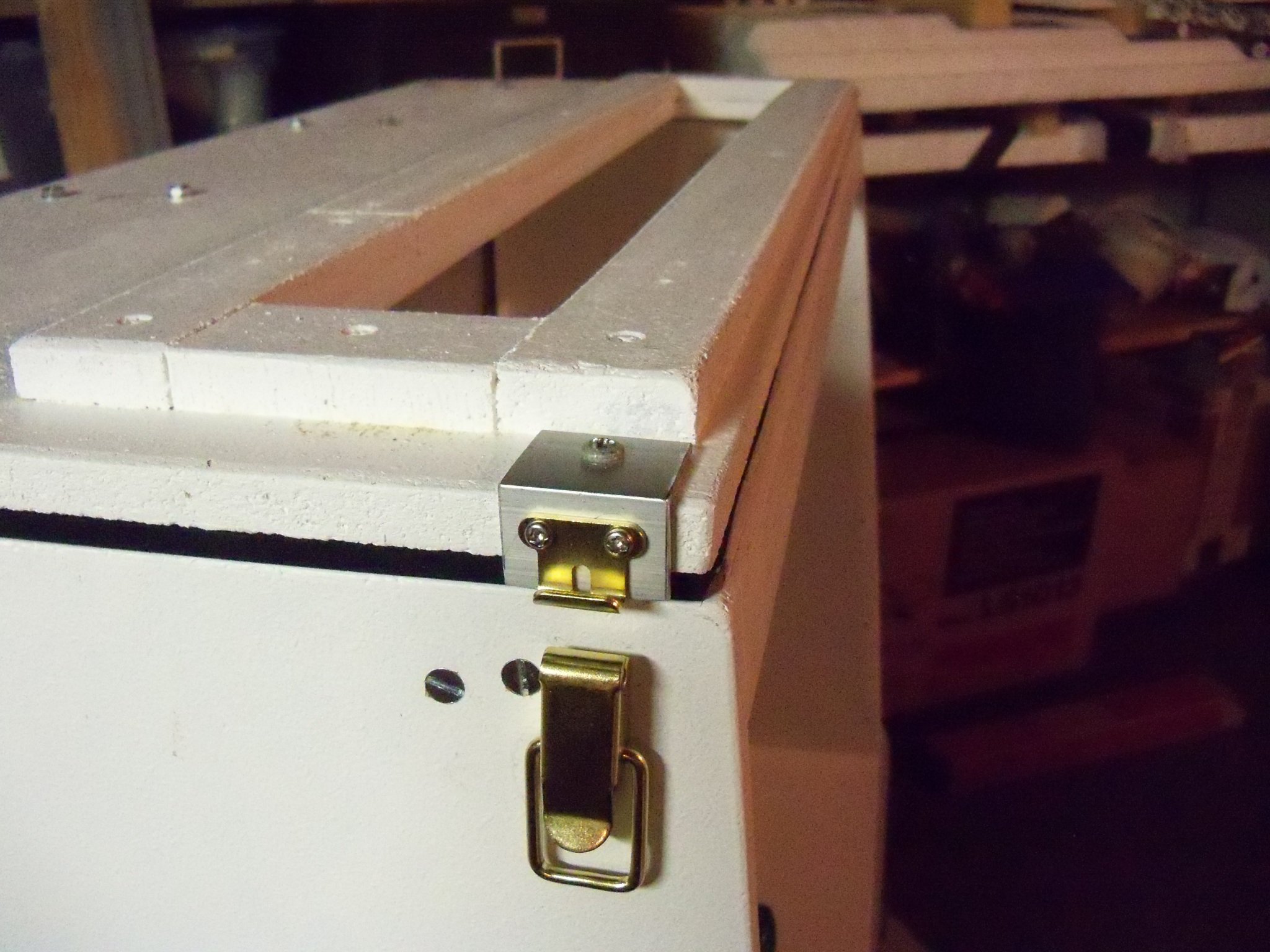
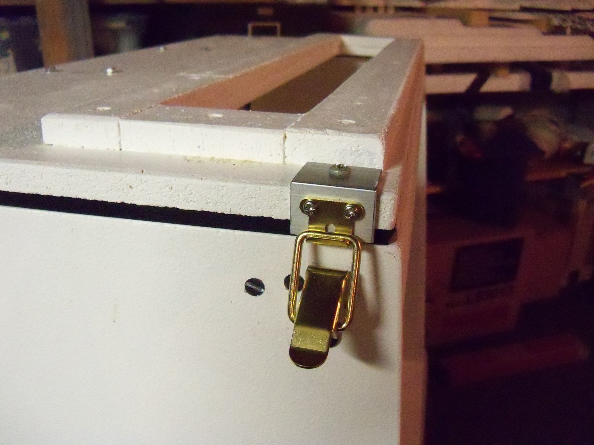
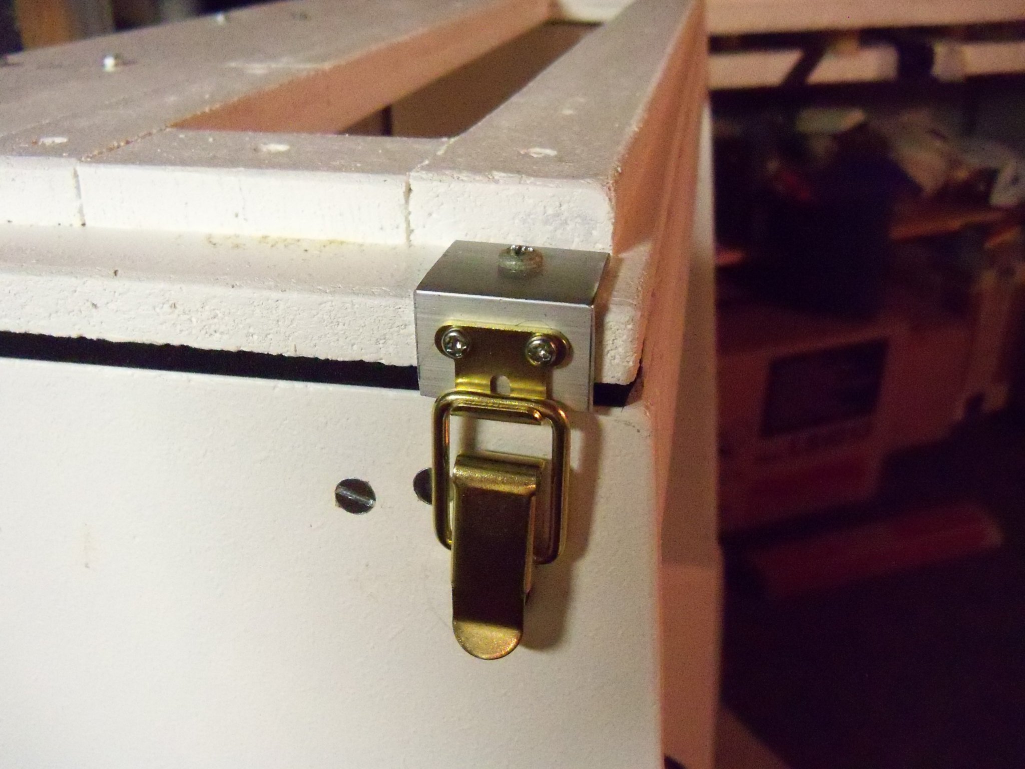
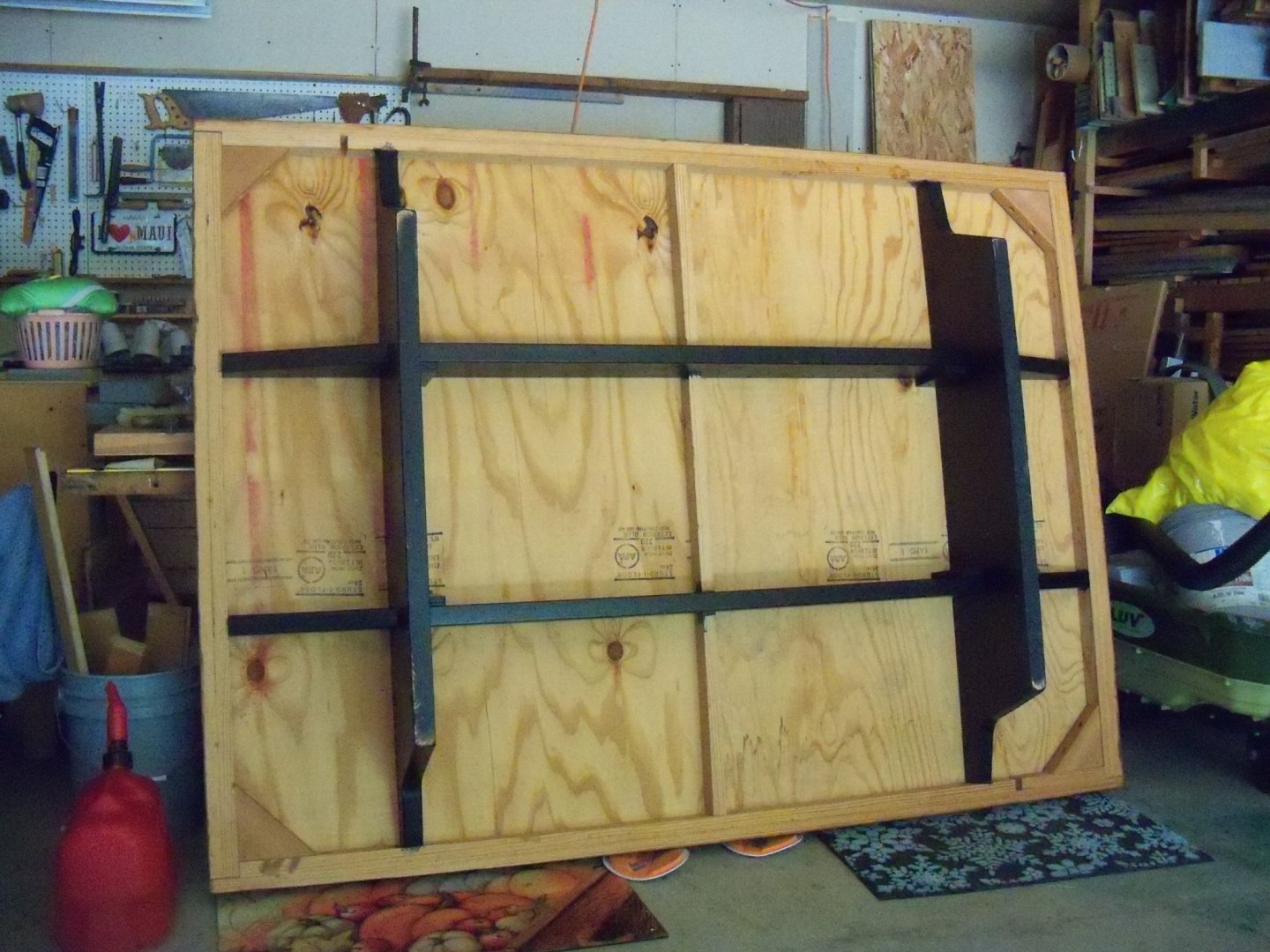
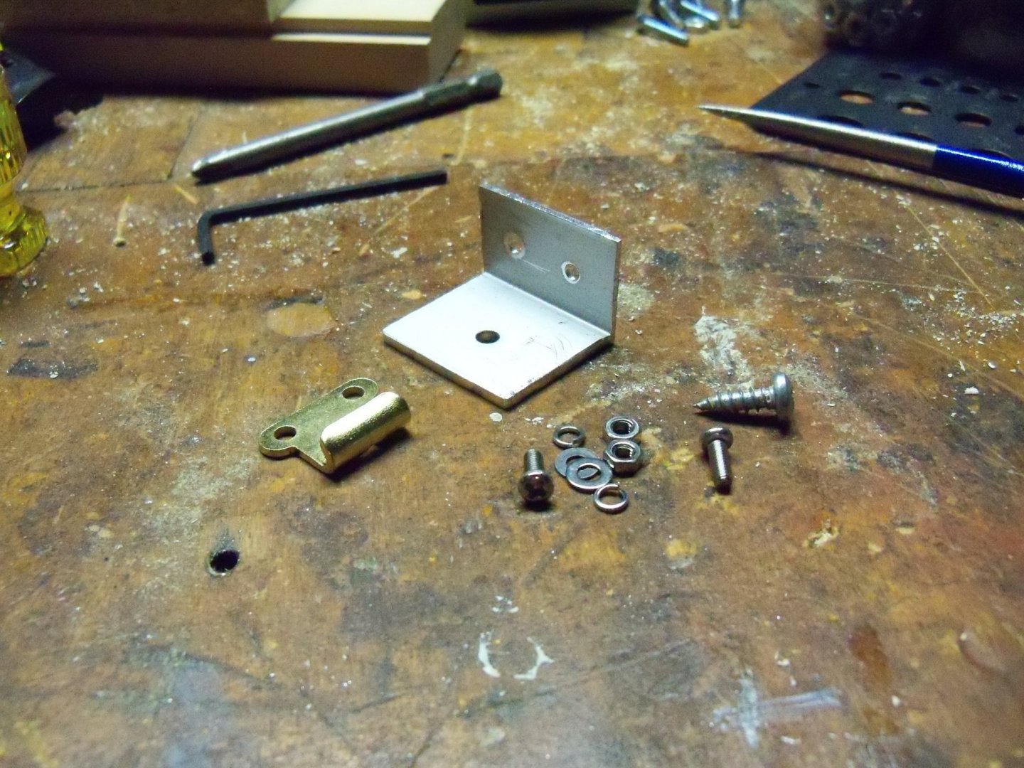
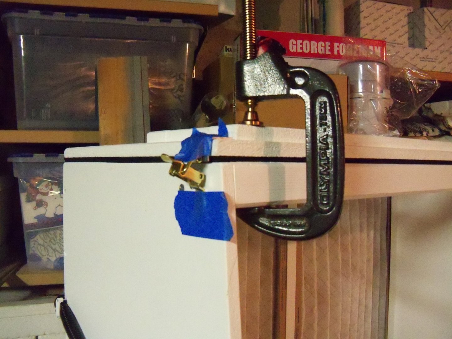
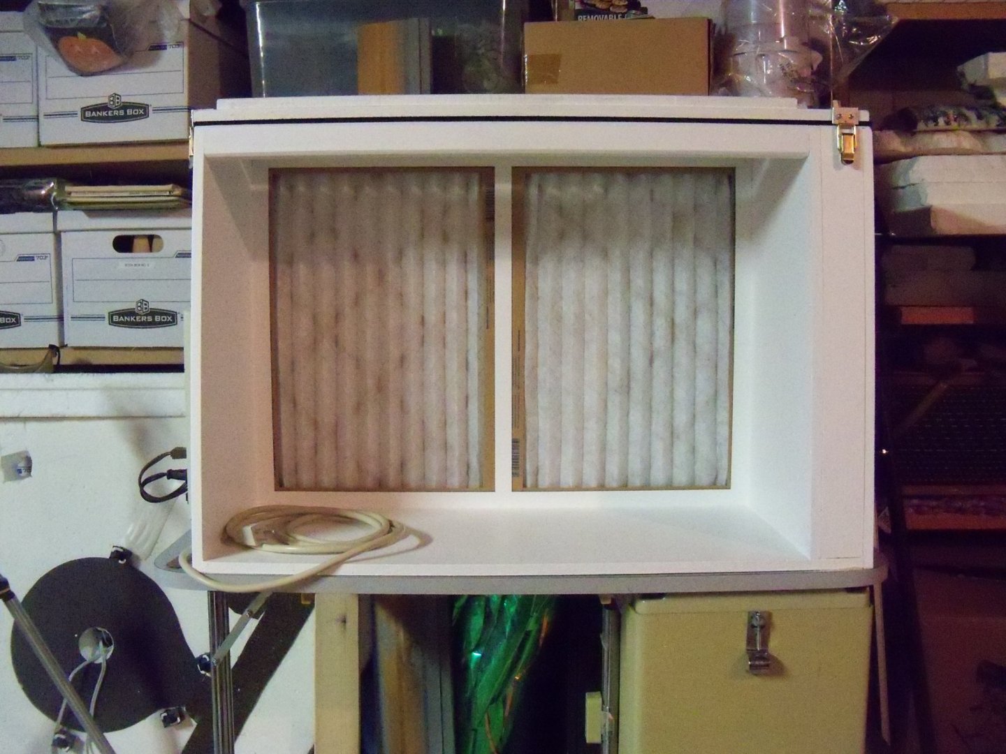
I think that I have come up with a solution now on how to install the draw catches. Since the particle board is so prone to splitting, I will need to reinforce the edge of the top panel to mount the hook portion of the catch. A search ensued for some metal angle to use as a mounting plate. I found a suitable piece of aluminum in my scrap pile that would need quite a bit of trimming. However, since the admiral just bought this new coping saw with a special hack saw blade for me that I was anxious to try out anyway, I decided to use it. Here is the section of aluminum angle that the component was cut from. The first step was to cut a 1 ¼” long section off of the angle. As there was only one inch of clearance for the top of the plate on the left end, this latch was done first to test out my solution. The two irregular edges were then cut off to give the angle two flat surfaces. Once the angle was cut and filed smooth I needed to drill two holes in the vertical legs to match the holes in the hook piece for some small bolts. (I don’t have any tools to tap holes in metal so I had to use the bolts instead.) Then one larger hole in the horizontal leg was drilled for a heavy ½“ long screw. Here is the angle with the needed bolts, flat washers, lock washers and nuts along with the screw for the top and the hook. Once the hook component was assembled it had the nuts and bolts projecting from the backside. So now they needed some clearance holes bored into the edge of the top panel. Once the clearance holes were bored, the component was held in position and I drilled through the hole in the top of the angle into the particle board. The heavy screw was then driven in to complete mounting the upper component of the draw catch. Now all that remained was to install the lower component of the catch. As I mentioned earlier, the foam weather-strip has to be compressed to half its thickness so the top panel will seal it evenly. So, before I could locate the screw holes for this part I used a C-clamp to pull it down. Setting the bottom component in the latched position, a piece of tape was stretched over the mounting plate to hold it in place. The catch was taped up out of the way and the locations for those screws were marked. Once the mounting plate was secured, all the tape was removed and the latch was tested to confirm that, it would in fact work as planned. Since my experiment worked out so well, I made a duplicate for the right end. Since I had plenty of clearance on this end I mounted it on the front face of the booth. So here is the booth as it stands now.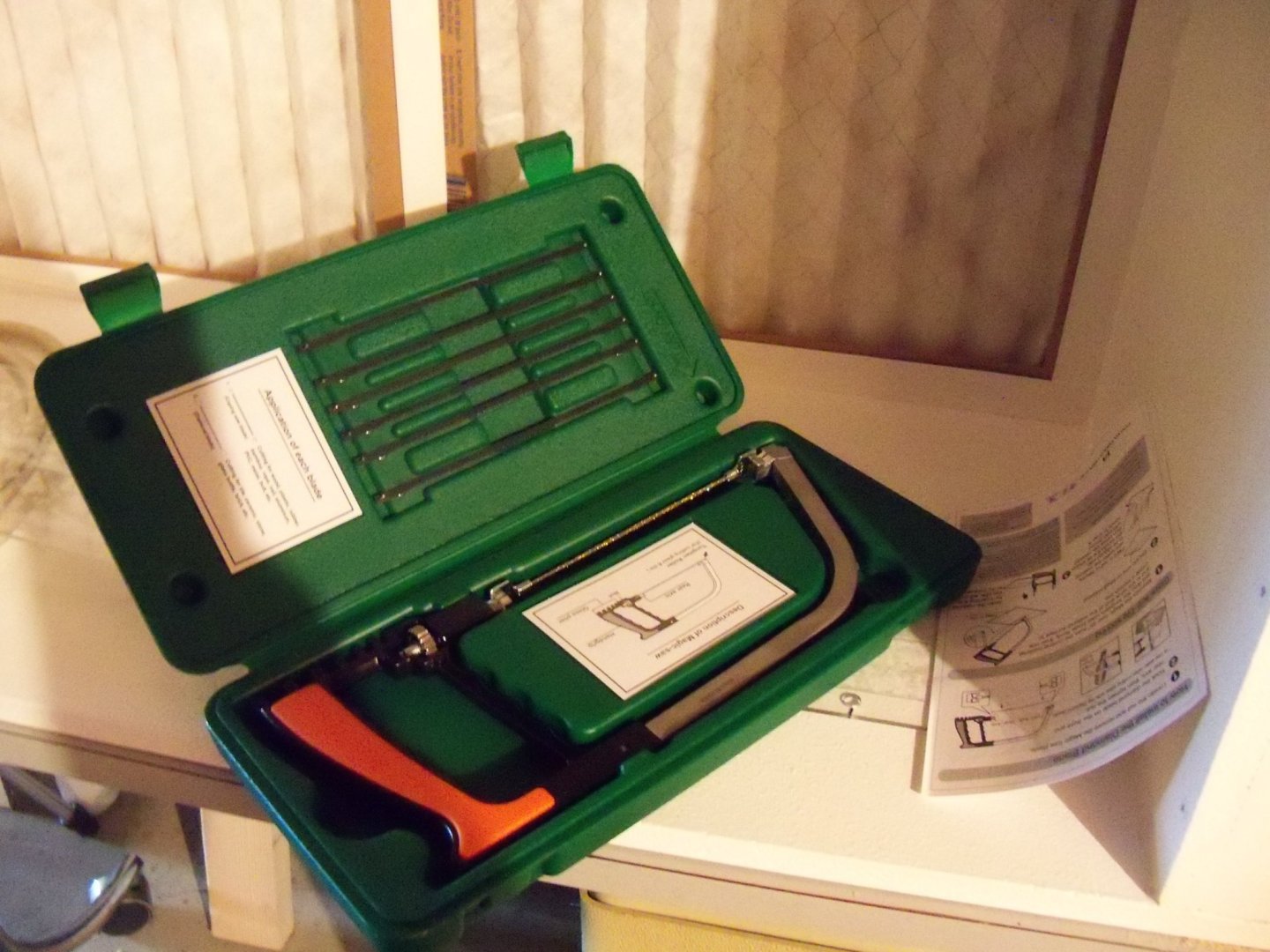


-
Homemade Spray Booth
BETAQDAVE replied to BETAQDAVE's topic in Modeling tools and Workshop Equipment
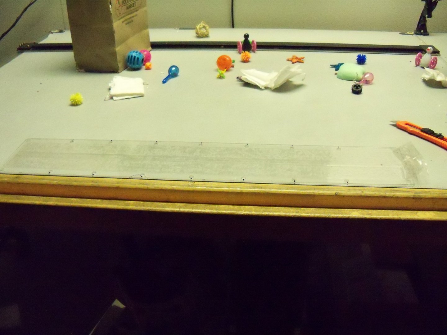
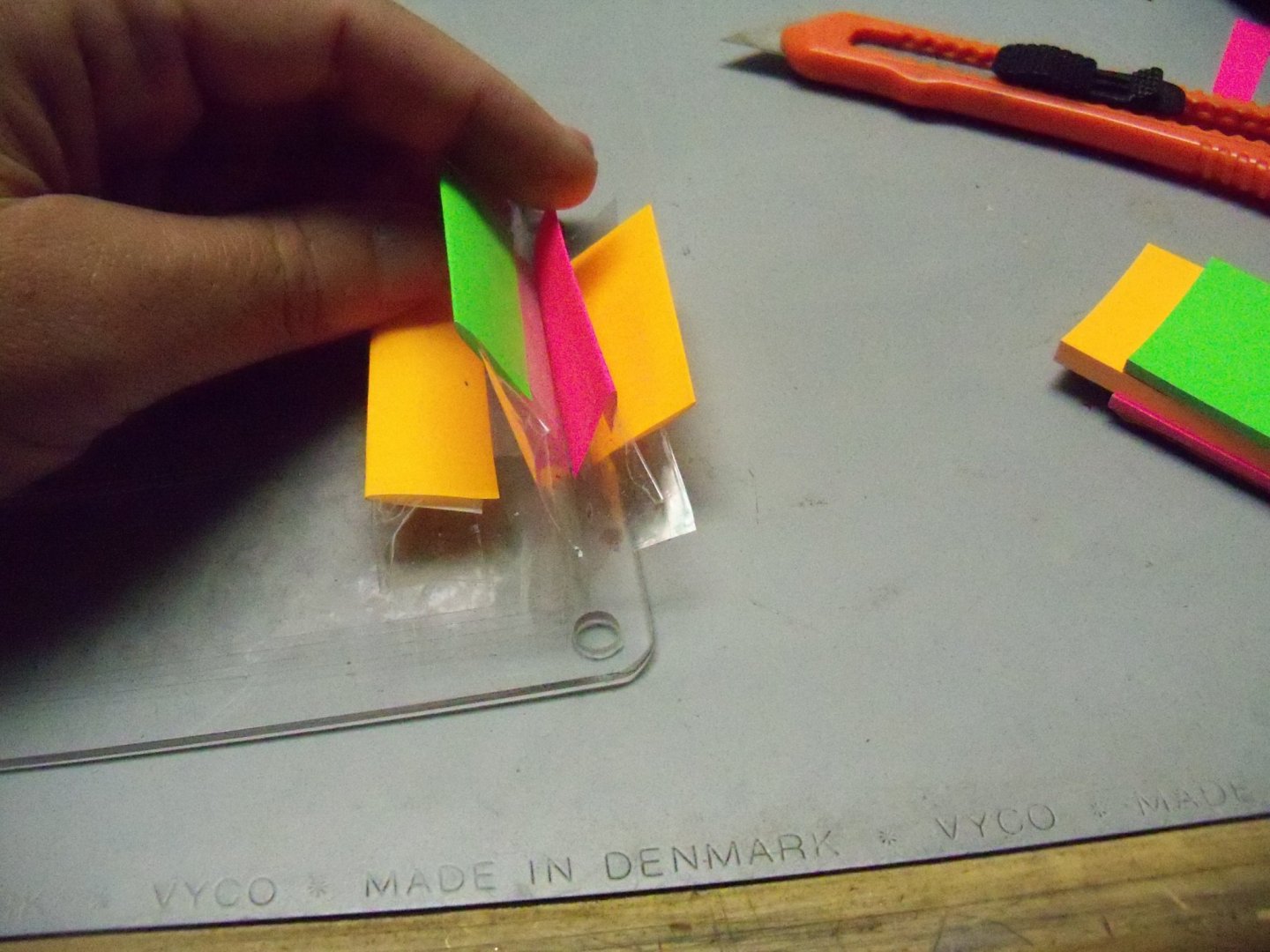
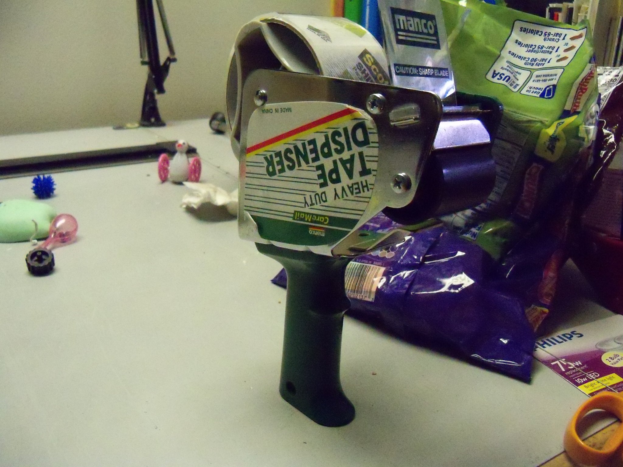
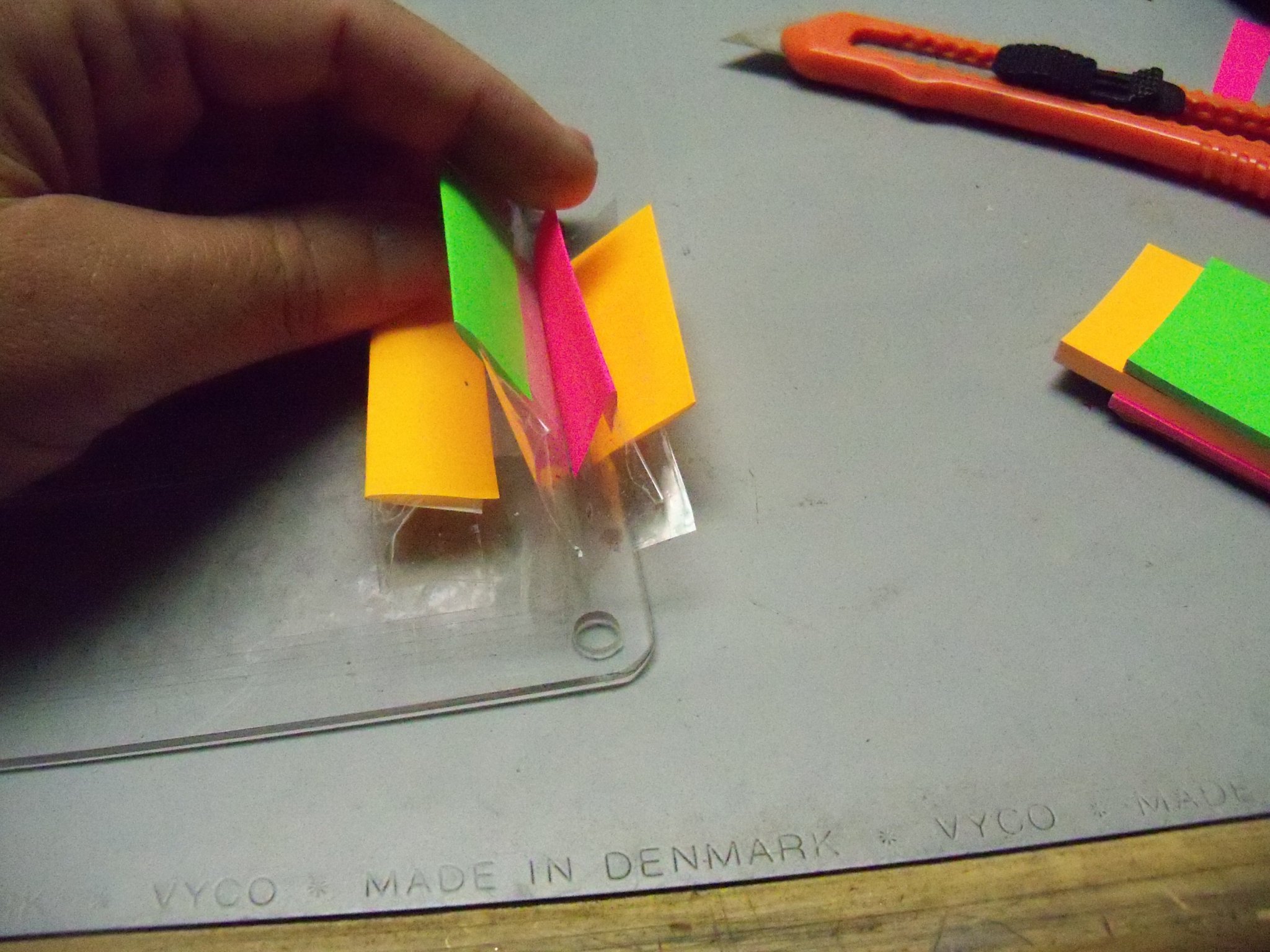
I have a pair of draw catches to install that will pull the top panel down to compress the foam weather-strip and seal the plenum. Unfortunately installing anything with screws into the edge of particle board simply splits it when pressure is applied (I tried that already), so I’ll need to come up with another method of attaching the catches. Today I took the Plexiglas window upstairs to my desk/bird playground to install the tear-off tapes. I cleared off a space to lay the window down flat and since you need both hands to apply the tape I used a piece of double sided tape under each end to keep it from shifting around. Because my window is wider than the tape, I had to use two pieces of tape overlapping each other roughly one inch down the center. While trying to do this operation, I have one suggestion on how not to do this. If your tape is on one of these useless dispensers, get rid of it and just use the tape directly from the roll. It may work on taping packages, but it just got in the way here. I stretched out the first piece of tape aligning it by eye just inside the holes on the edge. Securing the left end of the tape an inch or so beyond the end of the window, I stretched the tape while still on the roll about an inch or so beyond the other end being careful not to touch it down on the window yet. With my left hand I smoothed the tape down onto the window from left to right trying to eliminate any air bubbles as I went. (Not as easy as you think!) Once I had the whole length pressed down beyond the right end, the tape was folded back on itself forming about a one inch tab at the end. I repeated the steps above with the overlapping piece of tape, but the end of this tab was wrapped around the previous tab at the end. This will allow me to pull just one tab to remove both pieces at the same time. I placed three more layers similarly over the first one and trimmed the ends of the tape off on the left with a box cutter. To make it easier to separate the different pull tabs I decided to cut some different colored pieces of post it notes and tape it to the various tabs. Oh, and one more suggestion. Once you have removed the window from the booth, make sure that you are putting the tape on the correct face of the Plexiglas or your screw holes will not line up properly when you reattach it to the booth. (Don't ask how I know this!)