HOLIDAY DONATION DRIVE - SUPPORT MSW - DO YOUR PART TO KEEP THIS GREAT FORUM GOING! (78 donations so far out of 49,000 members - C'mon guys!)
×


yvesvidal
-
Posts
3,607 -
Joined
-
Last visited
Content Type
Profiles
Forums
Gallery
Events
Everything posted by yvesvidal
-
 Kevin, Your yawl looks gorgeous. The blue is surprising on such boat, but so beautiful on your model. Dorade is definitely one of my favorite boats and it has such pedigree. Yves
 -
These baskets are superb. Now, you must build some herrings..... 😉 Yves
- 195 replies
-
- 7
-

-
- lady eleanor
- vanguard models
- (and 1 more)
-
Very cool piece that you built: Le hangar des hydravions. Yves
- 136 replies
-
- 3
-
-
- strasbourg
- finished
- (and 2 more)
-
Porsche 934 by kpnuts - FINISHED - Tamiya - 1/12 - PLASTIC
yvesvidal replied to kpnuts's topic in Non-ship/categorised builds
It is such a detailed model that your idea to present it partially disassembled, is excellent. Yves -
Yes, what a monster. I guess, the intent was to send "candies" all the way to Britain. Yves
-
I meant to say that they used metal parts in the original kit (instead of plastic parts) as a way to charge more money. I am glad that they are replacing the defective parts for free. This is good service. Yves
- 64 replies
-
- 5
-
-
- yamato
- deagostini
- (and 2 more)
-
Superb model. There is a lot of beauty in these small crafts, and your model is a masterpiece. Yves
-
Superb parts. How much were these, if it is not indiscreet to ask? Yves
- 136 replies
-
- 3
-
-
- strasbourg
- finished
- (and 2 more)
-
Superb models. Definitely a Professional Production, at this level. Yves
-
You got some very nice pictures and that kit, in your hands, is going to be another masterpiece. Yves
- 136 replies
-
- 4
-
-
- strasbourg
- finished
- (and 2 more)
-
Very nice results. This kit is almost impossible to paint, since everything is molded in one part. You did a great job. Yves
-
I do. However, I have too many things going on right now, to dedicate any time to this kit. I have to finish my submarine first.... Yves
- 224 replies
-
- 10
-
-
The Build Log can be found here: Yves
-
Speechless.... 😲 I agree with both of you: this is a one time build in your lifetime. Yves
-
Porsche 934 by kpnuts - FINISHED - Tamiya - 1/12 - PLASTIC
yvesvidal replied to kpnuts's topic in Non-ship/categorised builds
Fantastic diorama KPNuts. You are aiming for a first prize at the next show and you will get it. Yves -
Grant, excellent description on the wheels assembly. Thank you for summarizing and extracting the quintessential wisdom of Paul's guide. It is indeed a strong departure from the Pocher instructions, and I can still feel the pain of assembling one wheel (I stopped after that). I will definitely use your technique (and Paul's guide) when I return to this kit. Your model looks stupendous. You can be proud of you, and this steering wheel is only asking to be handled. Yves
- 224 replies
-
- 10
-
-
Superb work Kevin and so realistic. Yes, Perseverance is what you need in this hobby.... and you obviously have plenty. Very interesting videos, too. I also like the non-common boats that you are building, as it provides us with a breath of fresh air from the period ships. Yves
- 72 replies
-
- 3
-
-
- fishing boat
- artisanal fishing boat
- (and 1 more)
-
Excellent choice. I will be watching as well. Yves
- 17 replies
-
- 2
-
-
- martha
- chesapeake bay maritime museum
- (and 2 more)
-
James, being a good moderator will start a new Build Log in the corresponding https://modelshipworld.com/forum/130-build-logs-for-ship-model-kits-by-era-launch-date/ section. I will be following as I followed the concept and creation of that kit by Chris Watton. James on the other hand, will be totally unreachable and will feel at times, as if he has joined some monks order...somewhere in medieval Europe. My condolences to his family and close friends.... 🙂 Building that beast will be epic, to say the least. Yves
-
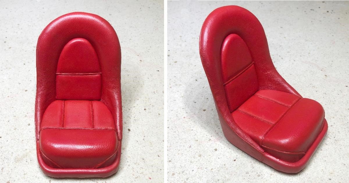
Dave, Model Motorcars is starting to sell Jaguar Type E seats in the scale of 1/8: These may fit your boat better than the modern seat that you have at this moment. You can find information here: https://model-motorcars.myshopify.com/collections/the-jaguar-store Yves
- 51 replies
-
- 5
-
-
- miss unlimited
- dumas
- (and 1 more)
-
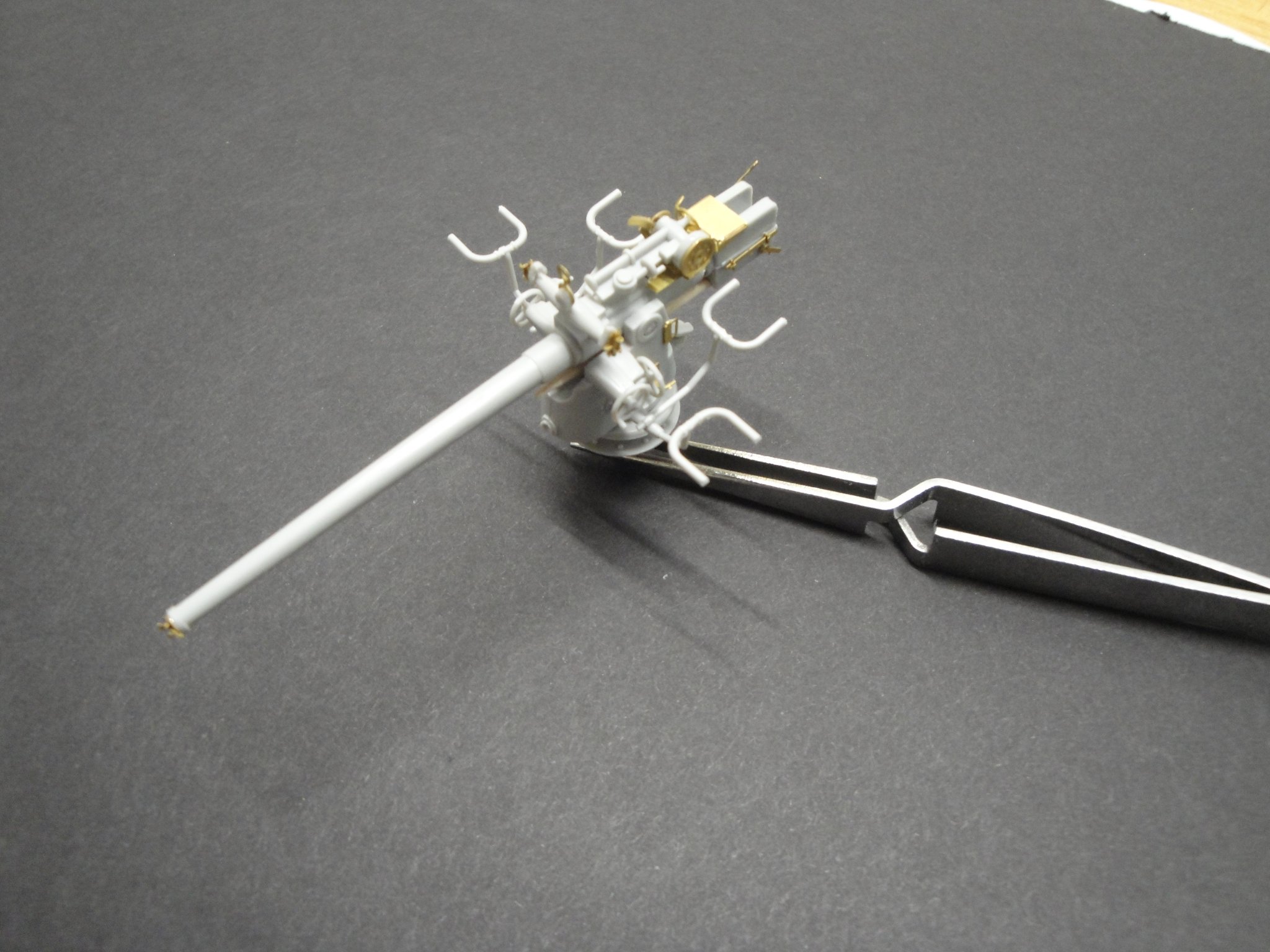
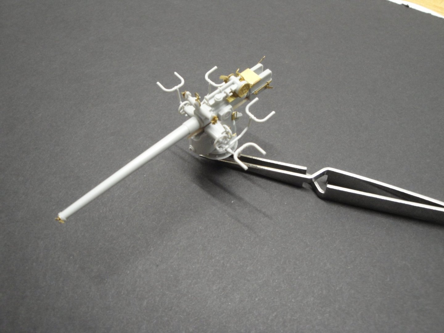
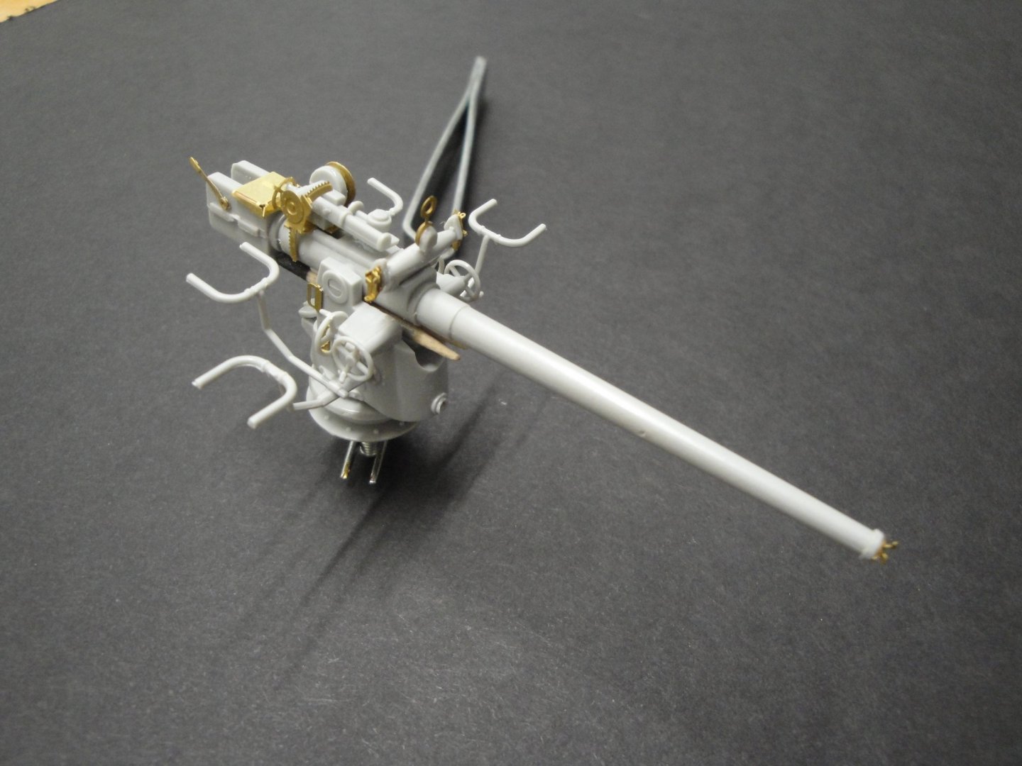
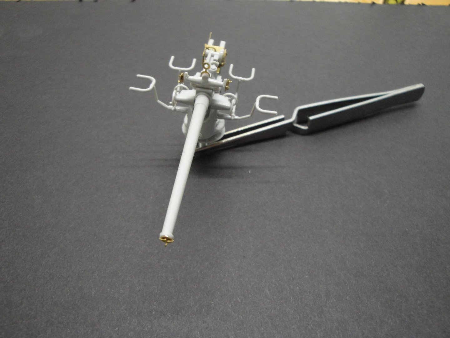
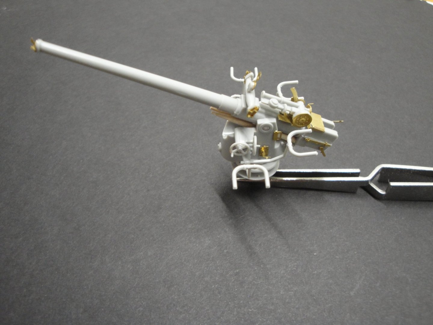
Alright, the main gun assembly is completed. The gun can rotate and swivel up and down: Once again, the PE set from RCSubs saves the day and brings a great level of detailing. Yves
- 760 replies
-
- 16
-