HOLIDAY DONATION DRIVE - SUPPORT MSW - DO YOUR PART TO KEEP THIS GREAT FORUM GOING! (78 donations so far out of 49,000 members - C'mon guys!)
×


yvesvidal
-
Posts
3,607 -
Joined
-
Last visited
Content Type
Profiles
Forums
Gallery
Events
Everything posted by yvesvidal
-
 Beautiful 2nd planking. You are right, that hull can remain as it is without painting. Yves
 -
This is a beautifully planked deck Jolene. Very nice work. Yves
-
Really nice Kevin, very realistic and beautiful. Yves
- 337 replies
-
- 6
-

-
- finished
- mountfleet models
- (and 1 more)
-
Very nice. I love these Circus trains. Yves
-
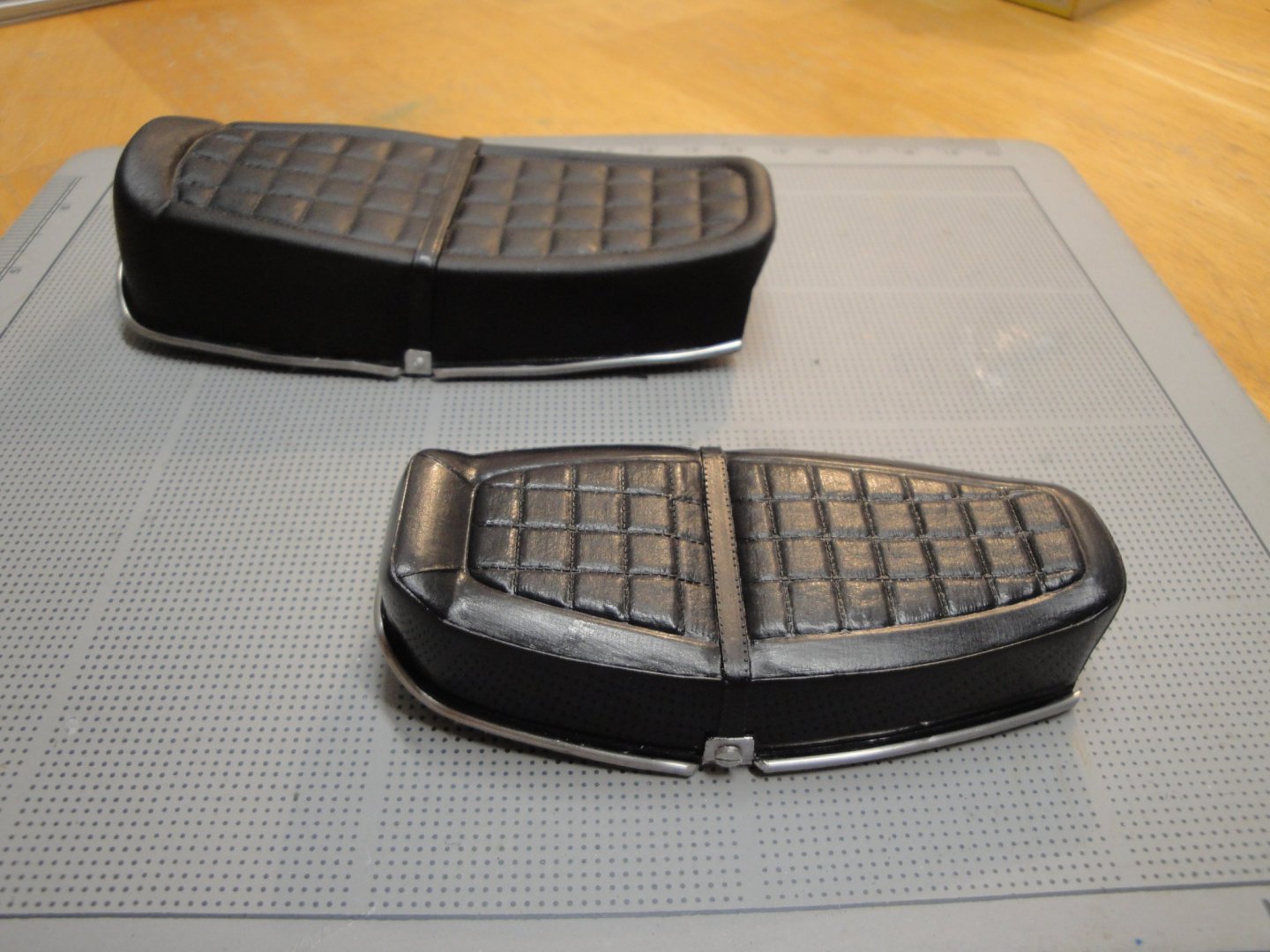
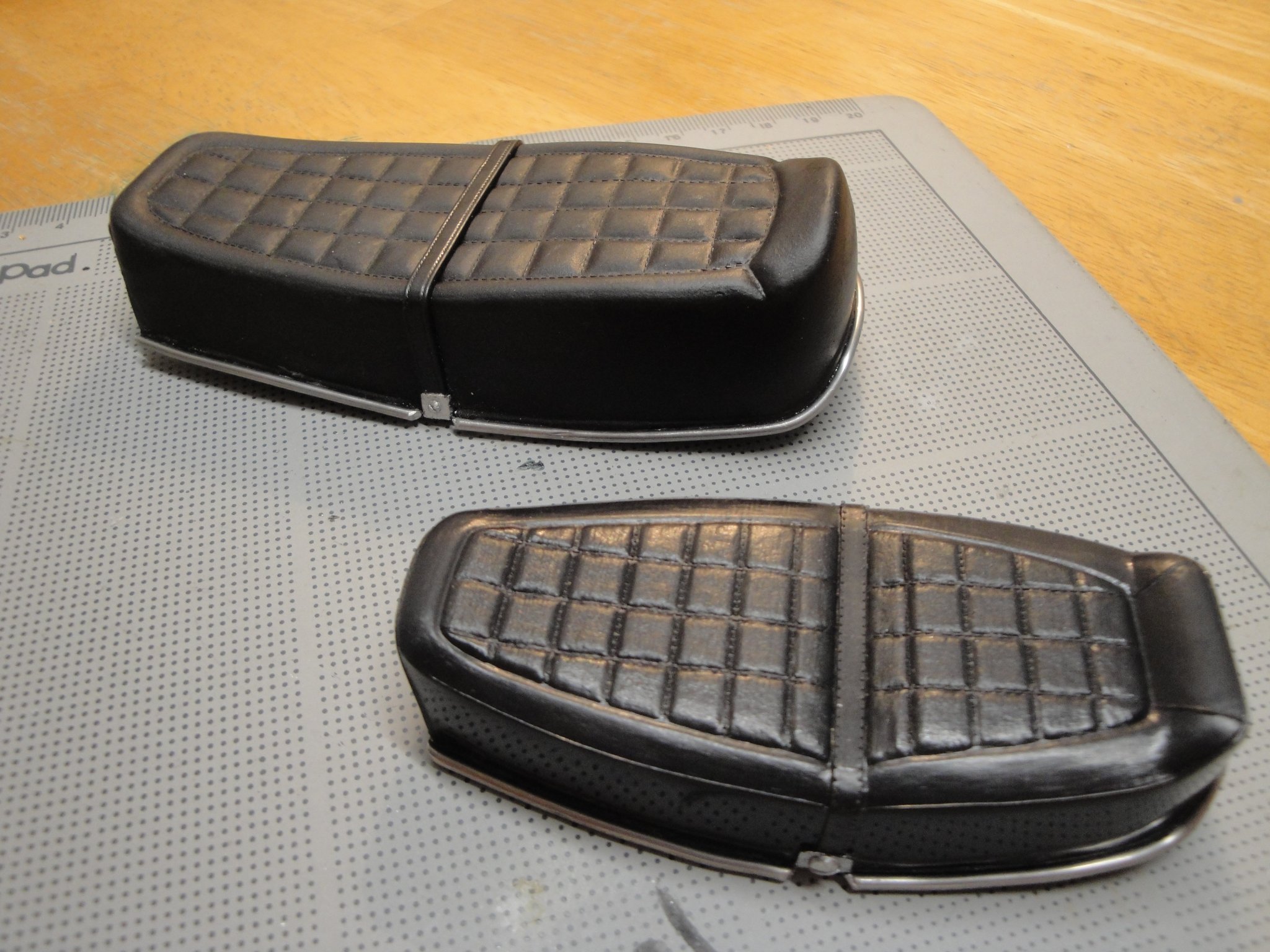
Not much progress on the bikes, but I finished the seats. The seat of the CB750 is quite unique and very comfortable, for an early 70's bike: None of the manufacturers provided the metal decoration that goes all around the vinyl seats. I added these with a thick piece of solder, glued with Cyano-Acrylate. The MPC seat, simpler in its representation, was enhanced with two little screws of 1.8 mm to simulate the anchors of the passenger handle. The Tamiya seat provides a real handle for the passenger, made of some kind of rubbery plastic. The Tamiya seat has a shell underneath and will open on the frame, whereas the MPC is just an hollow shell, glued to the frame. Yves


.thumb.png.fad9a3ec2d94b650b96fcb1bd453787a.png)
-
I fully agree with your assessment of the deck situation. I understand why Chris would provide a "perfect" deck in the kit, as most builders will want their model to look perfect. However, for a fishing boat, the reality is somewhat different. Yves
- 195 replies
-
- 5
-
-
- lady eleanor
- vanguard models
- (and 1 more)
-
That is amazing. Such perfection on a small boat.... Pure jewel. Yves
-
Beautiful. I love the race cars of that era.... No computer or sophisticated technology.... Just pure driving abilities and guts. Yves
-
What? A Ducati which is not red? Sacrilege.... Yves
-
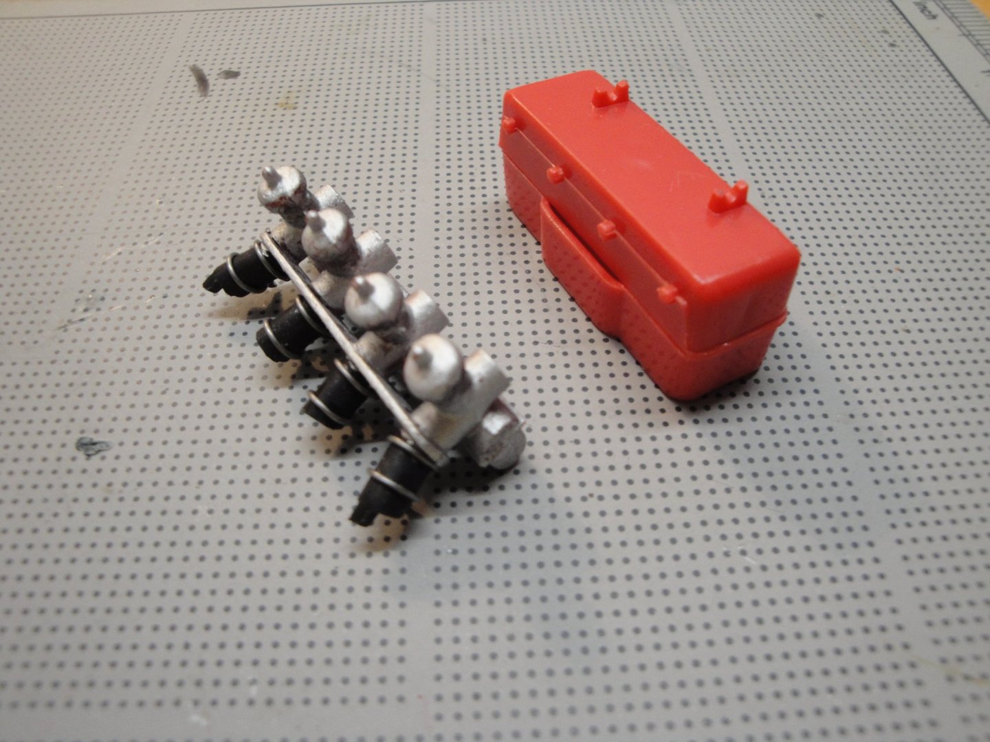
Quick update on the MPC kit. Assembly of the Mikuni carburetors. Quite simplistic on the MPC kit, and I added some collars, using very fine soldering wires: The air box is clearly reminiscent of the K0 model, the early CB750 Four motorcycles. On the K1 and later models, Honda replaced that painted box with a black ribbed and less angular box: K0 airbox on the left and K1-K4 airbox to the right To simplify, MPC does not provide different size rubber hoses, as does Italeri and before them Protar. So, throttle controls and fuel hoses all look the same. Yves
-
You did a great job with this vessel. I built mine 35 years ago and I think it needs a little refresh. The exact helicopter is not yet available in 1/48, but you can find approaching models. Maybe some parts of the existing kits can be used to improve on the Billing Boats helicopter. Yves
- 36 replies
-
- 3
-
-
- calypso
- billing boats
- (and 1 more)
-
Gotha G.lV by ErnieL - Wingnut Wings - 1/32 - PLASTIC
yvesvidal replied to ErnieL's topic in Completed non-ship models
Yes, those guys were true heroes and aces. Yves -
Okay, then you need to provide us with a Build log. This is such a rare and enormous piece that you have to share it with us. Please...please....Please. Yves
-
Gotha G.lV by ErnieL - Wingnut Wings - 1/32 - PLASTIC
yvesvidal replied to ErnieL's topic in Completed non-ship models
You are hard on yourself. This model looks really good and has lots of details. Yves -
I love the Century series of fighters: - F-100 Super Sabre - F-101 Voodoo - F-102 Delta Dagger - F-104 Starfighter - F-105 Thunderchief - F-106 Delta Dart Excellent choice for the F-104, the flying reactor. Yves
-
I cannot believe you have such collection of Wingnut Wings ....and those enormous HPH kits.... Okay, be honest, these are pictures of a shop...right? Yves
-
Bentley 4.5 litre (altered version) by kpnuts 1/12 Airfix
yvesvidal replied to kpnuts's topic in Non-ship/categorised builds
WOW! This is superb. I love the patina and how you resurrected that beautiful model. Yves -
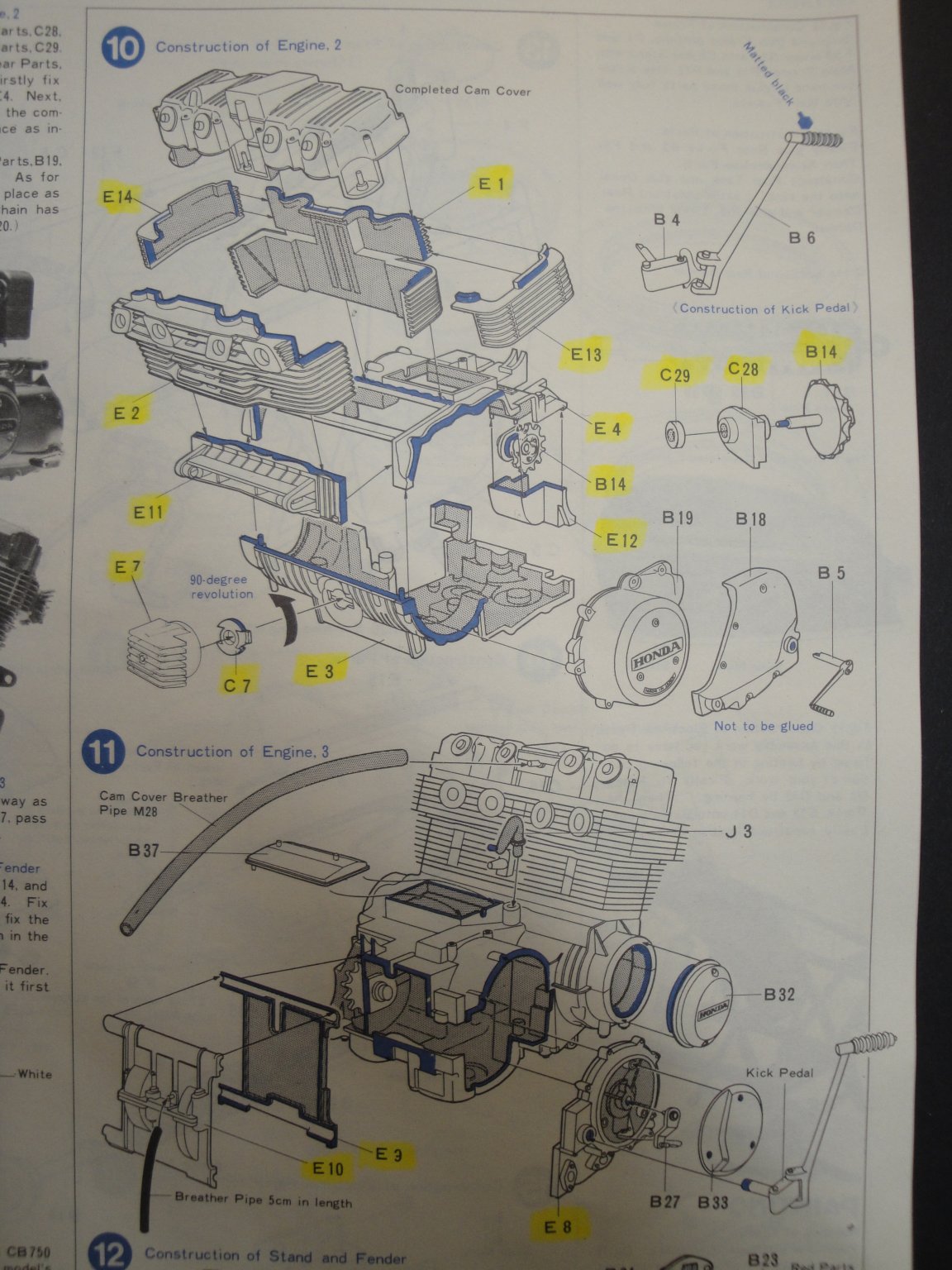
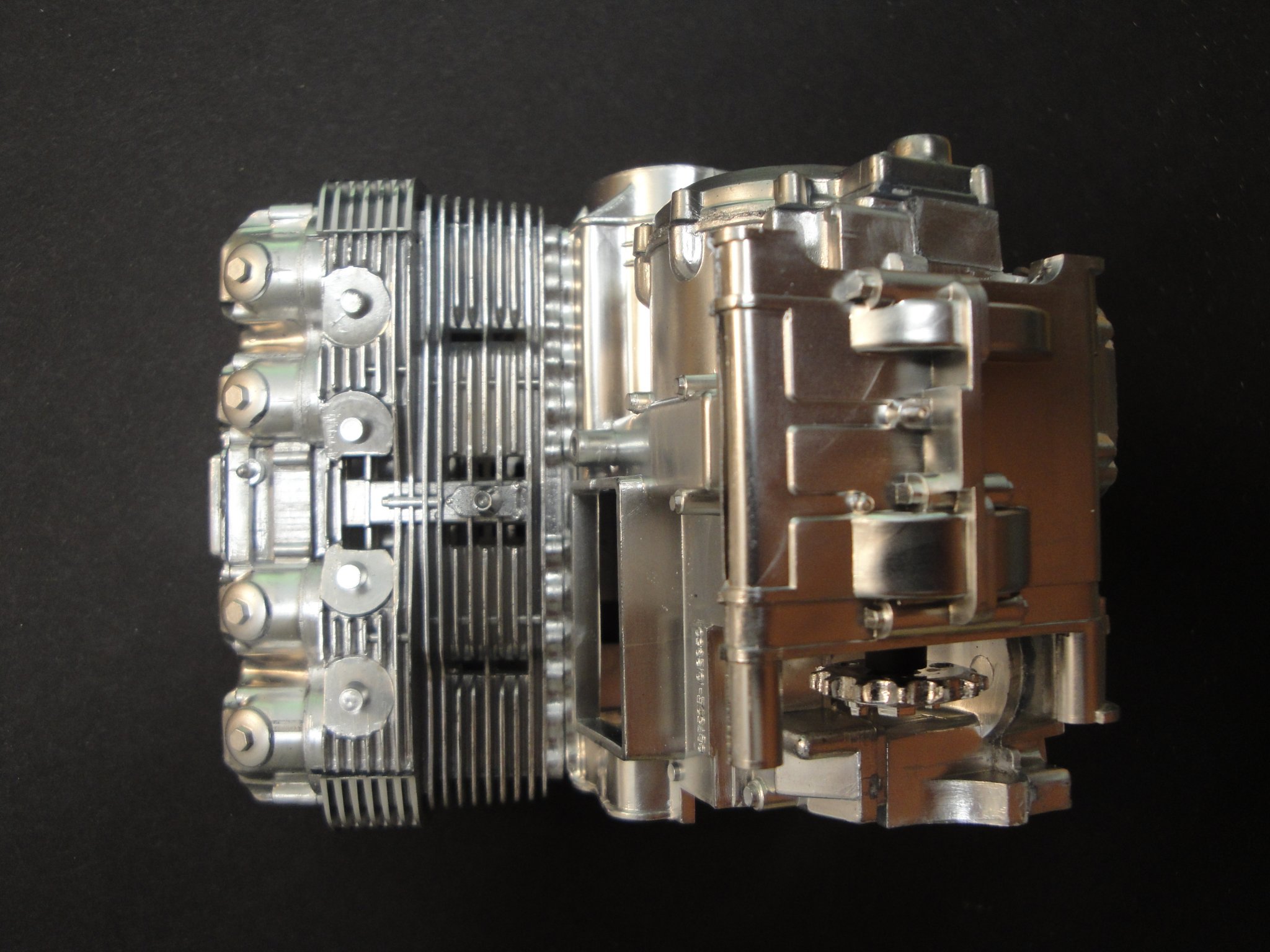
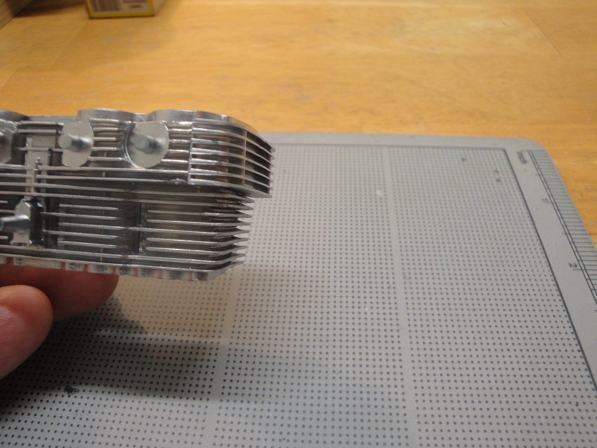
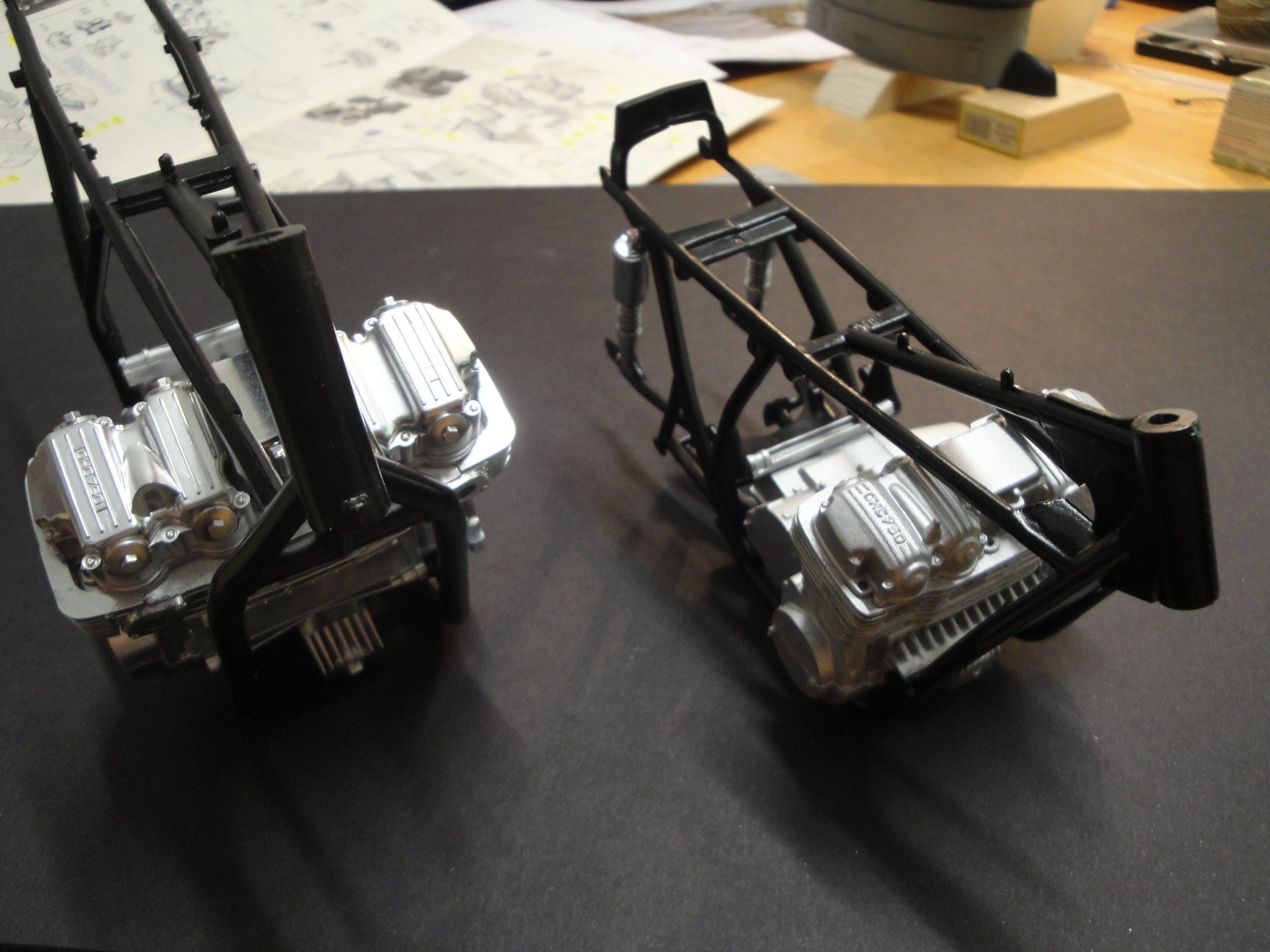
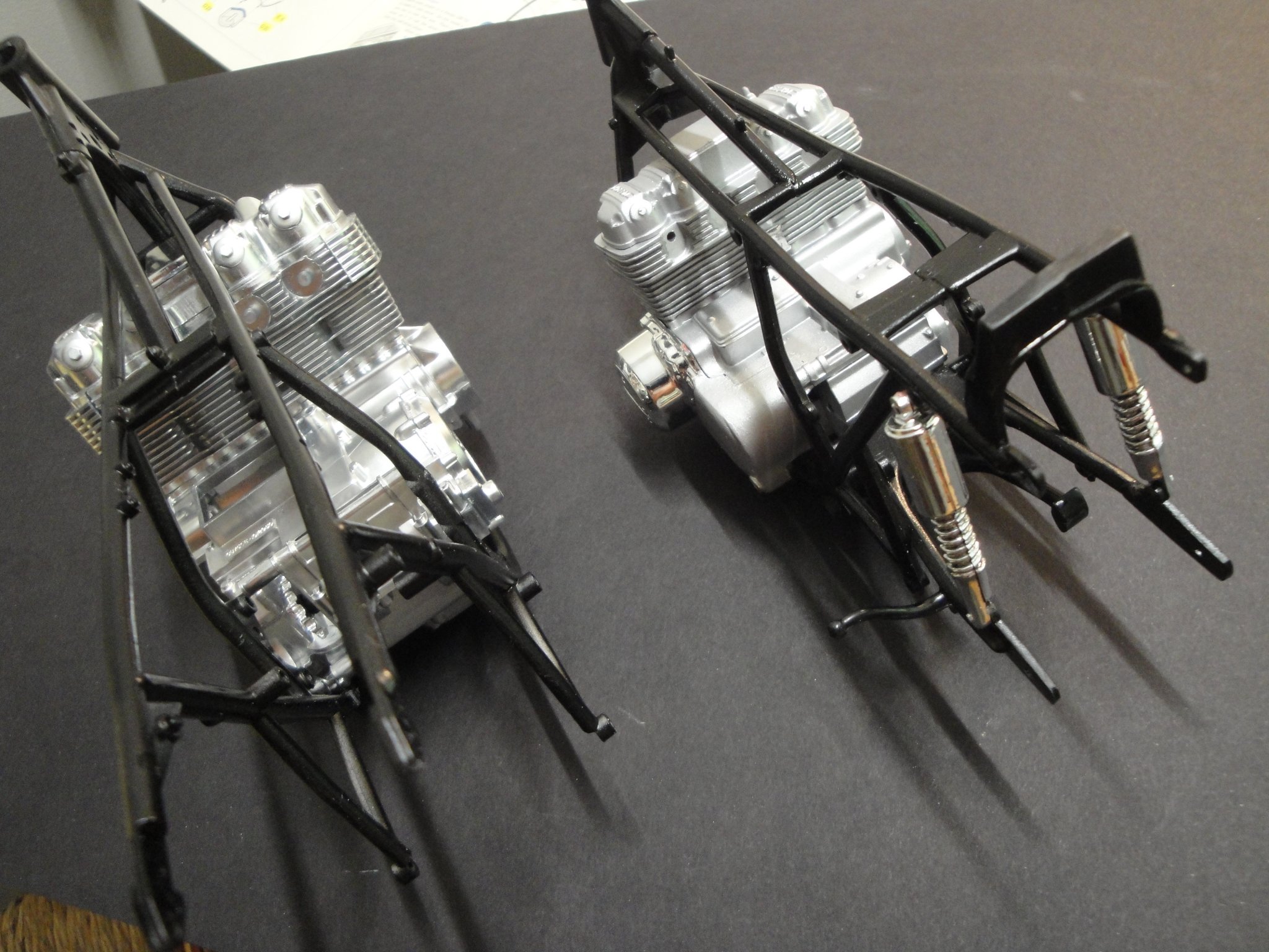
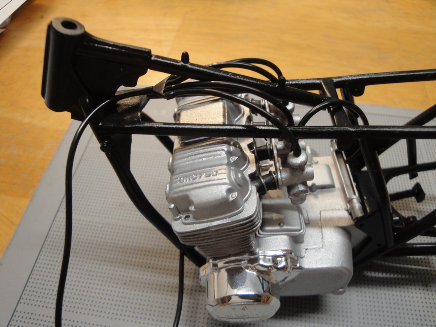
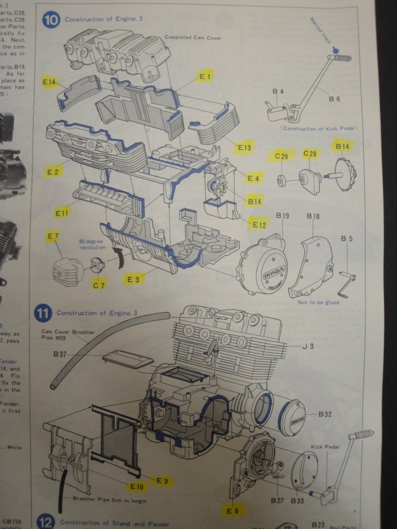
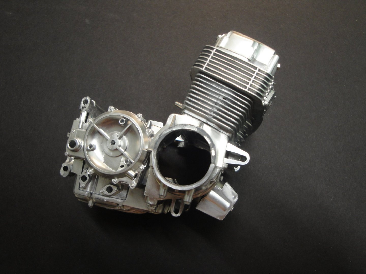
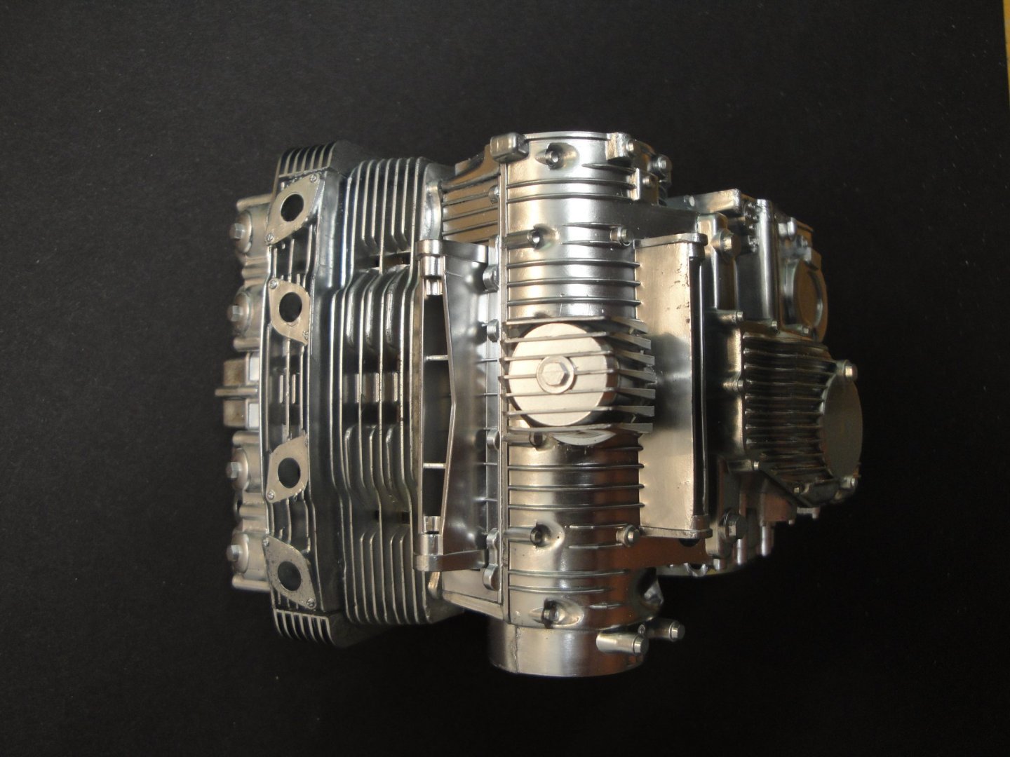
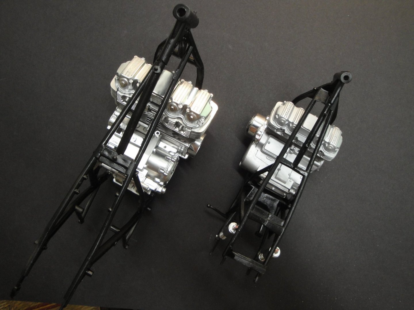
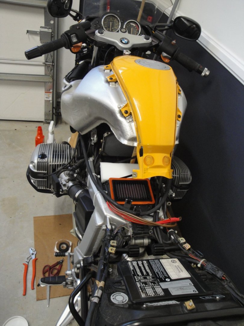
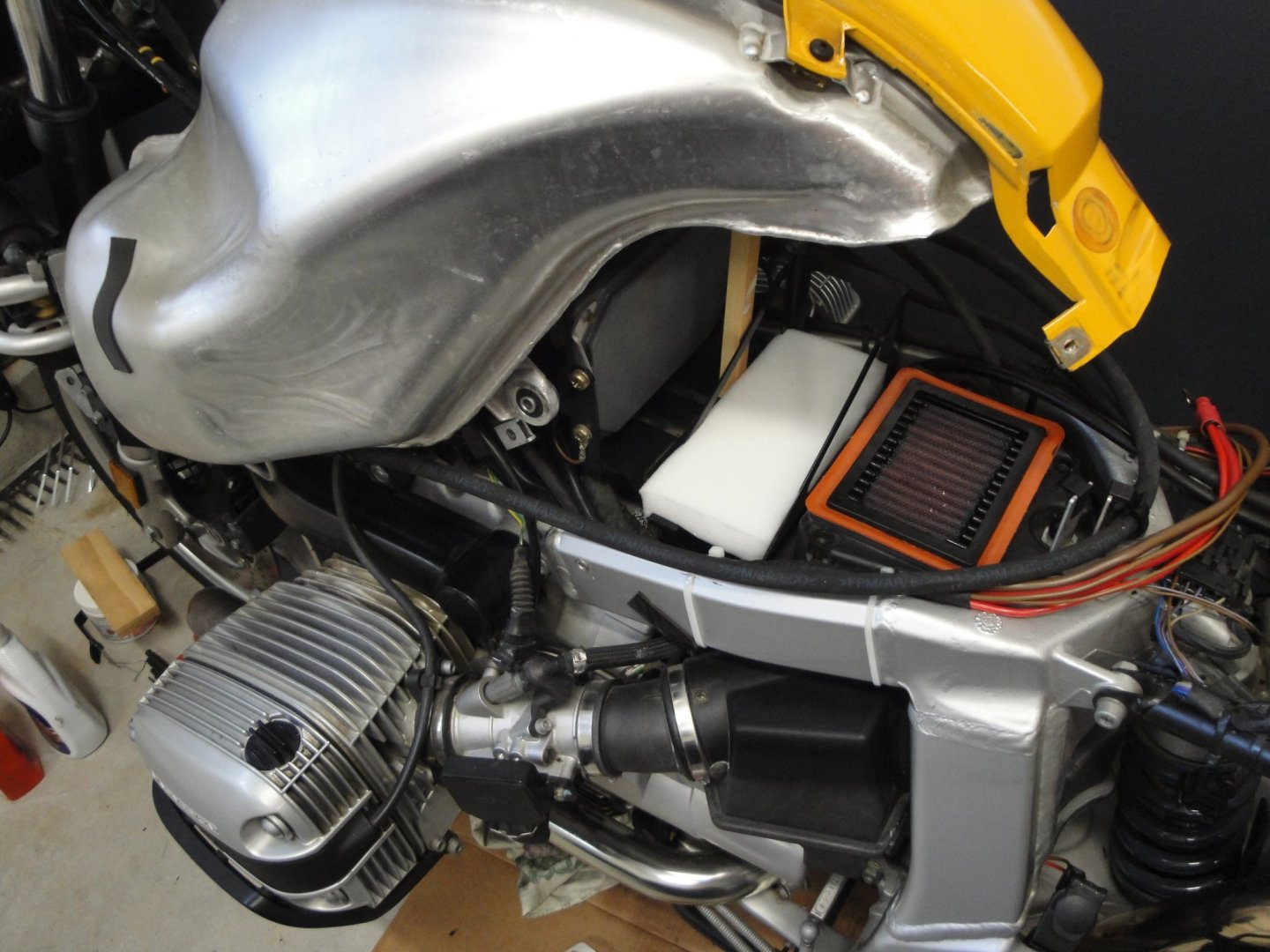
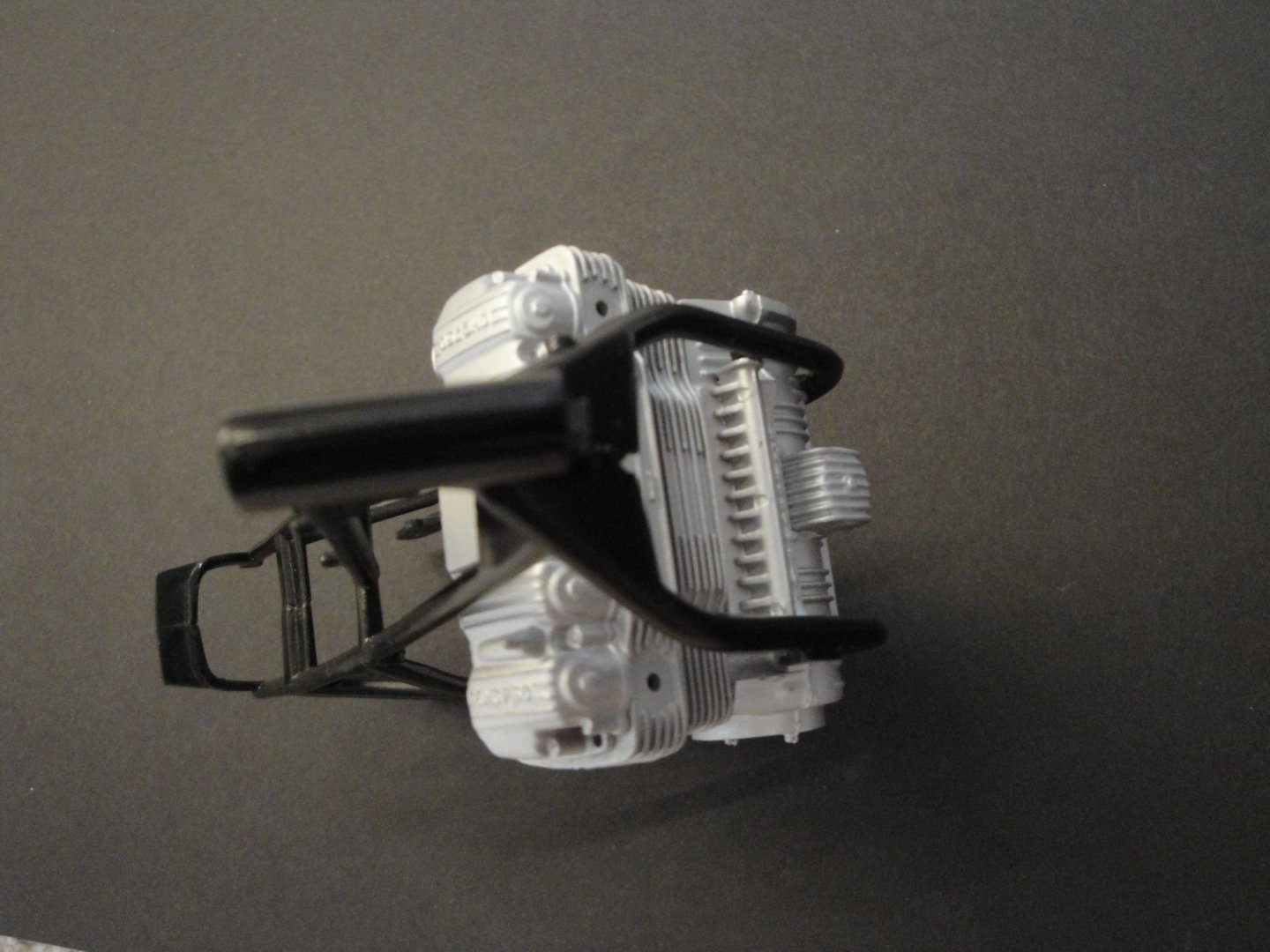
I am now trying to catch up with the Tamiya kit. Assembly of the engine is in order: The Tamiya engine is incredibly realistic and well molded. The color is perfect without being chrome plated. The closer color is the Chrome Silver by Tamiya. Touch-ups are almost invisible. What you see above are just the parts glued. Nothing has been done to the block yet, and no details have been added. The Tamiya engine is not easy to put together and care must be applied to align the fins of the cylinders. You see way too many beautiful assembly of that kit, with mismatched fins: Here, I have tried to align them, by filing the space in between each fin. It is not perfect, but way better than a lot of kits you see on the Internet. Once the cylinder walls have been dirtied a little bit, it should be quite realistic. After insertion (dry run only) of the engine in the frame, we can compare the two kits: The Tamiya kit is 1.5 times bigger than the MPC..... but it seems it is so much more..... To take a break from the models, I am also replacing the battery on my Scale 1:1 BMW R1100S. Not exactly easy to access, but the replacement is done every 4-5 years, so it is not too bad: Battery has been ordered and the K&N filter washed and re-oiled: Yves


-
Finally, a first picture of the Build. Thank you ! Yves
- 195 replies
-
- 5
-
-
- lady eleanor
- vanguard models
- (and 1 more)
-
Amazing build. I really like how you are approaching the building of that hull. Yves
-
Superbe. On se croirait a Carcassonne!!! Yves
-
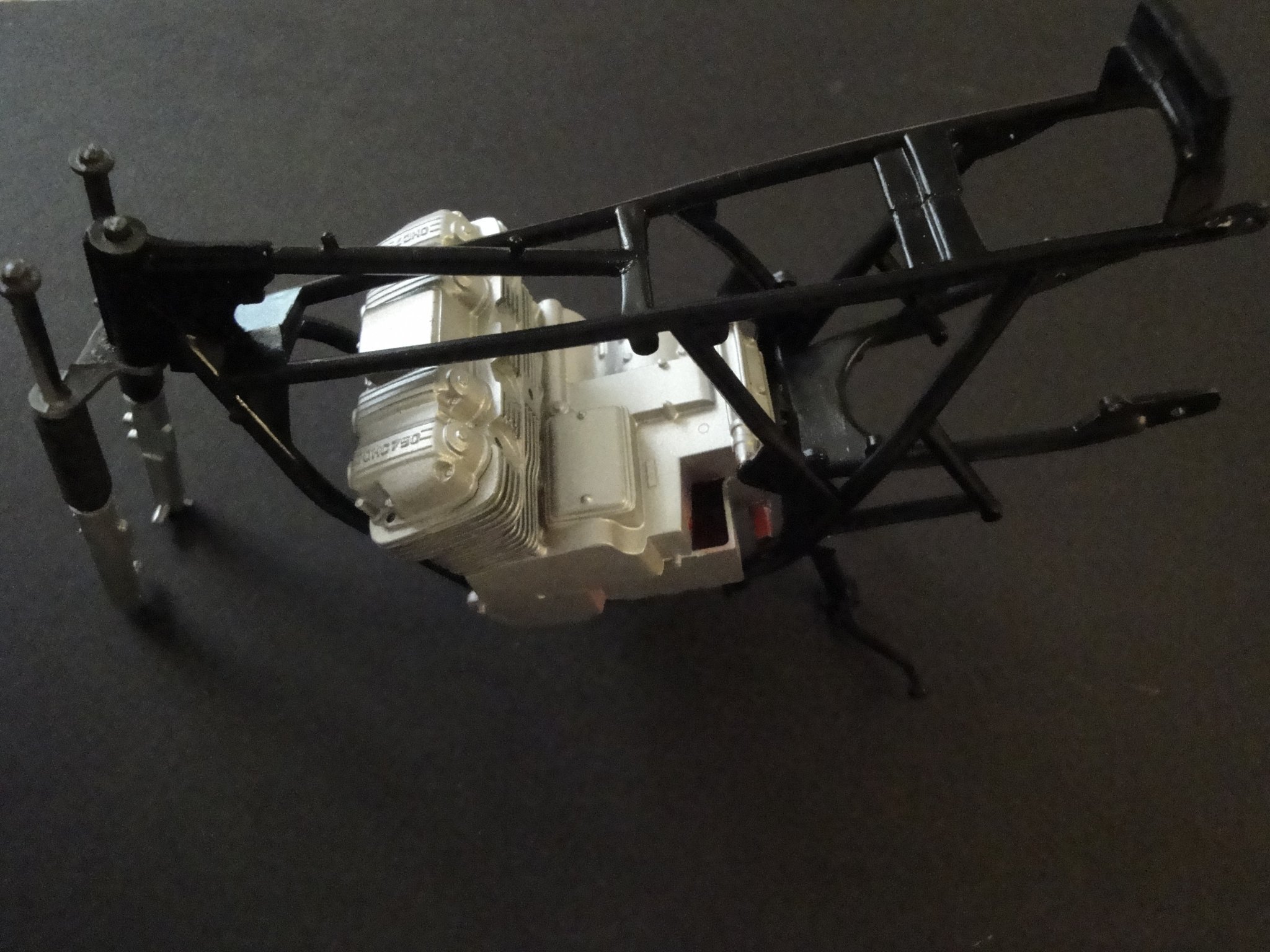
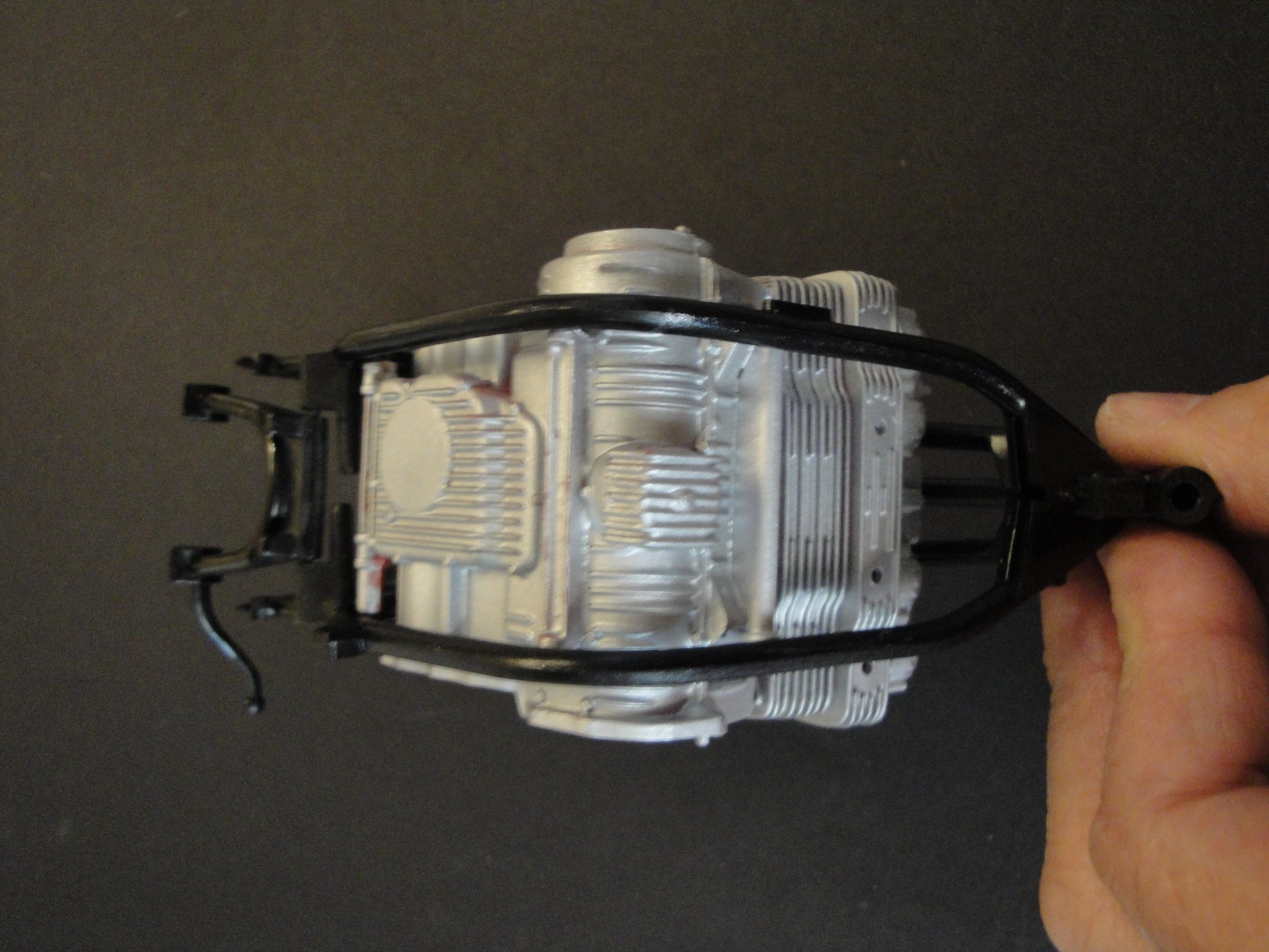
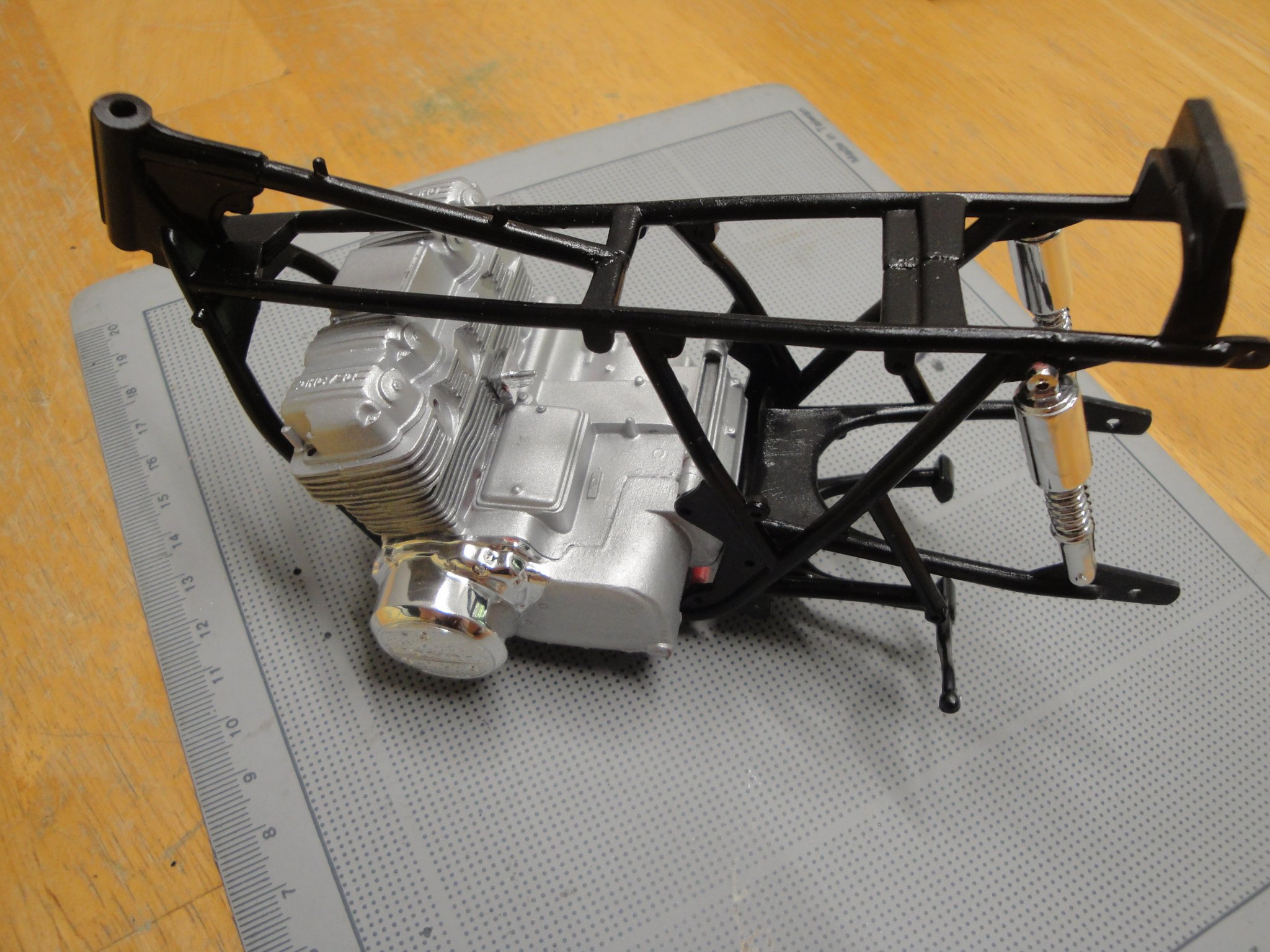
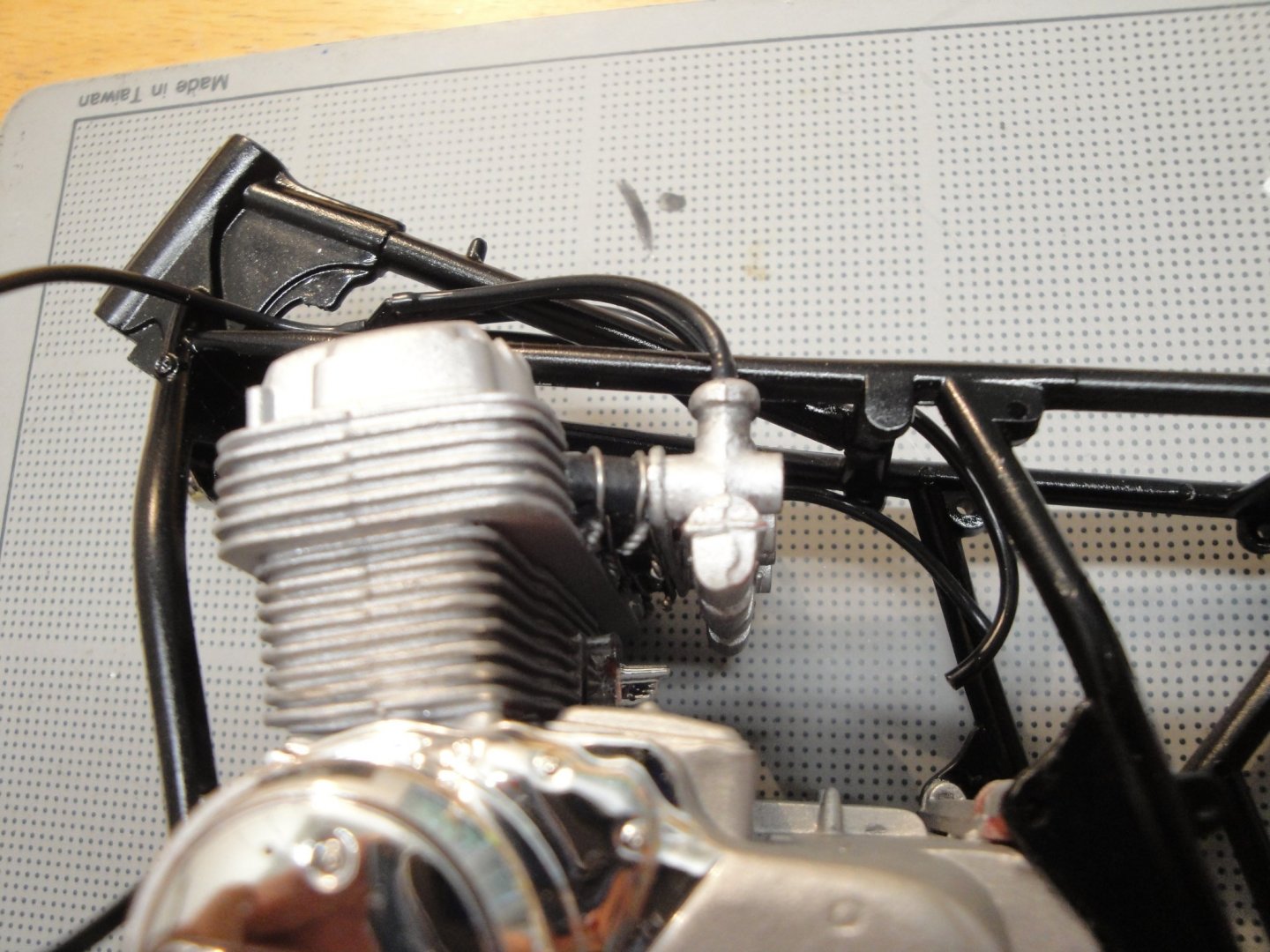
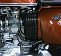
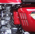
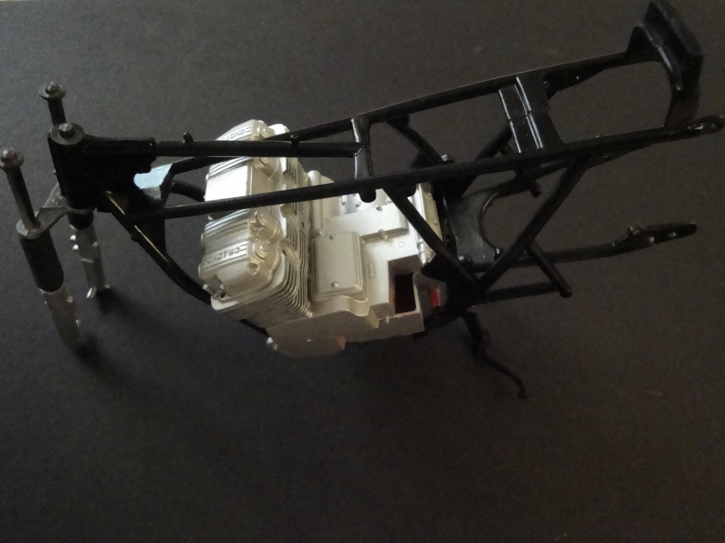
Due to some security firewall issue with this web site, I have lost an entire and comprehensive update on the MPC kit. Therefore, I will only post a few pictures and give some brief explanations (I hate to do things twice). The MPC engine parts were de-chromed in a few minutes, using a warmed ultrasonic cleaner with Super Clean. Parts were assembled, primed and painted Tamiya flat aluminum. Sorry for being so brief, but everything was clearly documented with a galore of pictures in the lost post. The engine was then inserted into the frame and glued in place: And finally, the rear shock were installed, locking the rear wheel holder in place: I have looked at quite a few pictures of HONDA CB750 of the early days. The engine has very few chrome parts and I have only kept that cover, with the original chrome plating. I think that most of the time, it is aluminum highly polished: Now, I need to catch up with the Tamiya kit..... Yves


-
Interesting model. I can see the re-spoken wheels and it does make a difference. Yves


.png.2c6c66294ba1d202f208f50f5740edc3.png)