


SJSoane
-
Posts
1,641 -
Joined
-
Last visited
Content Type
Profiles
Forums
Gallery
Events
Posts posted by SJSoane
-
-
Hi Ed, what a joy to see and learn from this project. As you worked on the rigging, did you see any general organizing principles for rigging that had evolved over time, like what is typically inboard or outboard of each other, why some lines led to tops and others to the shrouds, etc.?
You have done such a great job in the past of explaining the logic of framing as you studied it; I wonder if there are similar lessons after looking at the rigging?
An inspiration!
Mark
-
-
Hi everyone,
I have been working my way through a number of issues fixing the cannon moulds. Following druxey's and Michael's good advice, I have cast plaster sleeves for three of the four masters. I used Hydrostone dental plaster, which worked very differently from plaster of paris. It is a much smoother finish, but it was exceptionally liquid following the recommended mix on the package, of 2:1 plaster to water. I found a manufacturer sheet online which suggested 3:1 plaster to water. I tried this for the second pours and it was better, but still very liquid. The watery mix began to attack the foamcore mould boxes. They are still moist and cold after sitting a day. I will wait until they are bone dry before trying. If I did this again, which I hope I will not have to do, I might try as much as 4:1.
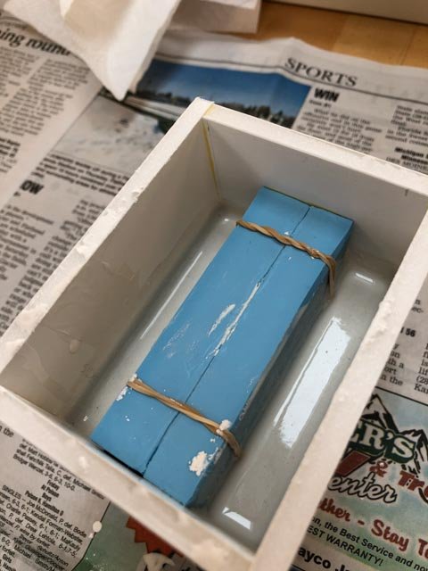
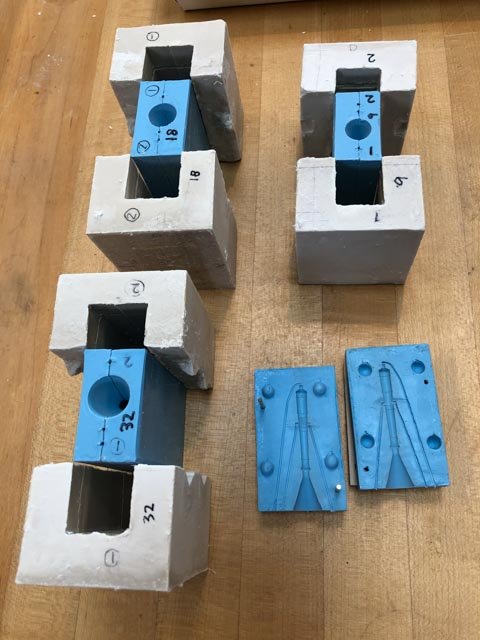
But for the 9" long gun, which was not having registration issues as much as the others, I tried drilling for registration pins through the plywood and rubber sandwich on a drill press in two corners. This seemed to work quite well.
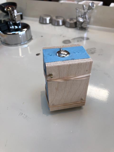
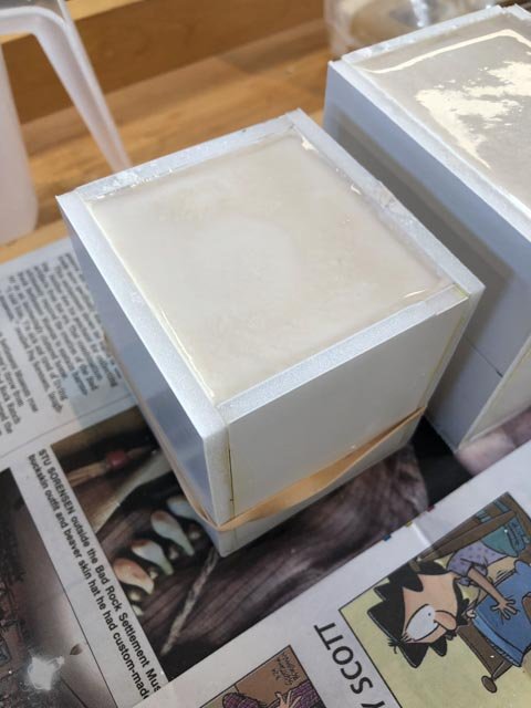
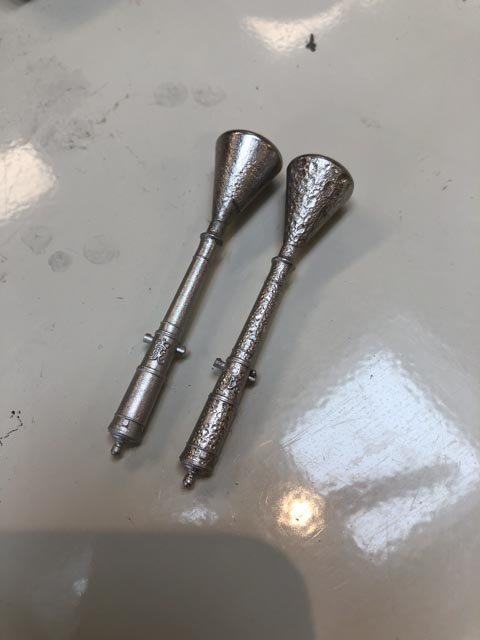
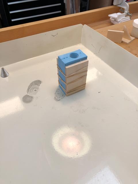
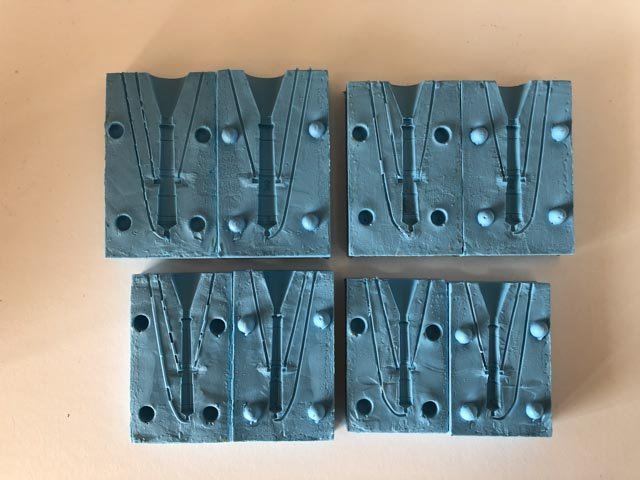
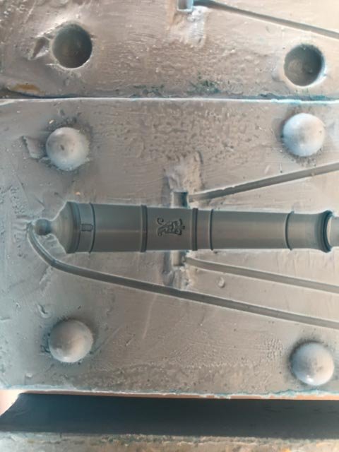
And just for fun, I tried pouring with and without first dusting talcum powder into the mould. You can see the fundamental value of the powder (talcum pour on the left, no talcum on the right.) The one on the right goes back into the melting pot.
Mark
- AON, el cid, GrandpaPhil and 18 others
-
 21
21
-
Thanks, Siggi, the weight of evidence seems to be pointing in the direction of laying them over the button. Since there is no other evidence we have been able to find for the period of ca. 1760 that is contrary to this, I will go with this solution. Plus, it saves making cut splices in 74 ropes!
I am working away on plaster sleeves for my cannon moulds, hope to have something to show in a day or so.
Mark
-
Alan,
I found the Steel tables online: you can see the pages for a 74, and the jib info at:
https://maritime.org/doc/steel/tables/pages/031-ShipOf74Guns.htm
Mark
- druxey, paulsutcliffe, mtaylor and 2 others
-
5
-
-
Last time, I built a foamcore box, lifted the rubber mould half-way up off the base by two cardboard legs, and then poured liquid plaster halfway up. The cardboard legs were then encased in the plaster. I then flipped and poured the other half. It worked great the first time a few years ago, but failed in my recent effort when the plaster set too fast to pour.
So if I can only get wall repair plaster locally, it would work better to build it up like a broken bone cast, with soaked cheese cloth? I assume this is so I don't have to worry about it getting too thick too quickly to pour.
Mark
-
hi everyone,
Alan, thanks for the image. It seems that there are three likely ways in which the breech rope deals with the button on the cascable; the one you have shown, the idea of a cut splice, and the one Siggi showed in the cross section model with it simply lying over the top. Once I start installing the cannon, I think I will make a final decision about which looks the best or makes the most sense.
I can see the value of the plaster jacket now. As the moulds break in, they do not register as precisely as when they were new.
I once used Hydrocal art plaster a few years ago and it worked well for this. But when I tried it again recently, it was very lumpy and it set up before I could pour. So I threw that away.
My choices are more limited in my new little town, primarily plaster of paris for fixing drywall patches.
Is there a reason why I need to order dental plaster for this jacket? Does the hardness matter?
Mark
-
Ah, druxey, I see that now. My failed plaster pointed me in another direction, but I may be back to this if I cannot get the pin idea to work.
Mark
- daHeld73, mtaylor, michael mott and 1 other
-
4
-
-
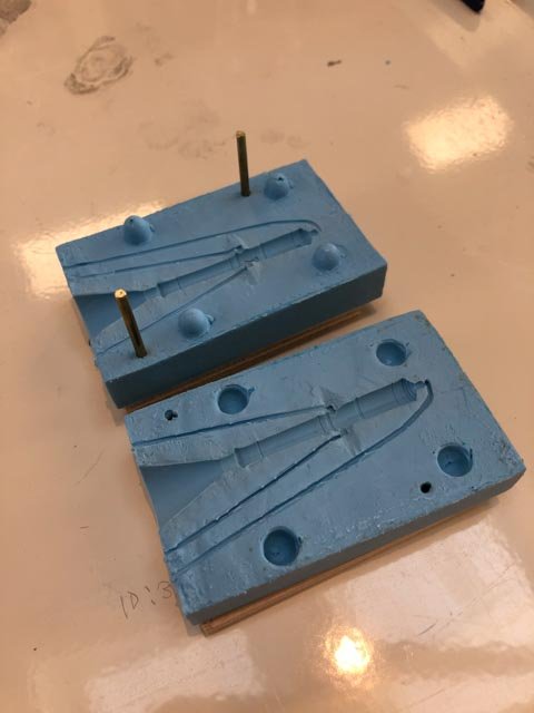
Hi LH, a quick question. Do I assume correctly that the pins should be as close as possible to the cannon shape in the mould? I have a feeling that the rubber stretches a tiny bit across its width, and so it wants to be anchored as close to the cannon shape as possible. Or is it normal practice to keep these pins at the outer edge of the mould box itself? I suppose the only danger is getting too close to the cannon shape, and risking a tear.
Mark
-
-
-
nice drawing!
Mark
- FrankWouts, mtaylor and Canute
-
3
-
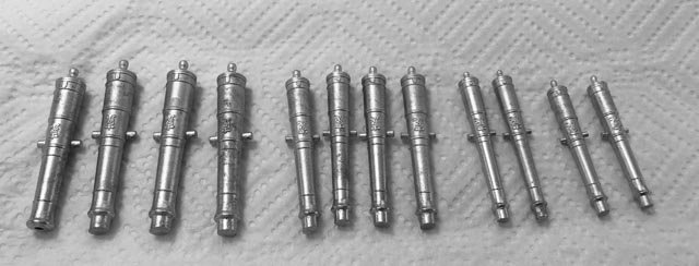
Not much new to report; starting to work my way through 74.
I have noticed, though, that I am sometimes having trouble with the registration of the two halves, leading to mal-formed cannon. The rubber moulds are no longer as sticky as they were when new. I think this allows them to slide around a little relative to each other. I have to be very careful to ensure that the mould sides are aligned when clamping them between the pieces of wood with rubber bands.
We will see if the 32# and the 24# moulds are durable enough to cast 28 good cannon each...
Mark
- michael mott, Jack12477, DORIS and 8 others
-
11
-
-
Thank you, albert, Marc, Mike, Greg and druxey, for your words of support and encouragement. This cannon project seems to have been an exceptionally long time in development this winter, and I haven't even begun mass production. Your continuing support really helped keep me going when the project got a little bogged down at times.
Thanks again to Chuck for providing those exceptional king's cyphers. They look great in the casting, and I concede that it was beyond my ability to create them after numerous failed efforts. I may still try photo-etching when the sun comes back this summer, just to see if it was a problem with using an incandescent bulb instead of the sun...
Greg, I haven't seen the idea of a cutter; intriguing. Do you recall where you saw it? I am reworking the split collar for clamping the barrel in the lathe, because it is still not quite centering the drill. I will show experiments as I work on it.
druxey, I last used Jax's Pewter blacking on earlier experiments, which seemed to work well. But I have noticed that some cannon treated this way a few years ago lost the blacking in a few places like edges on the face of the muzzle. Do you have thoughts about how to clean the barrels for Jax's to work better? And my Jax's is a few years old; do I need to get a fresh supply?
Thanks again, everyone,
Mark
- druxey, paulsutcliffe, daHeld73 and 2 others
-
5
-
I picked up a cold on the plane back from our trip, which slowed me down the last week. But now better!
I initially tried building a Plaster of Paris sleeve around my moulds, to stabilize them and pull the two halves together securely. But I had trouble pulling them tight with tape before pouring the plaster; for some reason, this time, the tape just would not secure tightly to the rubber. And then I used old plaster, which was so lumpy and needed breaking up that it began to harden before I could pour it into the boxes. I had to throw all of that away.
Reading the Micro Mark instructions again (when in doubt, I keep telling myself, read the instructions), it suggested pressing the moulds halves between two pieces of wood. I initially tried that using clamps, but this distorted the mould and I cast an oval section gun.
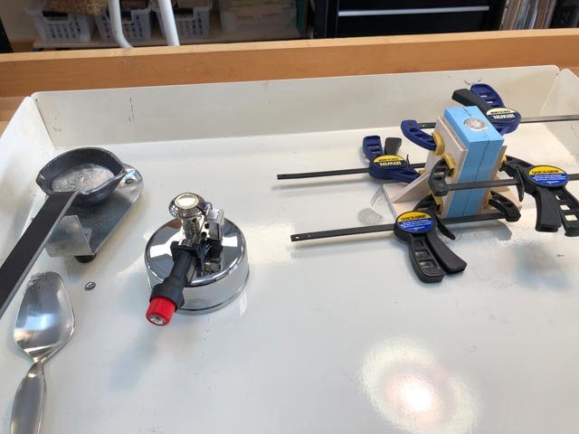
So then I tried holding them together with rubber bands (per the instructions), and this worked well.
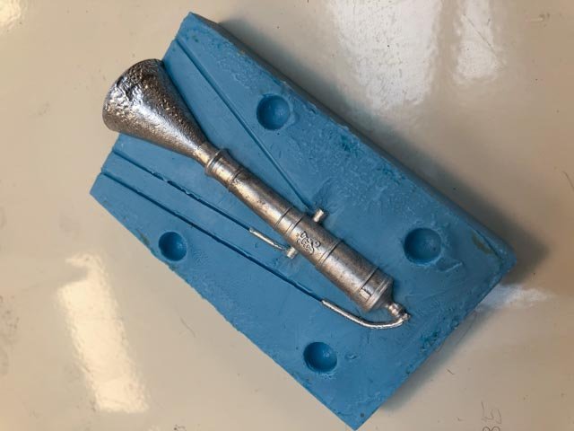
Here is the first cast:
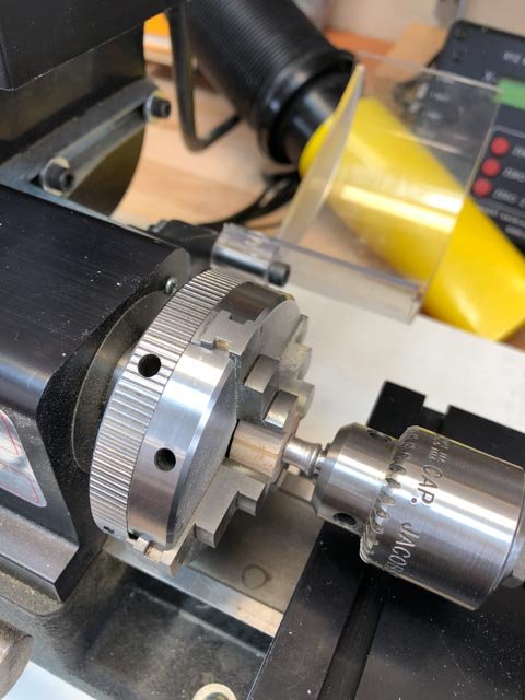
Once I cut off the gun head with a jeweler's saw, I clamped it in the lathe, using a chuck on the protruding end of the muzzle to center it, and then clamping it in a four jaw chuck using a split ring of wood.
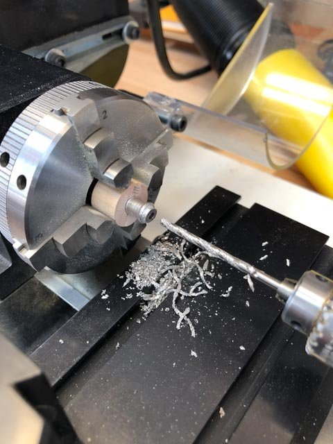
Then I could drill for the bore, and face the end.
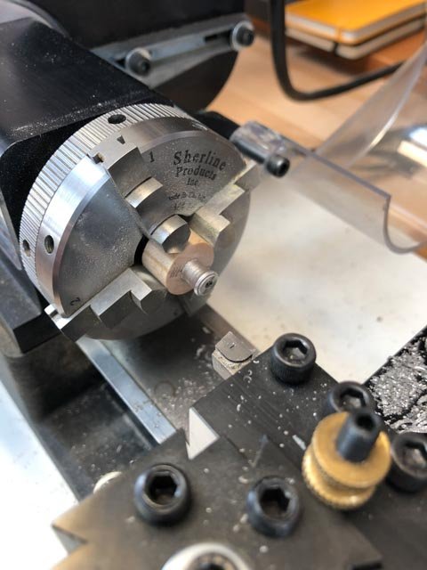
And the result:
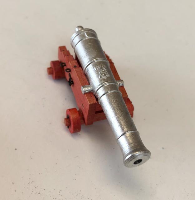
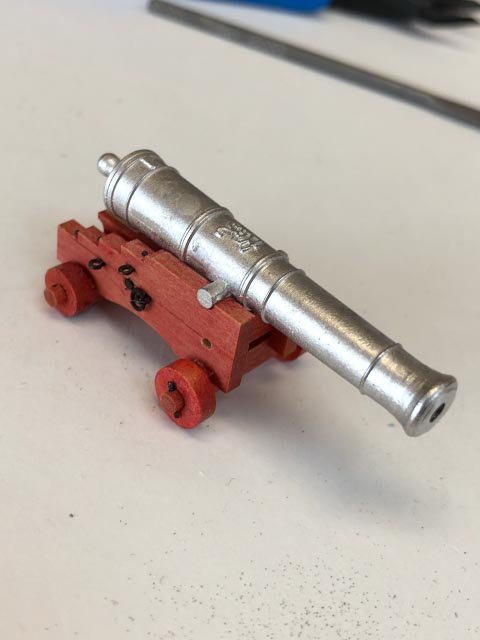
Needs a little filing to clean up the trunnions, but the process seems to work.
Mark
- Amalio, JOUFF, michael mott and 26 others
-
29
-
Siggi,
Fantastic crew figures! Well done!
Mark
- Siggi52, FriedClams and mtaylor
-
3
-
Gaetan,
Beautiful knives! Let us know how they work!
Your photos look like they are taken inside a real ship. Beautiful construction.
What camera lens are you using to keep such great depth of field?
Mark
- mtaylor and FriedClams
-
2
-
Thanks, druxey, it is amazing how many details seem obvious until you start actually working with them.
The rubber pours were successful! No bubbles, good rendition of detail including the king's cypher.
I did have a moment of concern when the two halves intially would not pull apart, but once I peeled off the outer paper boxes, the rubber came away nicely.
Plaster of Paris sleeves next.
Mark
-
Hi druxey,
Retirement seemed like a good idea until I discovered that my brain flew out the window. When I was juggling a dozen things, I could still keep track of details. Now I have only one thing to juggle, the details slide away. Or, maybe it is aging!
So here are some decking questions, while my moulds dry.
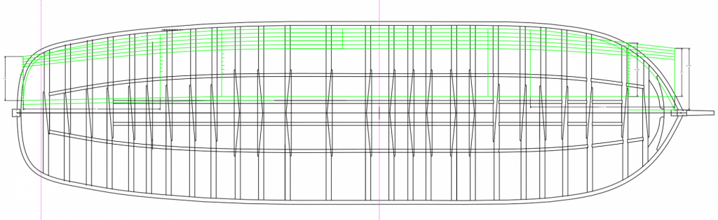
I am laying out the decking for mounting the guns, likely building 5 strakes from the waterway to accommodate the length of the guns.
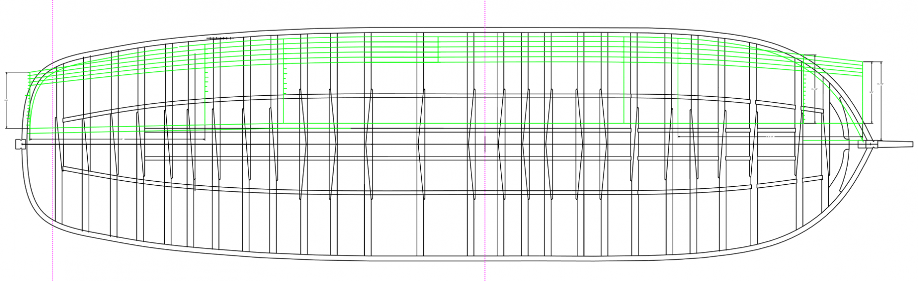
Do I have it right that a 3 or 4 shift planking plan has all of the butts falling on beams, not any ledges? This means that the lengths of the strakes are quite irregular, given the irregular spacing of the gundeck beams (see above).
Is there any particular functional or historic reason to choose 3 or 4 shift planking? Goodwin suggests that weather decks were 4 shift, but I see no other information pertaining to the gundeck.
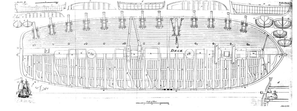
I am assuming that the planks taper at the bow and stern, as Falconer shows. I am also assuming that there is NOT a band of anchor or top and butt planking adjacent to the waterway in this ca. 1760 ship. Goodwin (p. 59) says that this practice came in only at the end of the 18th century.
Mark
- mtaylor, daHeld73 and paulsutcliffe
-
3
-
I poured the second rubber for the first two boxes, all went well. Then I started pouring for the final two boxes, and just as the stream started into the box I realized that I had not coated them with mould release! Retirement seems to have addled my brain. So I mopped it out, and will have to wait until it dries to make sure there is no rubber left from the aborted pour before starting again.
While waiting, I started working on the planking plan for the planks under the guns. I have copied the run of planks from Falconer. Next, working out the plank ends.
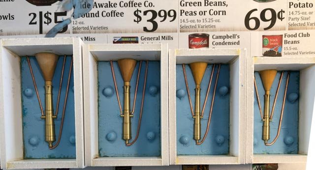
Michael, I should have paid more attention when you pointed out the coffee add under the moulds. It is even titled, "Wide Awake Coffee"...
Mark
-
Marc,
I just managed to read through the entire log. Very impressive research and thinking. Now I understand your name "Hubac's Historian"; well earned!
Mark
- Hubac's Historian, mtaylor and EJ_L
-
3
Young America 1853 by EdT - FINISHED - extreme clipper
in - Build logs for subjects built 1851 - 1900
Posted
Hi Ed,
I realized after I posted this that I have asked you for what could be an entire book on this topic! Maybe you want to add some of your reflections into your latest volume?
Mark