


SJSoane
-
Posts
1,641 -
Joined
-
Last visited
Content Type
Profiles
Forums
Gallery
Events
Posts posted by SJSoane
-
-
Hi Alan,
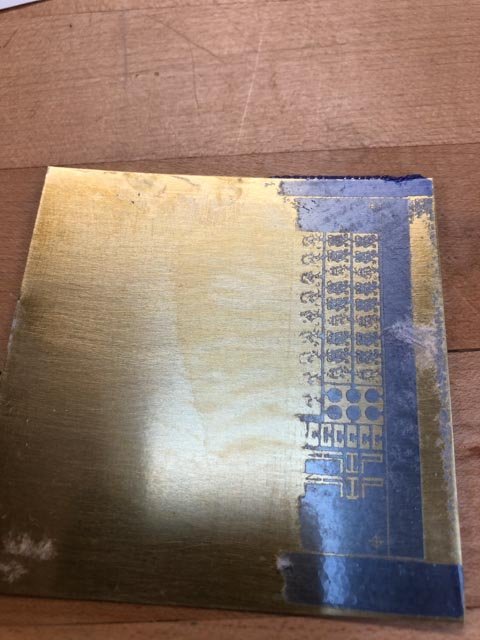
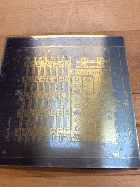
I might still be trying that. I learned more about photo etching today, getting as far as exposing and then developing the resist. I discovered (after talking to the great tech support at Micro Mark) that I had probably not cleaned the metal enough and/or run it through the laminator enough times. The resist had not stuck properly to the metal, and washed off completely in big areas.
So, the artwork is good, now I need to start again with the metal prep, exposure and development of the resist.
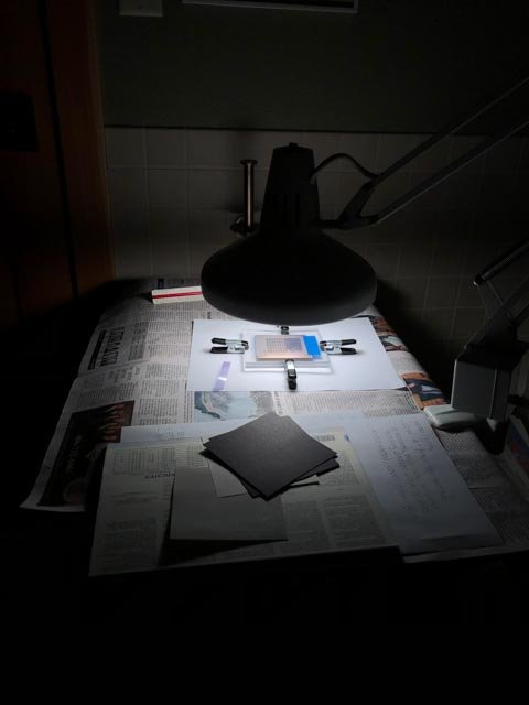
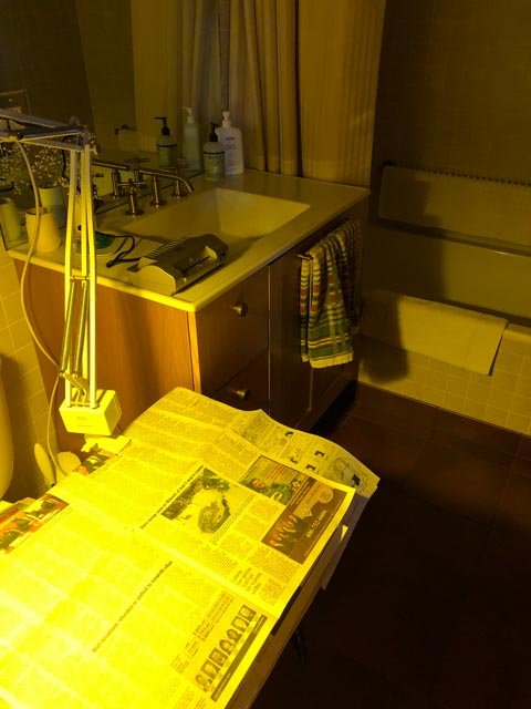
My wife is very patient about me taking over the guest bathroom for my developer studio...
Mark
-
Hi John,
It has taken a little mental adjustment to think about everything as a negative. It makes intellectual sense as I read it, but it doesn't stick intuitively that the black is what will be eaten away, especially since it is exposure to light that makes the mask.
I am intrigued by your circuit board experiments. How did it go?
I hope to see soon just how well this resolves. Interestingly, I had access to two printers for making the artwork; a relatively high end large format Canon printer that my wife used in her architecture practice, and our cheap home scanner/printer also by Canon. I was pretty amazed to see that the cheaper printer had finer resolution. It is a few years newer, but I didn't think the print resolution on inkjets had improved that much, and lower down the price range.
Hard to keep up with everything!
Mark
-
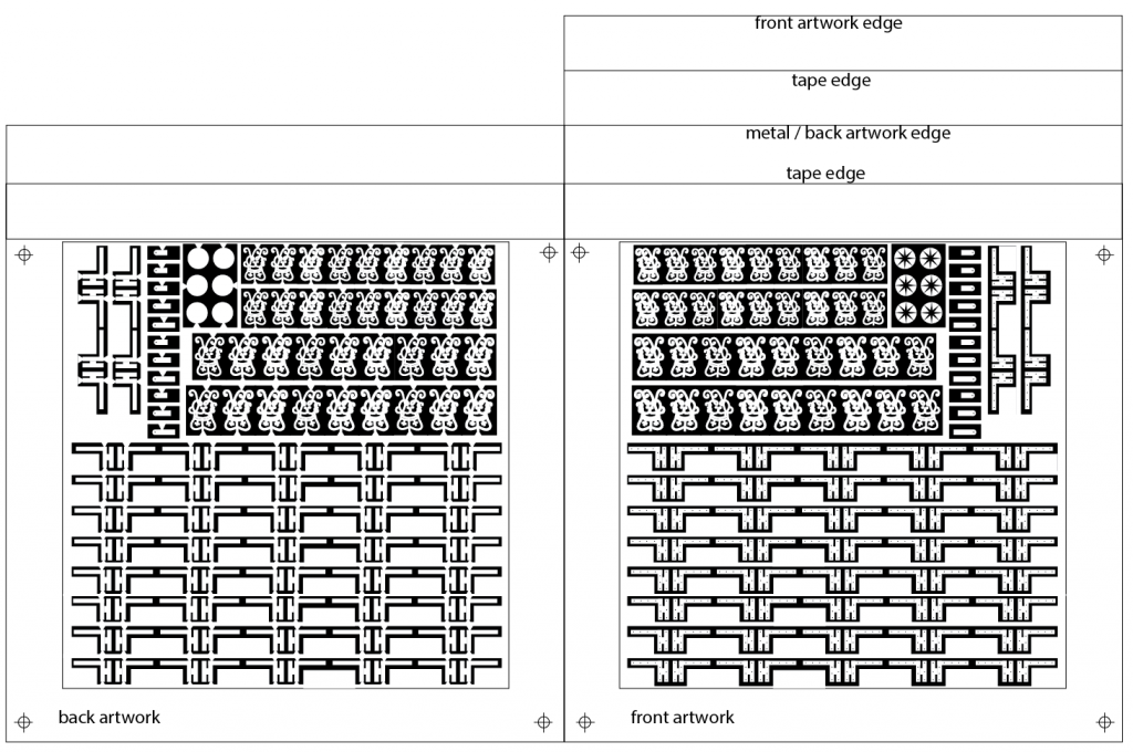
I learned a lot today about photo etching. First, the instructions and I came to a misunderstanding about the required length of the artwork film on front and back. They have to be taped together back to back while registering exactly. One side has to be longer so the other side can be taped to it, to form a hinge at the top. The metal then slips in between. I did it wrong, leaving too short a distance at the hinge to allow the artwork to slip down to be centered on the metal. So as long as I had to do the film again, I reworked the art so that I could get all of the hinges on. I also placed registration marks at the corners to help with aligning these to each other.
I also talked to tech support at Micro Mark. They were very helpful. They said that the exposure to a 60 watt bulb will do the job well. 100 watts tends to deform the plexiglass that the metal and artwork is temporarily sandwiched within, and fluorescent takes all day. 60 watts takes about 10 minutes per side. Time does not seem to be critical; the film will turn a darker blue when properly exposed, and there is no danger of too much exposure. Basically, the resist under the exposed areas (white) is being hardened by the UV light, so the unexposed areas (black) can be washed away to reveal the metal for etching. It apparently cannot be over-hardened with too much exposure.
Also, the ink side of the art work is placed directly against the resist film on the metal, which is why the artwork has to be reversed to read properly. So there is only the thickness of the ink to cast any shadows when being exposed, which appears to be negligible.
I had hoped to be further along today, but there was no rush because the sun never showed up here...
Mark
-
-
Beautiful work, Ed. It is always hard to imagine, when looking at a finished model, just how much time and thinking went into it. Your posts tell that story exceptionally well.
Mark
- Piet, michael mott, BETAQDAVE and 1 other
-
 4
4
-
-
John, I once lived in Denver, Colorado, which also had something like 300 days of sunshine a year. I appreciate what you have got in Brisbane! I should have done these guns two years ago before I moved. The weather report for here tomorrow no longer shows sunshine, which was going to be the only sunshine for the next 15 days. Druxey, I am going to call Micro Mark tomorrow and see if they can shed any light (so to say) on how I can do this with a lamp. Moving the lamp around is an interesting idea.
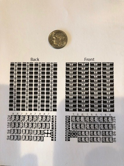
As usual, nothing quite goes as one expects. I printed out the artwork on the film and got satisfyingly high resolution, higher than the printer does on regular paper. However, I did not read the fine print in the instructions that the maximum recommended size is 3" by 3" for the metal, not the artwork; the artwork needs to have a margin of ½" within the metal all around. So my artwork was too big. A few failed attempts later, I finally got the film printed to the correct size. Used up the entire first sheet of film getting it right. And I don't have enough door hinges at this point. So there will be a round 2...
Best wishes,
Mark
- paulsutcliffe, druxey, GrantGoodale and 2 others
-
5
-
-
-
Hi druxey,
Quite true. They call my area the "banana belt" of Montana, ignoring the grey in the winter.
I just heard that I can drive to the top of a ski resort near here, where the lodge is at the top of the mountain. It often has sunshine when the rest of the valley is socked in due to a lake effect. That might be a way if the weather here does not cooperate. But then I will have to ski first!
By the way, do you think the Micro Mark instructions would be correct in saying that I can pull the photo resist material out of the black bag while using a yellow bug bulb, to avoid exposure to UV until everything is ready? I used to use a red light for old time photographic development, but this appears to be a different kind of exposure to a different aspect of the light. Wish I had paid more attention in those physics classes...
Mark
-
Thanks, Mark, I am happy to share what I learn, including mistakes and missteps.
Druxey, your comment about parallel light rays makes sense, particularly with the fine detail I am hoping to make.
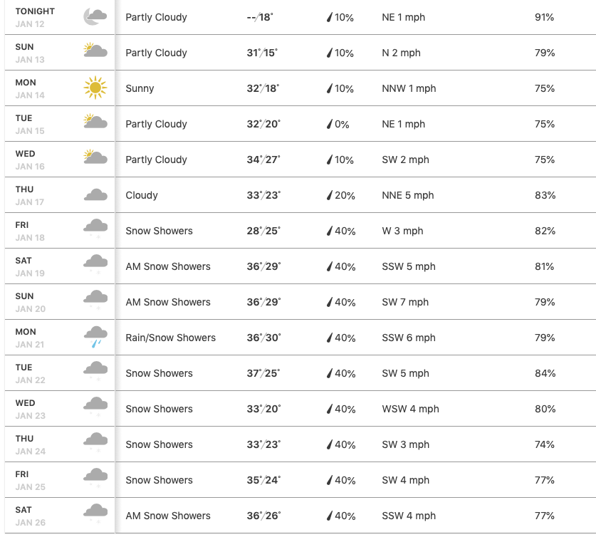
I have a potential window for the sun on Monday, the only day for the next 15 days (see the weather forecast below; it reminds me of when I lived in London in the mid 70s to mid 80s). I will see if I can get everything ready by then. If not, or if the weather projection is wrong about Monday, then I am looking at a long delay...
Or maybe I can send my metal blank to one of you who sees the sunshine more often! It will only take 15 seconds of exposure on each side.😊
No, that won't work because it needs to be developed very soon afterwards...
Best wishes,
Mark
-
Hi druxey,
The exposure part has me nervous. The instructions from Micro Mark say it can be exposed either by sunlight (noon, on a bright, cloudless day for 15 seconds each side), or a 60 watt incandescent bulb for 10 minutes each side, with the bulb 4" from the surface. However, earlier in the paragraph it says a 100 watt bulb.
My part of the country hasn't seen a bright, cloudless day in some time (yesterday was completely fogged in). So I was reconciled to using the light bulb. But 100 watt or 60 watt? I think I will call Micro Mark on Monday to get further guidance. What happens when we can't buy incandescent bulbs for love or money? Does an LED bulb give off UV the same as an equivalent incandescent bulb?
The eighteenth century model builders didn't have to worry about things like this!
Mark
- daHeld73, mtaylor and paulsutcliffe
-
3
-
Alan, too right about remembering to come back! I put off rebuilding the cannon for several years (admittedly, retiring and moving slowed down my ship production time).
At the risk of making too many boring postings, I thought others might find interesting my first explorations of photo etching as I proceed. I am using the Micro-Mark Pro-etch system from their catalog. The following is what I understand will happen:
The system will chemically etch metal wherever it is not protected by a photoresist mask. The mask has to be applied to both sides of the metal, otherwise it would just eat through the metal from the back irrespective of what mask was placed on the front.
Where the masks are the same on both sides, the metal will be etched all the way through. Where the masks are different, the etch will only go halfway through, leaving a depression on one side.
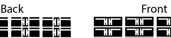
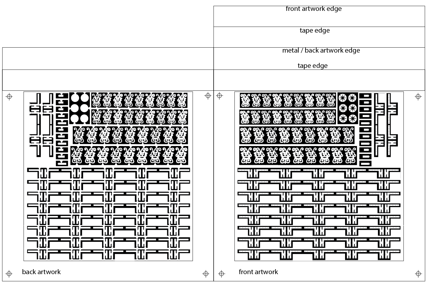
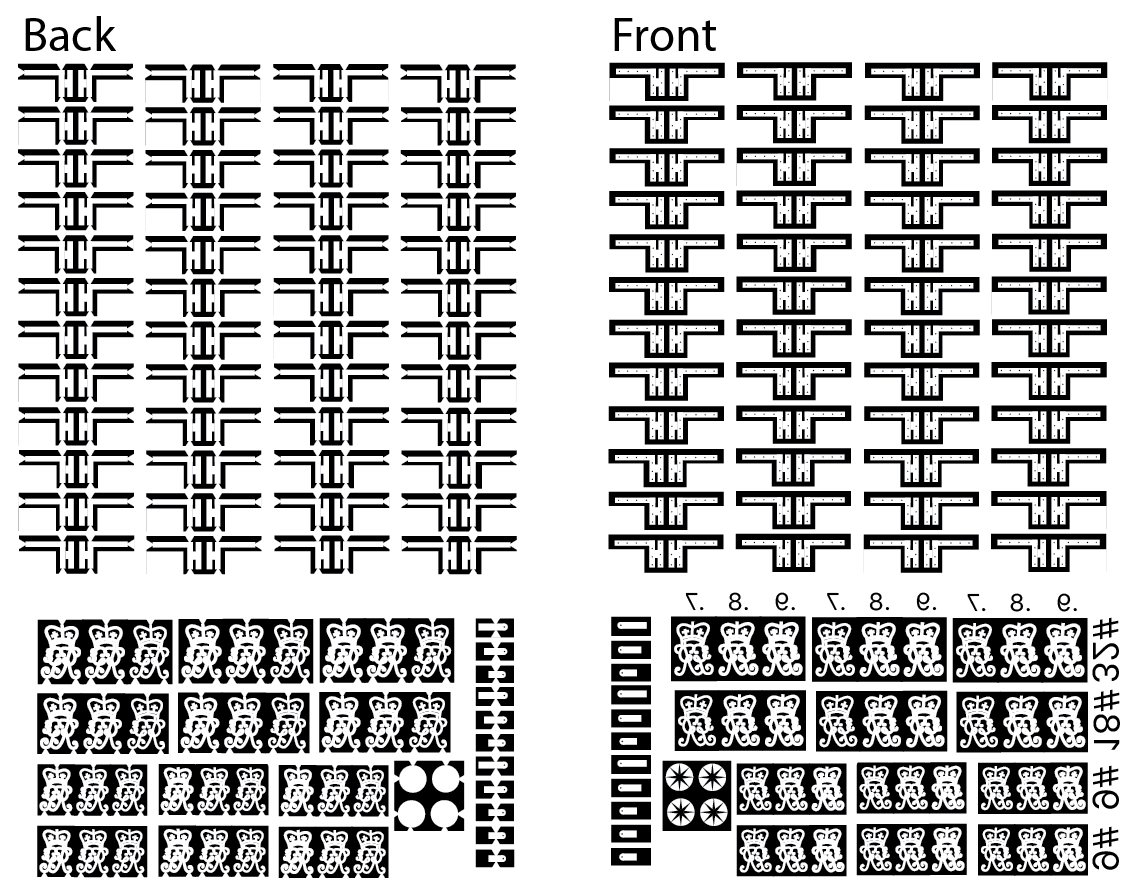
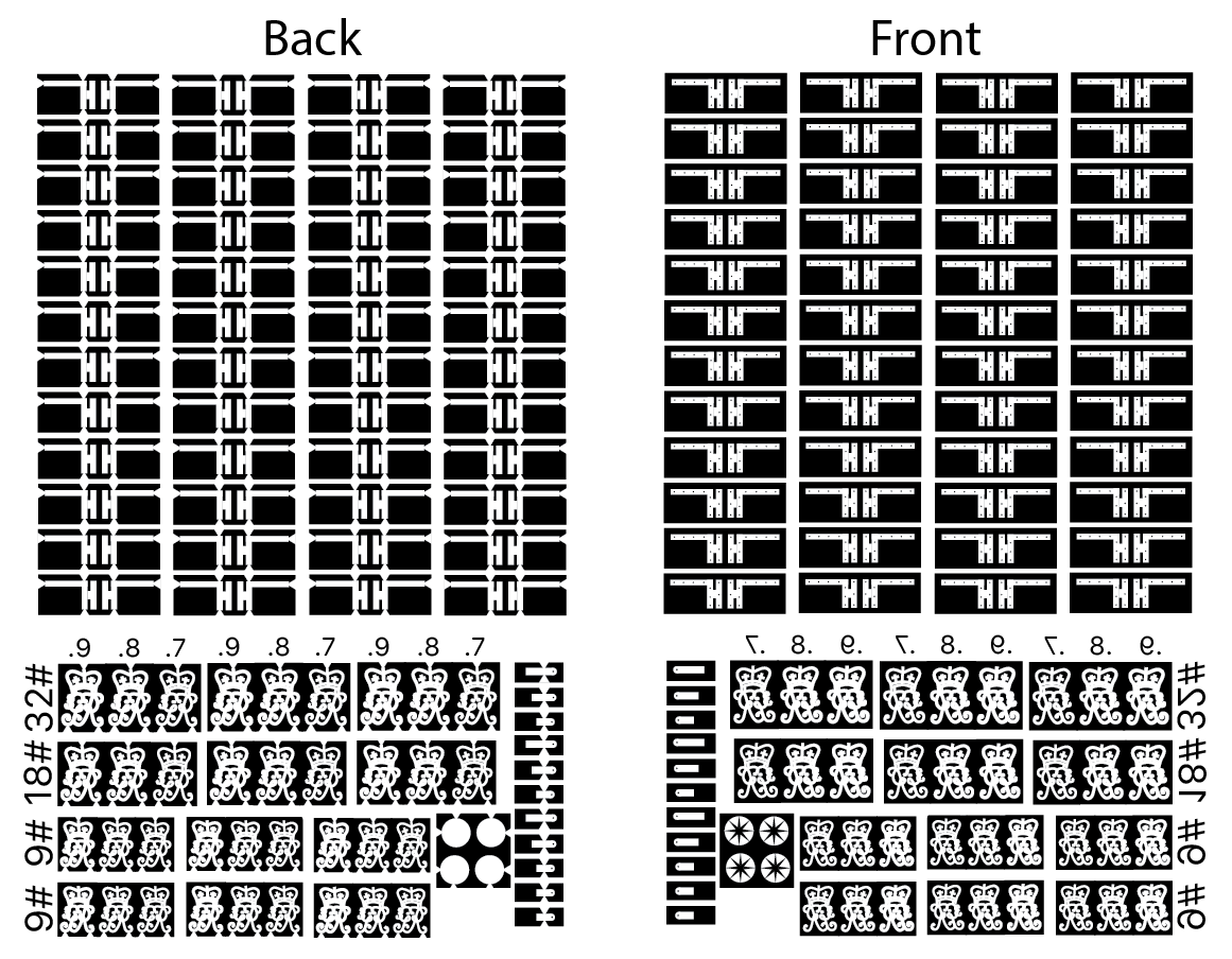
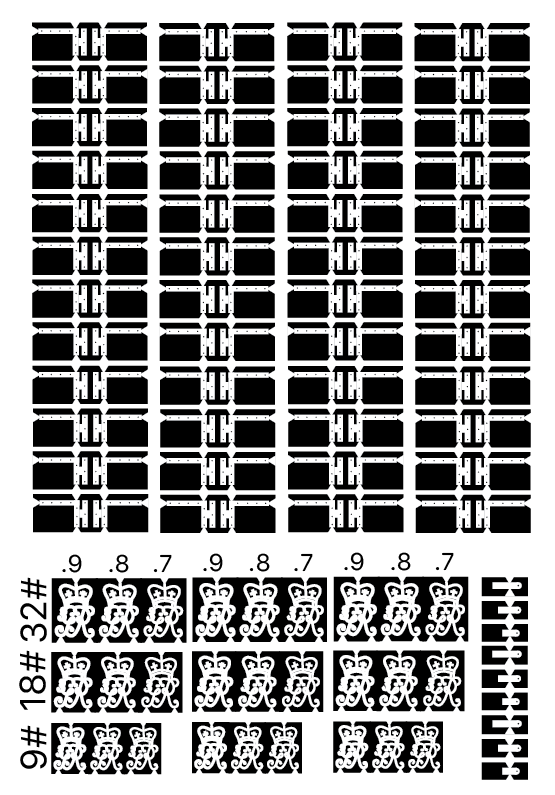
To create the photoresist mask, artwork is created for both sides of the metal, each the mirror image of the other so the two sides line up precisely. This involves making the artwork for one side, then creating a mirror image for the other. The artwork will then be used as a mask to expose the photoresist on the metal to UV light, white areas protecting the photoresist material and therefore protecting the metal underneath from etching, and the black areas eating away the resist and therefore allowing the metal in these locations to be etched.
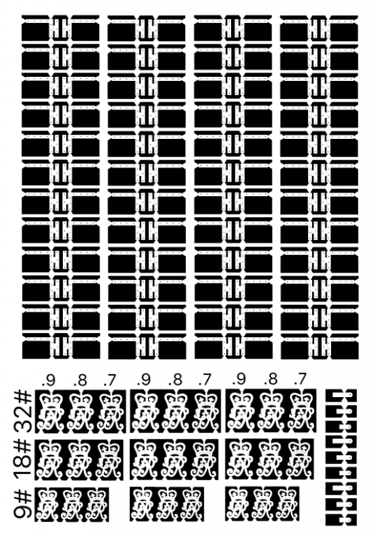
Using Adobe Illustrator, I drew the artwork, then created a mirror image for the mask on the other side. Looking at the door hinges, I created black dots for bolt locations on the front side, and removed these on the back side so they will not etch all the way through. Similarly, I added white triangles on the back side to hold the pieces in place when the etch is completed; these thinner parts will be cut through just like cutting parts from sprues in plastic models.
I need to rig a dark interior room with a yellow light so I can work with the photo resist and not expose it to UV light until everything is ready to go. The exposure to develop the resist is done with a 60 watt incandescent bulb (fortunately, I still have one in my old drafting light). Many unknowns still to go!
Mark
-
Hi Doris,
I have long admired those dolphin supports in contemporary models, and have vaguely thought about making something like that for my own project. I look forward to seeing how you make these!
Mark
- popeye the sailor, EJ_L, DORIS and 1 other
-
4
-
-
Hi Bob, thank you very much for your comments. As you can see, I am very often learning as I go along. And many of the great builders on this website have taught me more than I would ever would have discovered for myself. Learning from a lot of mistakes has also helped! Sometimes when the mistakes are really bad, I put those aside for a while and go onto something else to get my confidence back, and then revisit the mistake to try another approach. I tried making the cannon several years ago, and was quite discouraged by the outcome. A few years later, I have renewed energy to do it better.
Mark
-
-
Hi Greg,
Yes, that is my plan. I have made several of each in case I screw up attaching to the master cannons, and also to see what happens with different thicknesses of lines. I am not yet sure just how much the Micro Mark etching kit will resolve down to these fine lines.
And as long as I have to use up a 3X3 sheet, I might as well fill it up!
Mark
- paulsutcliffe, druxey and daHeld73
-
3
-
Hi everyone,
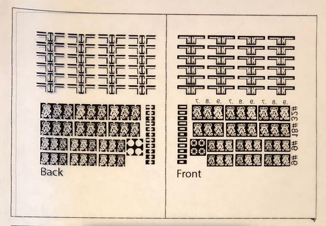
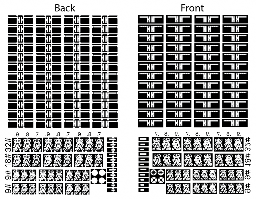
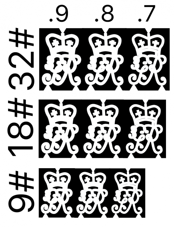
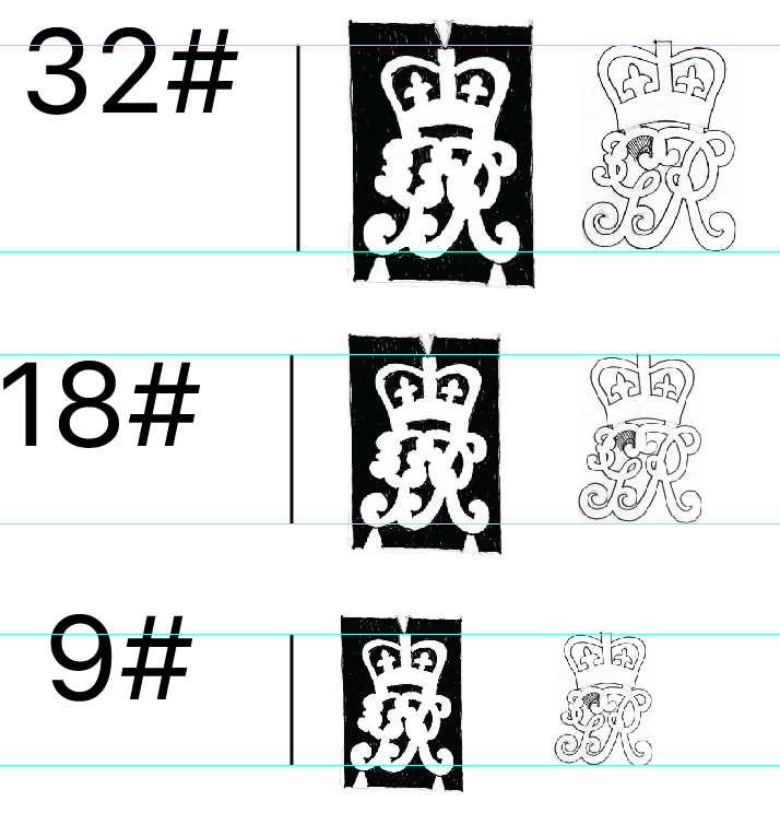
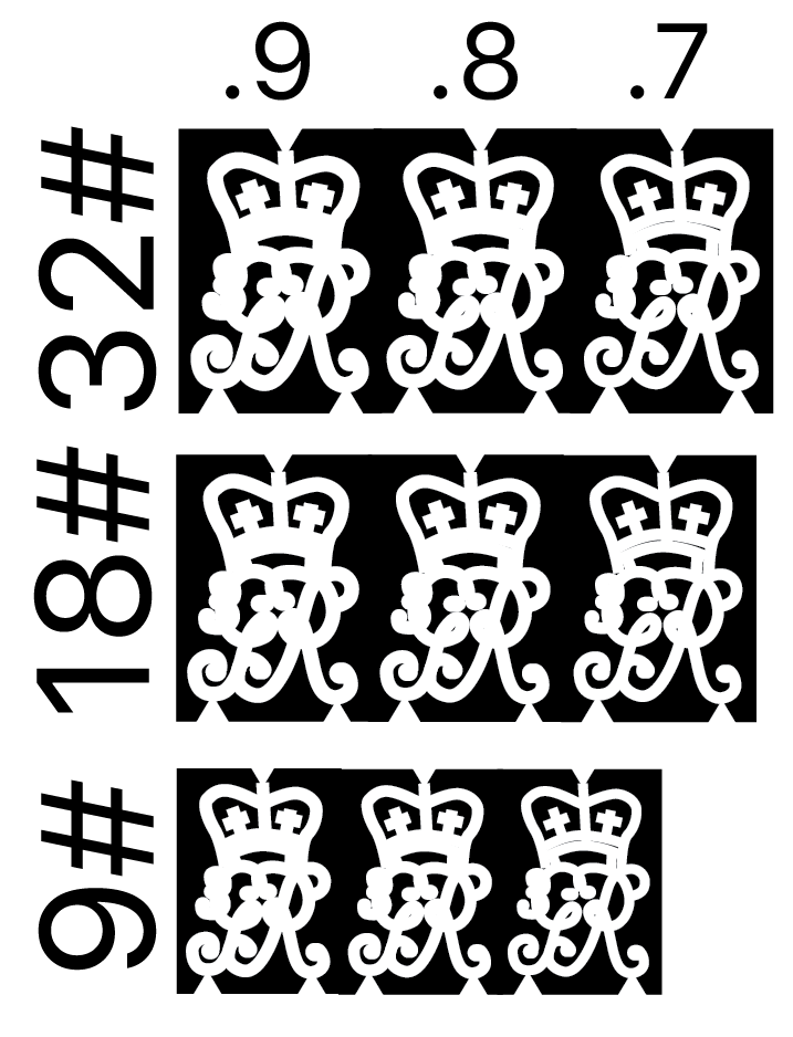
I spent a little more time in Adobe Illustrator, trying to get cleaner drawings of the king's cyphers for photo etching. Once I got the hang of the pen tool, I was able to draw the forms rather than filling in the backgrounds (my previous attempt). And this allowed me to vary the thickness of the lines. Since I don't know how well the photo etch will deal with fine detail, I will try a couple with different thicknesses of line, hoping some good ones come out of the mix.
Thinking about other metal objects that would be 5/16" thick real size to fill up the sheet, I have drawn up the door hinges for all of the partitions. I also drew some vent fields for the cannon.
Can anyone think of other metal objects this thin, while I am at it? I thought about the compass. The etching process is supposed to etch from both sides, which means that there can be recessed parts not cut through all the way depending on how the art is arranged. Maybe cut the compass rose into one side? Not sure how I would color that to pick out the raised parts later.
Maybe the pump rhodings?
Mark
-
Thank you, Jorge, druxey and Doris for your kind comments. And Doris, again I am amazed what you can do with clay, now that I have tried and failed to create details like you have done for your projects.
Drawing the cyphers for photo-etching is proving to be challenging, given their size. Working in Adobe Illustrator, I discovered that they need to be fattened up, or the fine lines just disappear when shrunk down to scale. I don't know yet how fine the Micro Mark photo-etch paper will resolve either, so a little experimentation in in order now.
Mark
-
Hi everyone,
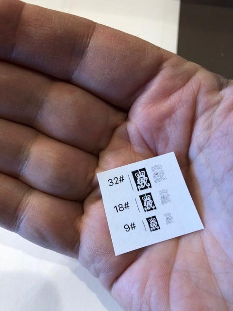
Cannon masters finally done. Here are the four guns of the Bellona: 32# on the gundeck, 18# on the upper deck, 9# long on the forecastle, and 9# short on the quarterdeck.
Now on to the king's cypher. I have even additional appreciation for Doris's amazing work with clay. I was not able to get anywhere close to her skill trying to make the cyphers that way. So I will try my Micro Mark photo etching kit and see how well I can do with that. The chemicals were way out of date, so waiting for renewed stock in the mail.
Mark

-
-
Hi Michael,
Just catching up. Everything is looking wonderful, and I am particularly impressed with your machining and metal working. It all seems impossibly difficult until you demonstrate it, which makes it even more magical!
Mark
-
Those shipworkers can sometimes get a little frisky!
Mark
- DORIS, popeye the sailor, EJ_L and 3 others
-
6
HMS Winchelsea 1764 by Stuntflyer (Mike) - FINISHED - 1/4" scale
in Member Build logs for the HMS Winchelsea
Posted
Hi MIke,
Beautiful work!
I somehow got the idea in my head that the red paint at the gunports would extend out along the revealed edges of the planking, to meet the face of the planking at the outer edge, not the inner edge. Do you have another understanding, or are you planning to paint those edges later?
I have been fretting over how to do this myself, assuming I did not misunderstand this detail!
Best wishes,
Mark